HK Audio ELEMENTS E 115 Sub D User manual

ELEMENTS
E 115 Sub D
MANUAL 1.1
• English • Français• Deutsch • Italiano • Español
Leave enough space for proper ventilation!
ELEMENTS
E 115 SubD
MADE IN GERMANY
Preset
Thru
In
1x E 835
Power
Auto Sleep
2x E 835
3x E 835
Remote
1
2
3
4
On Off
Ethernet
0dB
Input
Cardioid Out
Thru Gain
Data
Serial No.
Mains Input
100-240 V~
50-60 Hz
1.9 A @ 1/8
output power
Caution: Risk of electric shock! Do not open!
Refer servicing to qualified service personnel.
Attention: Risque de choc élèctrique –
ne pas ouvrir!
HK Audio is a brand of Stamer Musikanlagen GmbH
.BHEFCVSHFS4USŦ4U8FOEFMŦ(FSNBOZ
Power
Mid/High Out
E 835
Lock
1+/1–
+6 dB
Small Venue
Front
Cardioid
E 115 Sub D
L SUB 1500 A
Set Gain Bass
to +6 dB
Leave 1 meter
of space in each
direction!
Cardioid Setup
Important Safety Instructions!
Read before connecting!
This product has been built by the manufacturer in accordance with
IEC 62368-1 and left the factory in safe working order. To maintain
this condition and ensure non-risk operation, the user must follow the
advice and warning comments found in the operating instructions. If
this product shall be used in vehicles, ships or aircraft or at altitudes
exceeding 2000 m above sea level, take care of the relevant safety
regulations which may exceed the IEC 62368-1 requirements.
WARNING: To prevent the risk of fire and shock hazard, do not
expose this appliance to moisture or rain. Do not open case – no user
serviceable parts inside. Refer service to qualified service personnel.
This symbol, wherever it appears, alerts you to the presence
of uninsulated dangerous voltage inside the enclosure – voltage that
may be sufficient to constitute a risk of shock.
This symbol, wherever it appears, alerts you to the presence
of externally accessible hazardous voltage. External wiring connected
to any terminal marked with this symbol must be a “ready made
cable” complying with the manufacturers recommendations, or must
be a wiring installed by instructed persons only.
This symbol, wherever it appears, alerts you to important
operating and maintenance instructions in the accompanying
literature. Read the manual.
This symbol, wherever it appears, tells you: Take care! Hot
surface! To prevent burns you must not touch.
All electrical and electronic products including batteries
should be disposed of separately from the municipal waste stream via
designated collection facilities appointed by the government or the
local authorities.
Read these instructions. Keep these instructions. Follow all
warnings and instructions marked on the product and in this manual.
• Do not use this product near water. Do not place the product near
water, baths, wash basins, kitchen sinks, wet areas, swimming pools
or damp rooms.
• Do not place objects containing liquid on the product – vases,
glasses, bottles etc.
• Clean only with dry cloth.
• Do not remove any covers or sections of the housing.
• The set operating voltage of the product must match the local mains
supply voltage. If you are not sure of the type of power available
consult your dealer or local power company.
• Before connecting the device, please ensure that the mains supply
you are using is equipped with adequate protection against short
circuiting and grounding faults when the device is plugged in.
• To reduce the risk of electrical shock, the grounding of this product
must be maintained. Use only the power supply cord provided with
this product, and maintain the function of the center (grounding)
pin of the mains connection at any time. Make sure the mains outlet
used provides a proper protective ground connection.
• Do not defeat the safety purpose of the polarized or grounding-type
plug. A polarized plug has two blades with one wider than the other.
A grounding type plug has two blades and a third grounding prong.
The wide blade or the third prong are provided for your safety. If the
provided plug does not fit into your outlet, consult an electrician for
replacement of the obsolete outlet.
• Protect the power cord from being walked on or pinched particularly
at plugs, convenience receptacles, and the point where they exit
from the device! Power supply cords should always be handled
carefully. Periodically check cords for cuts or sign of stress,
especially at the plug and the point where the cord exits the device.
• Never use a damaged power cord.
• Unplug this product during lightning storms or when unused for long
periods of time.
• This product can be fully disconnected from mains only by pulling
the mains plug at the unit or the wall socket. The product must be
placed in such a way at any time, that disconnecting from mains is
easily possible.
• Fuses are to be replaced exclusively by qualified personnel, and then
only with fuses of the proper type and rating.
• Refer all servicing to qualified service personnel. Servicing is
required when the unit has been damaged in any way, such as:
- When the power cord or plug is damaged or frayed.
- If liquid has been spilled or objects have fallen into the product.
- If the product has been exposed to rain or moisture.
- If the product does not operate normally when the operating
instructions are followed.
- If the product has been dropped or the cabinet has been damaged.
• Do not connect external speakers to this product with an impedance
lower than the rated impedance given on the product or in this
manual. Use only cables with sufficient cross section according to
the local safety regulations.
• Keep away from direct sunlight.
• Do not install near heat sources such as radiators, heat registers,
stoves or other devices that produce heat.
• This apparatus is for moderate climates areas use, not suitable for
use in tropical climates countries.
• Do not block any ventilation openings. Install in accordance with
manufacturer’s instructions. This product must not be placed in
a built-in installation such as a rack unless proper ventilation is
provided.
• Always allow a cold device to warm up to ambient temperature,
when being moved into a room. Condensation can form inside it and
damage the product, when being used without warming up.
• Do not place naked flame sources, such as lighted candles on the
product.
• The device must be positioned at least 20 cm/8" away from walls.
• Use only with the cart, stand, tripod, bracket or table specified by
the manufacturer or sold with the product. When a cart is used, use
caution when moving the cart/product combination to avoid injury
from tip-over.
• Use only accessories recommended by the manufacturer, this applies
for all kind of accessories, for example protective covers, transport
bags, stands, wall or ceiling mounting equipment. In case of
attaching any kind of accessories to the product, always follow the
instructions for use, provided by the manufacturer. Never use fixing
points on the product other than specified by the manufacturer.
• This appliance is NOT suitable to be used by any person or persons
(including children) with limited physical, sensorical or mental
ability, or by persons with insufficient experience and/or knowledge
to operate such an appliance. Children under 4 years of age must be
kept away from this appliance at all times.
• Never push objects of any kind into this product through cabinet
slots as they may touch dangerous voltage points or short out parts
that could result in risk of fire or electric shock.
• This product is capable of delivering sound pressure levels in excess
of 90 dB, which may cause permanent hearing damage! Exposure
to extremely high noise levels may cause a permanent hearing loss.
Wear hearing protection if continously exposed to such high levels.
• The manufacturer only guarantees the safety, reliability and
efficiency of this product if:
- Assembly, extension, re-adjustment, modifications or repairs are
carried out by the manufacturer or by persons authorized to do so.
- The electrical installation of the relevant area complies with the
requirements of IEC (ANSI) specifications.
- The unit is used in accordance with the operating instructions.
• This product is optimized for use with music and speech signals.
Using this product with sine wave, square wave or other kind of
measuring signals at higher level may lead to severe damage of the
product.
General Notes on Safety for Loudspeaker
Systems
Mounting systems may only be used for those loudspeaker
systems authorized by the manufacturer and only with the mounting
accessories specified by the manufacturer in the installation
instructions. Read and heed the manufacturer’s installation
instructions. The indicated load-bearing capacity cannot be
guaranteed and the manufacturer will not be liable for damages in the
event of improper installation or the use of unauthorized mounting
accessories.
The system’s load-bearing capacity cannot be guaranteed and
the manufacturer will not be liable for damages in the event that
loudspeakers, mounting accessories, and connecting and attaching
components are modified in any way.
Components affecting safety may only be repaired by the
manufacturer or authorized agents, otherwise the operating permit
will be voided.
Installation may be performed qualified personnel only,
and then only at pick-points with sufficient load-carrying capacity
and in compliance with local building regulations. Use only the
mounting hardware specified by the manufacturer in the installation
instructions (screws, anchors, etc.). Take all the precautions necessary
to ensure bolted connections and other threaded locking devices will
not loosen.
Fixed and portable installations (in this case, speakers
and mounting accessories) must be secured by two independent
safeties to prevent them from falling. Safeties must be able to
catch accessories or parts that are loose or may become loose.
Ensure compliance with the given national regulations when using
connecting, attaching, and rigging devices. Factor potential dynamic
forces (jerk) into the equation when determining the proper size and
load-bearing capacity of safeties.
Be sure to observe speaker stands’ maximum load-bearing
capacity. Note that for reasons of design and construction, most
speaker stands are approved to bear centric loads only; that is, the
speakers’ mass has to be precisely centered and balanced. Ensure
speaker stands are set up stably and securely. Take appropriate added
measures to secure speaker stands, for example when:
- the floor or ground surface does not provide a stable, secure base.
- they are extended to heights that impede stability.
- high wind pressure may be expected.
- there is the risk that they may be knocked over by people.
Special measures may become necessary as precautions against
unsafe audience behavior. Do not set up speaker stands in evacuation
routes and emergency exits. Ensure corridors are wide enough and put
proper barriers and markings in place when setting speaker stands up
in passageways. Mounting and dismounting are especially hazardous
tasks. Use aids suitable for this purpose. Observe the given national
regulations when doing so.
Wear proper protection (in particular, a helmet,
gloves, and safety shoes) and use only suitable means of ascent
(ladders, scaffolds, etc.) during installation. Compliance with this
requirement is the sole responsibility of the company performing the
installation.
WARNING! After installation, inspect the system comprised
of the mounting fixtures and loudspeakers to ensure it is properly
secured.
The operator of loudspeaker systems (fixed or portable) must
regularly inspect or task a third party to regularly inspect all system
components in accordance with the given country’s regulations and
have possible defects repaired immediately.
We also strongly recommend maintaining a logbook or the like to
document all inspections.
Also be sure to provide sufficient safety margins for the rigging points
used for flown systems. Observe the given national regulations when
doing so.
Professional loudspeaker systems can produce harmful
volume levels. Even prolonged exposure to seemingly harmless levels
(starting at about 95 dBA SPL) can cause permanent hearing damage!
Therefore we recommend that everyone who is exposed to high
volume levels produced by loudspeaker systems wears professional
hearing protection (earplugs or earmuffs).
Manufacturer: Stamer Musikanlagen GmbH, Magdeburger Str. 8,
66606 St. Wendel, Germany
Version 2.8 08/2019

ELEMENTS E 115 Sub D 1.1
3
Welcome to the HK Audio family!
Thank you for choosing a brand-name product made by our company. Rest
assured, we engineered and built it with the greatest care so it will serve
you well for many tomorrows to come.
Even if your experience with sound systems runs deep, some things
about this product are sure to be new to you. This is why we ask that you do
not set this manual aside without reading it first. Be sure to keep it in a
safe place for later reference.
Here’s wishing you the best sound at every occasion!
Your HK Audio team
Warranty
Use the convenient online registration option at www.hkaudio.com.
http://warranty.hkaudio.com
The registration is only valid if the device is registered within 30 days of
the date of purchase.
HK AUDIO
Technischer Service
Postfach 1509
66595 St. Wendel, Germany
Fax: +49 6851 905 100
Powerful electromagnetic interference and electrostatic
discharges may impair this unit's operation. In the event of such
interference, switch the device o and back on again. If this fails to
restore the normal mode of operation, please move the unit away from
the source of interference and try again.
1 General Information
Unpacking and Inventorying
When you first unpack your ELEMENTS E 115 Sub D speaker cabinet, take
a quick inventory to make sure it comes complete with the manual and
Powercon mains cable.
The System's Components
Heads up: Please be advised that the E 115 Sub D subwoofer may only be
operated in combination with passive HK Audio ELEMENTS components.
Heads up: Connecting any component other than ELEMENTS mid/high
units to this Speakon output may damage it and destroy the subwoofer’s
electronics.
Powering Up
Make certain that the E 115 Sub D is switched o when you set up the
system, otherwise you risk damaging it! Always set up the entire system
and connect all cables first, and then switch on the subwoofer last. When
tearing the system down, always switch o the ELEMENTS subwoofer first.
• English • Français• Deutsch • Italiano • Español
ELEMENTS E 115 Sub D

ELEMENTS E 115 Sub D 1.1
4
Leave enough space for proper ventilation!
ELEMENTS
E 115 SubD
MADE IN GERMANY
Preset
Thru
In
1x E 835
Power
Auto Sleep
2x E 835
3x E 835
Remote
1
2
3
4
On Off
Ethernet
0dB
Input
Cardioid Out
Thru
Data
Serial No.
Mains Input
100-240 V~
50-60 Hz
1.9 A @ 1/8
output power
Caution: Risk of electric shock! Do not open!
Refer servicing to qualified service personnel.
Attention: Risque de choc élèctrique –
ne pas ouvrir!
HK Audio is a brand of Stamer Musikanlagen GmbH
.BHEFCVSHFS4USŦ4U8FOEFMŦ(FSNBOZ
Power
Mid/High Out
E 835
Lock
1+/1–
+6 dB
Small Venue
Front
Cardioid
E 115 Sub D
L SUB 1500 A
Set Gain Bass
to +6 dB
Leave 1 meter
of space in each
direction!
Cardioid Setup
Gain Sub
1
6
5
4
10
11
12
13
14
7
9
2
8
3
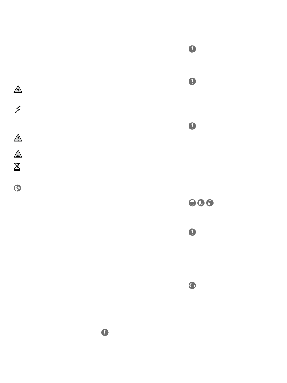
2 Connectors and Controls
●
1Input
This XLR/ 1/4" (6.35 mm) combo jack provides a balanced input for analog
signals.
●
2Thru
Use this parallel, balanced XLR output to send the signal routed into the
Input through to other components. This output remains active even when
the electronic components are deactivated.
●
3Gain Sub
Use this knob to adjust the input gain for the incoming signal.
Heads up: This knob adjusts the volume of the E 115 Sub D. It does not
address or aect the connected mid/high units. We recommend starting
with it set to 0 dB at the center or 12 o’clock position.
●
4Input/Limiter LED
This LED lights up green to indicate incoming signals and red to indicate
signal peaks. The LED briefly flashes red to tell you the Limiter is
responding to signal peaks. If it stays red, turn down the Gain knob.
●
5Cardioid Out
Connect a matching HK Audio LINEAR SUB 1500 A subwoofer to this output
when configuring cardioid setups. See section 5.2 for more on this.
●
6Ethernet In /Thru
Use the two Ethercon ports to integrate the speaker into a network. They
accept RJ45 and Ethercon (NE8 MX, NE8 MX6, NE8 MC) plugs. Use the
Ethernet Thru port to forward the network signal.
Always use S/STP or S/FTP cables to shield against electromagnetic
interference. We recommend CAT6 cables. A separate manual explains the
finer points of network integration, remote control functions and audio
streaming.
You will find it on the ELEMENTS download page at www.hkaudio.com. For
a brief description of the DSP functions, see section ●
8Preset.
●
7Data
This LED lights up orange when data flows through the network connector.
●
8Preset
Use the Preset selection button to call up factory presets or a user preset
you can configure via the remote DSP CONTROL software. Tap the select
button once to scroll through Presets 1 through 4.
A separate manual explains how to program the four remote user presets.
You will find it on the ELEMENTS download page at www.hkaudio.com.
Heads up: Selecting the proper preset tunes the subwoofer’s frequency
response to match the frequency response of the connected mid/high
units. It is essential that you to do this manually because the power amp
cannot automatically detect the number of connected mid/high units.
Heads up: The numbers indicated for the Filter button always apply to
the E 835 model of mid/high unit. Be sure to multiply that number by
two when using the E 435 model.

ELEMENTS E 115 Sub D 1.1
5
Preset 1: 1x E 835 (2x E 435)
Preset 2: 2x E 835 (4x E 435)
Preset 3: 3x E 835 (6x E 435)
Heads up: You can combine the two models in a mixed configuration, for
example, two E 835s and two E 435s. It this case, you would select Preset
3. You can even connect an odd number of E 435s, say, two E 835s and
one E 435s or three E 435s. In these cases, select the next lower preset
number and, if necessary, adjust the high frequencies using the mixer’s
EQ or the frequency response using HK Audio DSP CONTROL software.
E 835 E 835 E 435
E 435 E 435 E 435
Preset
2
E 835 E 835 E 835
Preset
3
E 835 E 835
Preset
2
Preset
1
E 435 E 435
Preset
1
E 835
Preset
1
1x
E 835
2x
E 435
=
Preset 4: Remote
This setting loads a user preset previously saved via the DSP CONTROL
application. The subwoofer does not need to be connected to the remote
software to do this.
You can save the following DSP functions via the remote DSP CONTROL
software as user presets – the fully parametric ten-band EQ with variable
filter characteristics for each frequency band, a high-pass and a low-pass
filter with variable filter characteristics, and limiter, delay, level and mute.
This screenshot shows the remote DSP CONTROL software. You can get this free application from the
ELEMENTS product download page at www.hkaudio.com.
●
9Small Venue
We tuned your ELEMENTS system’s frequency response for larger rooms,
which require speakers to throw sound over greater distances. When
setting the system up in smaller rooms, activate the Small Venue EQ with
this switch so the red LED lights up. This re-voices the system for it to
sound balanced and remarkably transparent even at very short range.
●
10 Mid/High Out
Connect ELEMENTS mid/high units to this Speakon output via the EF 45
base (available as an accessory) or to forward their signal to an ELEMENTS
Install Kit.
Use standard cables equipped with Speakon NL2 connectors to this end.
Plug in the Speakon cable and turn the connector clockwise to lock it in
place. Be sure to first turn the connector counterclockwise to unlock it
before unplugging it.
Heads up: Mid/High Out is wired in parallel to the E-Connect (15) signal
bus on top of the E 115 Sub D. Use this output only when the E-Connect
bus is not in use.
Heads up: Connecting any component other than ELEMENTS mid/high
units to this Speakon output may damage it and destroy the subwoofer’s
electronics.
●
11 Mains Input
Use the factory-included Powercon mains cord to connect this socket to a
power outlet. Insert the push-pull connector and turn it clockwise to make
sure the Powercon cord engages and locks. To unlock it, pull the Powercon
plug's locking mechanism towards the cable and turn it counterclockwise.
●
12 Power
This rocker switch turns the power on and o. Set it to Power to turn the
electronic components on and to O to disconnect them from the mains
power supply.
●
13 Power-LED
This LED lights up green when the electronic components are getting mains
power.
●
14 Auto Sleep
Use this recessed button to switch energy-saving Auto Sleep mode on and
o. Your speaker leaves the factory with the Auto Sleep button pressed to
enable this mode. This function puts the electronic components to sleep
when four and a half hours pass without the speaker registering an audio
signal, data sent to the Ethercon ports, or an adjustment of a button or
knob. The only way to wake it up is by switching the Power button o and
on again or patching an analog audio signal into the Input.
●
15 E-Connect
The dual-purpose ELEMENTS E-Connect output/coupler is located on the
top of the E 115 Sub D enclosure. Use it to connect E 835 and E 435 mid/
high units and the EP 1 and EP 2 speaker extension poles. The subwoofer
can drive up to three E 835 mid/high units or up to six E 435s. For more on
this, see section 3, Setting Up and Connecting the Column’s components.
Heads up: The E-Connect bus is wired in parallel to the Mid/High Output
on the rear panel (Speakon). Use it only when the Speakon Out port is not
in use.
• English • Français• Deutsch • Italiano • Español

ELEMENTS E 115 Sub D 1.1
6
3 Setting Up and Connecting the
Column's Components
3.1 E-Connect
E-Connect is a fast, reliable and cordless way of linking the ELEMENTS'
passive components. This dual-purpose coupler provides physical and
audio links that connect the E 835 mid/high-units, the EP 1 / EP 2 speaker
extension pole and the EF 45 base.
3.2 Connecting the Column's Components
Line up the two components so that the pole end faces the sleeve. Insert
the pole end all the way into sleeve until the detent button snaps into
place, making sure you have a solid connection.
Push!
To disconnect and separate the units, press and hold the button on the
E-Connector to release the detent and then pull the two components apart.
Pull!
Heads up: Always set the system up on flat, level and firm surfaces.
4 Setting Up
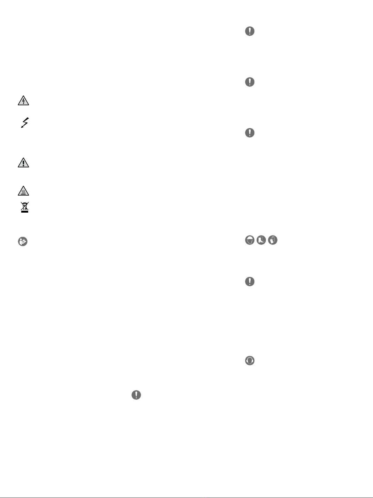
4.1 Vertical Alignment
What height is right?
Line array systems like ELEMENTS deliver a fairly narrow vertical output
pattern. This is why you want to aim the speakers so the center of the
column is roughly in line with the audience’s heads.
Two speaker extension poles of dierent lengths, the EP 1 and the EP 2, are
available to adjust the column’s height.
Equipped with the cordless E-Connect bus/coupler, they provide a fast, easy
way of setting up smaller configurations and connecting mid/high units.
Consult the technical specifications to learn the exact measurements of the
two speaker extension poles.
Heads up: Never connect two speaker extension poles to each other!
4.2 Horizontal Alignment
A mid/high column’s horizontal directivity is around 70°. Depending on
the application, you may want to turn the columns inwards towards the
audience area to direct the system's power where it is needed most.
70°
You'll get the best sound and coverage when all connected components
project at the same angle. The included locking wedges lets you lock down
the ELEMENTS mid/high-units so their aim remains true and they can't
drift to the left or right.
Push!
Insert the locking wedge into the slot until it clicks into place. Apply slight
pressure to the center panel to release and remove it.
ELEMENTS E 115 Sub D 1.1
7
4.3 Maximum Configuration
This is the largest system you can configure with the E 115 Sub D:
1x
E 835
E 835
E 115 Sub E
E 835 E 835
2x
E 435
=
5 Bass Extension and Cardioid Setups
with the HK Audio LINEAR SUB 1500 A
A perfect acoustical, mechanical and visual match, the powered HK Audio
LSUB 1500 A subwoofer is the ideal complement to the E 115 Sub D. Be sure
to set the LINEAR SUB 1500 A’s Phase switch to 0 degrees and the X-Over
Bass switch to 100 Hz before connecting this subwoofer. The position of
the Configuration switch is irrelevant in this case because it only aects the
level of the LINEAR SUB 1500 A’s Line Out Mid/High ports.
The E 115 Sub D oers two outputs that let you add on the LINEAR SUB
1500 A, either as a bass extension or to configure a cardioid setup:
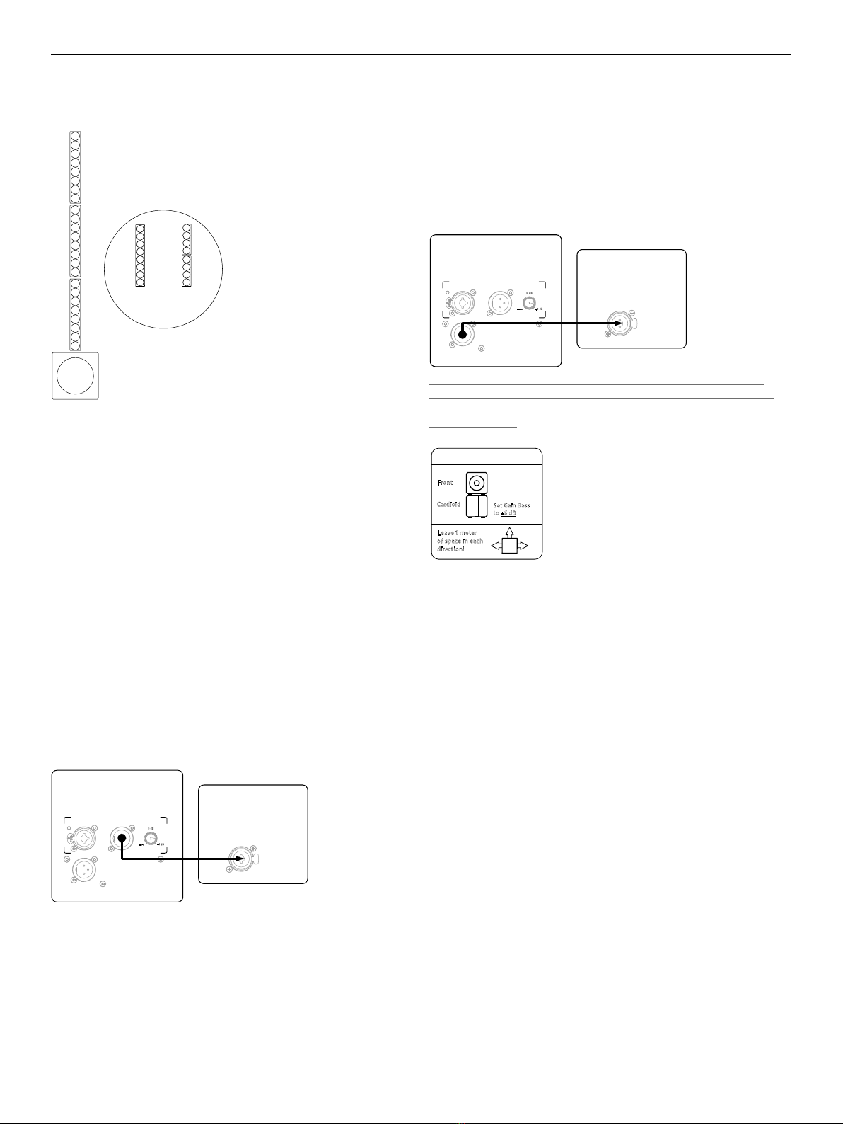
5.1 Operating the LINEAR SUB 1500 A as a Bass
Extension
Connect the LINEAR SUB 1500 A to the Thru ports on the E 115 SUB A for it
to receive the unprocessed signal routed into the E 115 Sub D’s input. Adjust
the level using the Gain Bass knob on the LINEAR SUB 1500 A. In this case,
you can place the LINEAR SUB 1500 A beneath or beside the E 115 Sub D.
ELEMENTS
E 115 SubD LINEAR SUB
1500 A
0dB
Input
Input
Cardioid Out
Thru
+6 dB
Gain Sub
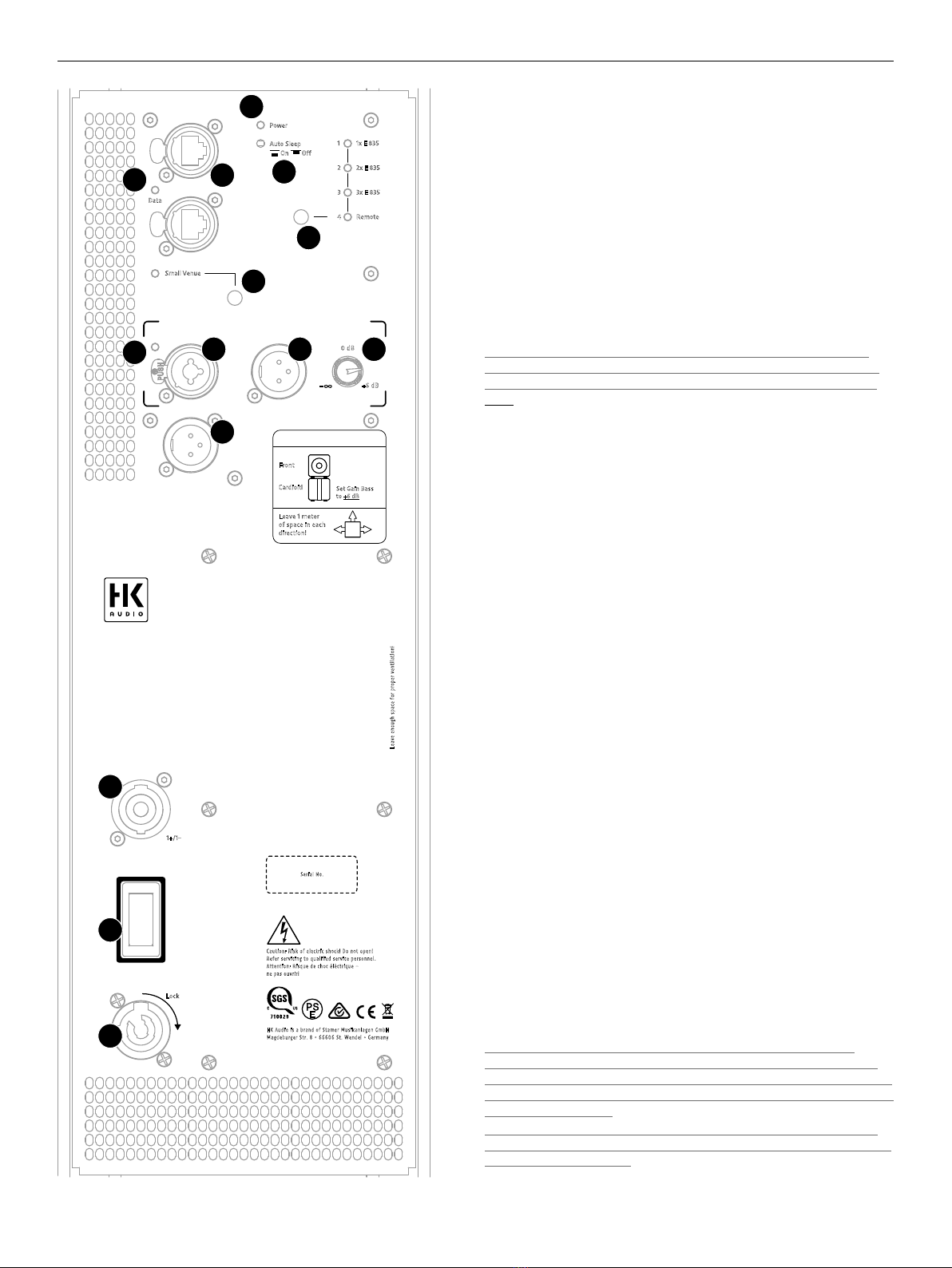
5.2 Operating the LINEAR SUB 1500 A in a Cardioid
Setup
The E 115 Sub D is equipped with a separate Cardioid Out bus. Providing
a signal tuned precisely to the LINEAR SUB 1500 A, this output lets you
configure a cardioid setup with a rearward-facing LINEAR SUB 1500 A
without having to make any other adjustments. However, please be sure to
set the Gain Bass knob on the LINEAR SUB 1500 A to + 6 dB by turning it
clockwise to the far right position, the Phase switch to 0 degrees, and the
X-Over switch to 100 Hz. The E 115 Sub D’s DSP will take care of the rest.
ELEMENTS
E 115 SubD LINEAR SUB
1500 A
0dB
Input
Input
Cardioid Out
Thru
+6 dB
Gain Sub
Heads up: The cardioid setup requires the LINEAR SUB 1500 A to be
placed below the E 115 Sub D. A side-by-side array will not achieve the
desired eect! Also, be sure to always maintain a distance of at least one
meter from walls.
Front
Cardioid
E 115 Sub D
L SUB 1500 A
Set Gain Bass
to +6 dB
Leave 1 meter
of space in each
direction!
Cardioid Setup
When is it a good idea to go with a cardioid setup?
While speakers are able to throw midrange and high frequencies in
directional patterns, low frequencies tend to radiate in all directions.
Excessive bass levels can often be a problem on and behind the stage. And
promoters are increasingly making demands to limit sound systems' low-
end reach, for example, in festival tents at urban venues. Such demands
for limiting low-range frequencies' range are best met with cardioid setups.
With its hardware appointments and filter sets, the E 115 Sub D provides a
fast, easy way to configure eective cardioid setups.
• English • Français• Deutsch • Italiano • Español

ELEMENTS E 115 Sub D 1.1
8
6 Deploying Mid/High Units in
Distributed Setups
You can use the EF 45 base or the wall-mount Install Kit to set up mid/high
units elsewhere rather than stacking them on the subwoofer.
Heads up: HK Audio DSP CONTROL software lets you adjust separately the
delay times for the signals sent to the mid/high units and the subwoofer.
This way, you can place or mount the mid/high units in front of or behind
the subwoofer. Say you want to place the mid/high units two meters
behind the subwoofer because of space constraints: To do this, you would
have to delay the signal sent to the subwoofer by the time it takes to
travel those two meters. Once you set this delay time, you can store it as a
preset on the subwoofer, so the software does not have to be running and
connected to the subwoofer for this configuration to work.
6.1 EF 45
The EF 45 base provides the pedestal for the mid/high units and the
speaker extension poles. Its retractable and extendible feet serve as a
stable, secure platform.
When setting up an ELEMENTS system with the EF 45 base, make sure
the feet are fully extended and locked in placed with the set-screws.
The base has an E-Connect coupler on top and two parallel Speakon
connectors on the rear. Connect mid/high units and speaker extension poles
to the E-Connect, and one of the two Speakon connectors to the Speakon
Mid/High Out on the E 115 Sub D.
Heads up: The EF 45 has two Speakon connectors to allow the signal to be
routed through when you have several mid/high units mounted side by side
on the EF 45/EP 1 or mounted with the Install Kit, for example, to cover very
wide rooms. In this case, make sure the preset selected on the subwoofer
corresponds to the number of mid/high units mounted on each stand or
Install Kit rather than the total number of connected mid/high units.
Heads up: The maximum number of mid/high units still applies in
this case. Do not connect more than three E 835s or six E 435s to the
subwoofer!
6.2 E 435 INSTALL KIT
The ELEMENTS INSTALL KIT consists of two modified E 435 mid/high units
with a mounting bracket. It can be extended with up to two E 835s or four
E 435s. Installation instructions are included with the Install Kit and may be
downloaded from www.hkaudio.com.
7 Optional HK Audio Accessories
1. REAR PROTECTION PLATE
(for the E 115 Sub D and LINEAR SUB 1500 A)
Made of sturdy yet light aluminum, this rear-panel cover splash-proofs
the LINEAR SUB 1500 A’s electronic components and guards against
unauthorized handling in cardioid mode.
2. ELEMENTS BASE BAG
Padded soft case for one EF 45 base
3. ELEMENTS SOFT BAG
Padded soft case for two E 835 units
4. ROLLER BAG E 115 Sub D
Content: One padded soft case for the subwoofer with an integrated dolly
board
The padded roller bag has a sturdy dolly board built in. You can also attach
two bags containing two E 835s / four E 435s and a speaker extension pole
on top to easily transport and quickly assemble an entire system.
5. E 115 Sub D COVER
A padded cover is available as an alternative to the roller bag. It also fits
the LINEAR SUB 1500 A add-on bass bin.
6. 100 mm BLUE SWIVEL CASTERS
The optional swivel castors are mounted to the rear of the E 115 Sub D
subwoofer using the self-locking screws at the corners.
Heads up: The subwoofer does not fit in the ROLLER BAG with the swivel
casters mounted. However, it will fit in the soft cover.

ELEMENTS E 115 Sub D 1.1
9
8 Technical Specifications
E 115 Sub D
Max. SPL @ 10% THD 125 dB half space (40 Hz – X-Over averaged)
Max. SPL peak @ 10% THD 128 dB half space @90 Hz
Frequency response
+/- 3 dB
48 Hz – X-Over
Frequency response -10 dB 44 Hz – X-Over
Power output, Sub 1500 W
Power output, Mid/High
Units
900 W
Amp type Class D
Bass woofer 1x 15", 3" voice coil
Active x-over frequency 160 Hz
Analog ports 1x XLR Combo In bal.,
1x XLR Thru bal.
Speaker Outs 1x E-Connect, 1x Speakon
Cardioid Out 1x XLR
Network port Ethercon RJ45, 1x In, 1x Thru
Filter presets 1x E 835, 2x E 835, 3x E 835, Remote
Remote software DSP CONTROL (Windows, Mac OS)
DSP functions Fully parametric 10-band EQ with variable
filter characteristics, High-Pass Filter, Low-
Pass Filter, Polarity, Level, Delay, Limiter,
Mute
Sampling rate 96 kHz
System latency less than 2.6 ms
Mains connector 1x Powercon NAC3 In, 100–240 V
Power consumption 1 A / 100–240 V nominal according to EN
62368-1
Grips 2x MultiGrip
Housing MDF
Finish Black acrylic enamel
Front grille 2 mm metal grille backed with black acou-
stic foam
Dimensions (WxHxD) 48.5 x 48.5 x 59.5 cm
Weight 29,6 kg / 65.3 lbs
E 835 Mid/High Unit
Power handling,
nominal(RMS)
300 W @ 8 ohms
Axial sensitivity 1W/1m 100 dB Halfspace
Frequency response -10 dB 140 Hz – 20 kHz
Speakers 8 x 3.5" broadband
Directivity 70° horizontal
Corner frequency 140 Hz, 30 dB/oct.
Connectors 1x E-Connect In, 1x E-Connect Out
Dimensions (WxHxD) 11 x 74.5 x 12 cm (excl. E-Connect sleeves)
Weight 4.5 kg / 9.9 lbs
min. 0,86 m
max. 1,52 m
0,94 m
EP 1
EP 2
min. 0,37 m
max. 0,54 m
0,45 m
41 cm
36 cm
46 cm
41,5 cm
12,5 cm
EF 45 for transportation EF 45 in use
• English • Français• Deutsch • Italiano • Español
Version 2.8 08/2019
Wichtige Sicherheitshinweise!
Bitte vor Anschluss lesen!
Dieses Produkt wurde gemäß IEC 62368-1 hergestellt und hat das
Werk in einem sicheren, betriebsfähigen Zustand verlassen. Um
diesen Zustand zu erhalten und um einen gefahrlosen Betrieb zu
gewährleisten, ist es notwendig, dass der Benutzer die Empfehlungen
und Warnhinweise befolgt, die in der Betriebsanleitung zu finden
sind. Bei Einsatz dieses Produktes in Fahrzeugen, Schiffen oder
Flugzeugen, oder in Höhen oberhalb 2000 m Meereshöhe müssen
die entsprechenden Sicherheitsstandards zusätzlich zur IEC 62368-1
beachtet werden.
WARNUNG: Um das Risiko von Feuer oder Stromschlag zu verhüten,
darf dieses Gerät nicht Feuchtigkeit oder Regen ausgesetzt werden.
Öffnen Sie das Gehäuse nicht – im Inneren gibt es keine Bauteile,
die vom Benutzer wartbar sind. Die Wartung darf nur von einem
qualifiziertem Kundendienst durchgeführt werden.
Dieses Symbol, wo immer es erscheint, warnt Sie vor
gefährlicher, nicht isolierter Spannung im Gehäuse – Spannung, die
möglicherweise genügt, eine Stromschlaggefahr darzustellen.
Dieses Symbol, wo immer es erscheint, warnt Sie vor außen
zugänglicher, gefährlicher Spannung. Eine Verbindung zu jeder
Anschlussklemme, die mit diesem Symbol versehen ist, darf nur mit
konfektioniertem Kabel hergestellt werden, dass den Empfehlungen
des Herstellers genügt, oder mit Kabel, das von qualifiziertem
Personal installiert wurde.
Dieses Symbol, wo immer es erscheint, macht Sie auf
wichtige Bedienungs- und Wartungsanweisungen aufmerksam, die in
beiliegenden Unterlagen zu finden sind. Bitte lesen Sie das Handbuch.
Dieses Symbol, wo immer es erscheint, sagt Ihnen: Vorsicht!
Heiße Oberfläche! Um Verbrennungen zu vermeiden, nicht anfassen.
Elektro- und Elektronikgeräte einschließlich Batterien sind
getrennt vom Hausmüll über offizielle Sammelstellen fachgerecht zu
entsorgen.
Bitte lesen Sie diese Anweisungen. Bewahren Sie diese
Anweisungen auf. Befolgen Sie alle Warnhinweise und Anweisungen
auf dem Gerät und in dieser Anleitung.
• Benutzen Sie dieses Gerät nicht in der Nähe von Wasser. Stellen Sie
das Gerät nicht in der Nähe von Wasser, Badewannen, Waschbecken,
Küchenspülen, nassen Stellen, Schwimmbecken oder in feuchten
Räumen auf.
• Stellen Sie keine Gefäße, wie Vasen, Gläser, Flaschen usw., die
Flüssigkeiten enthalten, auf das Gerät.
• Reinigen Sie das Gerät nur mit einem trockenen Tuch.
• Entfernen Sie keine Abdeckungen oder Teile des Gehäuses.
• Die auf dem Gerät angegebene Betriebsspannung muss mit der
örtlichen Spannung der Netzstromversorgung übereinstimmen.
Wenn Sie sich nicht sicher sind, welche Spannung in Ihrem Netz
zur Verfügung steht, konsultieren Sie bitte Ihren Händler oder den
örtlichen Stromversorger.
• Stellen Sie vor Anschluss des Gerätes unbedingt sicher, dass die
Netzversorgungsinstallation über ausreichende Schutzeinrichtungen
gegen Kurzschluss und Erdungsfehler angeschlossener Geräte
verfügt.
• Um das Risiko eines Stromschlags zu verringern, muss die
Erdung des Gerätes beibehalten werden. Verwenden Sie nur das
mitgelieferte Stromführungskabel und behalten Sie die Funktion
der seitlichen, geerdeten Schutzkontakte des Netzanschlusses
immer aufrecht. Stellen Sie sicher, dass das Gerät nur an Steckdosen
angeschlossen wird, die über eine ordnungsgemäß funktionierende
Schutzerde verfügen.
• Schützen Sie das Stromführungskabel vor Betreten und Quetschen,
besonders in der Nähe der Stecker, Gerätesteckdosen – und
dort, wo sie am Gerät austreten! Stromführungskabel sollten
immer vorsichtig behandelt werden. Kontrollieren Sie die
Stromführungskabel in regelmäßigen Abständen auf Einschnitte und
Anzeichen von Abnutzung, besonders in der Nähe des Steckers und
an der Verbindung zum Gerät.
• Benutzen Sie niemals ein beschädigtes Stromführungskabel.
• Ziehen Sie bei Gewittern den Stecker des Gerätes und wenn das
Gerät über einen längeren Zeitraum nicht benutzt wird.
• Dieses Gerät wird nur vollständig von Stromnetz getrennt, wenn der
Stecker vom Gerät oder aus der Steckdose gezogen wird. Das Gerät
sollte so aufgestellt werden, dass das Trennen vom Stromnetz leicht
möglich ist.
• Sicherungen dürfen nur von qualifiziertem Personal gewechselt
werden, und nur unter Verwendung des korrekten Typs und
Nennwerts.
• Alle Wartungsarbeiten sollten nur von qualifiziertem Personal
ausgeführt werden. Wartung ist notwendig, wenn das Gerät auf
irgendeine Weise beschädigt wurde, wie zum Beispiel:
- Wenn das Stromführungskabel oder der Stecker beschädigt oder
abgenutzt ist.
- Wenn Flüssigkeit oder Gegenstände in das Gerät gelangt sind.
- Wenn das Gerät Regen oder Feuchtigkeit ausgesetzt war.
- Wenn das Gerät nicht ordnungsgemäß funktioniert, obwohl die
Bedienungsanleitung beachtet wurde.
- Wenn das Gerät hingefallen ist oder das Gehäuse beschädigt wurde.
• Beim Anschluss von Lautsprechern an dieses Gerät darf die auf dem
Gerät oder in dieser Anleitung angegebene Mindestimpedanz nicht
unterschritten werden. Die verwendeten Kabel müssen entsprechend
den lokalen Regelungen über einen ausreichenden Querschnitt
verfügen.
• Halten Sie das Gerät vom Sonnenlicht fern.
• Installieren Sie das Gerät nicht in der Nähe von Wärmequellen, wie
zum Beispiel Heizkörper, Heizregister, Öfen oder anderen Geräten,
die Hitze erzeugen.
• Dieses Gerät wurde für die Verwendung in gemäßigten Klimazonen
entwickelt. Nicht geeignet zur Verwendung in tropischen Klimazonen.
• Verstopfen Sie nicht die Lüftungsöffnungen. Installieren Sie das
Gerät entsprechend der Anleitung des Herstellers. Das Gerät darf
nicht eingebaut werden – wie zum Beispiel in einen Gestellrahmen,
es sei denn, dass für angemessene Belüftung gesorgt wird.
• Ein kaltes Gerät sollte immer auf die Umgebungstemperatur
erwärmt werden, wenn es in einen Raum transportiert wird.
Es könnte sich Kondensation im Inneren bilden, die das Gerät
beschädigt, wenn es ohne vorherige Erwärmung benutzt wird.
• Stellen Sie keine offenen Flammen, wie brennende Kerzen, auf das
Gerät.
• Das Gerät sollte mindestens 20 cm von Wänden aufgestellt werden.
• Das Gerät darf nur mit Rollwagen, Ständern, Stativen, Tischen
oder Halterungen benutzt werden, die vom Hersteller spezifiziert
sind oder zusammen mit dem Gerät verkauft wurden. Wenn
ein Rollwagen benutzt wird, seien Sie vorsichtig, wenn Sie die
Rollwagen/Geräte-Kombination transportieren, um Verletzungen
durch Umkippen zu vermeiden.
• Verwenden Sie nur Zubehör, das vom Hersteller empfohlen ist. Das
gilt für alle Arten von Zubehör, wie zum Beispiel Schutzabdeckungen,
Transporttaschen, Ständer sowie Wand- und Deckenhalterungen.
Wenn Sie irgendein Zubehör am Gerät anbringen, befolgen Sie
immer die Anleitungen des Herstellers. Benutzen Sie nur die
Befestigungspunkte des Geräts, die vom Hersteller vorgesehen sind.
• Dieses Gerät ist NICHT geeignet für eine Person oder Personen
(einschließlich Kindern) mit eingeschränkten physischen,
sensorischen und geistigen Fähigkeiten, oder für Personen mit
unzulänglicher Erfahrung und/oder Fachkenntnis, um solch ein Gerät
zu bedienen. Kinder unter 4 Jahren sollten stets von diesem Gerät
fern gehalten werden.
• Es sollten keinerlei Gegenstände durch die Gehäuseschlitze
eingeführt werden, da dadurch gefährliche, spannungsführende
Bauteile berührt oder kurzgeschlossen werden können. Dies könnte
zu einer Feuer- oder Stromschlaggefahr führen.
• Dieses Gerät ist imstande, Schalldruckpegel von mehr als 90 dB zu
produzieren. Dies könnte zu einem dauerhaften Hörschaden führen!
Eine Belastung durch extrem hohe Geräuschpegel kann zu einem
dauerhaften Gehörverlust führen. Bei einer anhaltenden Belastung
durch solch hohe Pegel sollte ein Gehörschutz getragen werden.
• Der Hersteller gewährleistet die Sicherheit, Zuverlässigkeit und
Leistung des Gerätes nur unter folgenden Voraussetzungen:
- Einbau, Erweiterung, Neueinstellung, Modifikationen oder
Reparaturen werden vom Hersteller oder autorisiertem Personal
ausgeführt.
- Die elektrische Installation des betreffenden Bereiches entspricht
den Anforderungen der IEC (ANSI) Maßgaben.
- Das Gerät wird entsprechend der Bedienungsanleitung benutzt.
• Dieses Produkt ist auf die Verwendung mit Musik- und Sprach-
signalen optimiert. Verwendung mit Sinus-, Rechteck- oder anderen
Mess-Signalen bei höherem Pegel kann zu ernsten Beschädigungen
des Geräts führen.
Allgemeine Sicherheitshinweise
für Lautsprechersysteme
Befestigungssysteme dürfen ausschließlich für die vom
Hersteller freigegebenen Lautsprechersysteme und mit dem in der
Montageanleitung genannten Montage-Zubehör verwendet werden.
Die Montagehinweise des Herstellers sind dabei unbedingt zu
beachten. Bei unsachgemäßer Montage bzw. Verwendung von nicht
freigegebenem Montage-Zubehör kann die angegebene Belastung
nicht garantiert und keinerlei Haftung seitens des Herstellers
übernommen werden.
Sollten Änderungen an Lautsprechern, an Montage-Zubehör,
Verbindungs- und Befestigungselementen sowie Anschlagmitteln
vorgenommen werden, kann die Tragfähigkeit des Systems nicht
mehr garantiert werden und seitens des Hersteller keinerlei Haftung
übernommen werden.
Reparaturen an sicherheitsrelevanten Bauteilen dürfen nur vom
Hersteller oder Bevollmächtigten durchgeführt werden, andernfalls
erlischt die Betriebserlaubnis.
Die Installation darf ausschließlich durch Sachkundige und nur
an Montagepunkten mit ausreichender Tragfähigkeit, ggf. unter der
Berücksichtigung von Bauauflagen, erfolgen. Das vom Hersteller in der
Montageanleitung vorgeschriebene Befestigungsmaterial (Schrauben,
Dübel, etc.) muss verwendet werden. Schraubverbindungen müssen
durch geeignete Maßnahmen gegen Lösen gesichert sein.
Ortsfeste oder mobile Installationen (hier Lautsprecher
inkl. Montagezubehör) müssen durch zwei unabhängig voneinander
wirkende Einrichtungen gegen Herabfallen gesichert sein. Lose
Zusatzteile oder sich lösende Teile müssen durch geeignete
Einrichtungen aufgefangen werden können. Bei Verwendung von
Verbindungs- und Befestigungselementen sowie Anschlagmitteln sind
die nationalen Vorschriften zu beachten. Hinsichtlich der Bemessung
der Sicherungsmittel sind mögliche dynamische Belastungen
(Ruckkräfte) mit zu berücksichtigen.
Bei Stativen ist vor allem die maximale Traglast zu beachten.
Außerdem sind die meisten Stative aus konstruktiven Gründen nur
für das Tragen von genau zentrischer Belastung zugelassen. Stative
müssen standsicher aufgestellt werden. Stative sind durch geeignete
Maßnahmen zusätzlich zu sichern, wenn zum Beispiel:
- ihre Aufstandfläche keinen sicheren Stand zulässt,
- ihre Höhen die Standsicherheit einschränken,
- mit zu hohem Winddruck zu rechnen ist,
- damit zu rechnen ist, dass sie durch Personen umgestoßen werden.
Besondere Maßnahmen können auch zur Vorsorge gegen gefährdendes
Verhalten von Zuschauern erforderlich werden. Stative dürfen nicht
in Flucht- und Rettungswegen aufgestellt werden. Bei Aufstellung
in Verkehrswegen ist auf die erforderliche Breite der Wege und
auf ordnungsgemäße Absperrung sowie Kennzeichnung zu achten.
Beim Auf- und Absetzen ist eine besondere Gefährdung gegeben.
Hierzu sind geeignete Hilfsmittel zu verwenden. Es sind hierbei die
nationalen Vorschriften zu beachten.
Während der Montage ist geeignete
Schutzausrüstung (insbesondere Kopfschutz, Handschuhe und
Sicherheitsschuhe) zu tragen und es sind nur geeignete Aufstiegshilfen
(Leitern, Gerüste, etc.) zu verwenden. Die Verantwortung dafür liegt
alleine beim ausführenden Installationsbetrieb.
ACHTUNG! Nach der Montage ist die Aufhängung des Systems
aus Halterung und Lautsprecher auf sichere Befestigung zu überprüfen.
Der Betreiber von Lautsprechersystemen (ortsfest oder mobil) ist
verpflichtet, alle Systemkomponenten unter Berücksichtigung der
jeweils nationalen Regelungen regelmäßig zu überprüfen bzw. prüfen
zu lassen und mögliche Schäden unverzüglich beseitigen zu lassen.
Weiterhin raten wir dringend zu einer ausführlichen Dokumentation
aller Überprüfungsmaßnahmen in Prüfbüchern o.ä.
Insbesondere die Lastaufnahmepunkte geflogener Systeme sollten
hier mit ausreichenden Sicherheitsreserven dimensioniert werden. Es
sind hierbei die nationalen Vorschriften zu beachten.
Professionelle Lautsprechersysteme sind in der Lage,
gesundheitsschädliche Schallpegel zu erzeugen. Selbst die Einwirkung
scheinbar harmloser Schallpegel über einen längeren Zeitraum
kann zu bleibenden Schäden am Gehör führen (ab ca. 95dBA
SPL)! Daher raten wir für alle Personen, die durch den Betrieb von
Lautsprechersystemen dem Einfluss hoher Schallpegel ausgesetzt
sind, zum Tragen von professionellem Gehörschutz (Ohrstöpsel oder
Kapselgehörschutz).
Hersteller: Stamer Musikanlagen GmbH, Magdeburger Str. 8,
66606 St. Wendel, Deutschland

ELEMENTS E 115 Sub D 1.1
11
Willkommen in der HK Audio Familie!
Vielen Dank, dass Sie sich für ein Markenprodukt aus unserem Hause ent-
schieden haben, das mit größter Sorgfalt für Sie entwickelt und gefertigt
wurde.
Auch wenn Sie bereits eingehende Erfahrungen mit Beschallungsan-
lagen gesammelt haben – bei diesem Produkt wird es trotzdem einige
Dinge geben, die neu für Sie sind. Legen Sie deshalb diese Bedienungs-
anleitung nicht ungelesen beiseite und bewahren Sie sie zur späteren
Verwendung auf.
Wir wünschen Ihnen allzeit besten Sound!
Ihr HK Audio Team
Garantie
Nutzen Sie die komfortable Online-Registrierung über www.hkaudio.com.
http://warranty.hkaudio.com
Die Registrierung ist nur gültig, wenn sie innerhalb von 30 Tagen ab
Kaufdatum erfolgte.
HK AUDIO
Technischer Service
Postfach 1509
66595 St. Wendel, Deutschland
Fax: +49 6851 905 100
Hinweis: Die Funktionalität dieses Produkts kann durch starke
elektromagnetische Felder oder elektrostatische Entladungen gestört
werden. In diesem Fall kann durch Ausschalten und erneutes Einschalten
die Funktionalität wieder hergestellt werden. Falls dies nicht hilft, muss
das Gerät von der Störquelle entfernt werden.
1 Allgemeines
Lieferumfang
Bitte überprüfen Sie beim Auspacken Ihrer ELEMENTS E 115 Sub D Laut-
sprecherbox den Lieferumfang auf Vollständigkeit. Im Lieferumfang sind
die Bedienungsanleitung und ein Powercon-Netzkabel enthalten.
Die Systemkomponenten
Wichtiger Hinweis: Bitte bachten Sie, dass der Systembass E 115 Sub D
nur mit passiven HK Audio ELEMENTS-Komponenten betrieben werden
darf.
Achtung: Werden fremde Geräte an den Speakon-Ausgang angeschlos-
sen, können diese und die Elektronik des Sysstembasses zerstört
werden.
Inbetriebnahme
Vergewissern Sie sich, dass der E 115 Sub D beim Aufbau ausgeschaltet ist,
ansonsten droht Gefahr einer Beschädigung! Bauen Sie immer zuerst das
komplette System samt Verkabelung auf und schalten Sie ihn erst danach
als letztes ein. Für das Abbauen gilt: Schalten Sie den ELEMENTS System-
bass immer als erstes aus.
ELEMENTS E 115 Sub D
• English • Français• Deutsch • Italiano • Español
ELEMENTS E 115 Sub D 1.1
12
Leave enough space for proper ventilation!
ELEMENTS
E 115 SubD
MADE IN GERMANY
Preset
Thru
In
1x E 835
Power
Auto Sleep
2x E 835
3x E 835
Remote
1
2
3
4
On Off
Ethernet
0dB
Input
Cardioid Out
Thru
Data
Serial No.
Mains Input
100-240 V~
50-60 Hz
1.9 A @ 1/8
output power
Caution: Risk of electric shock! Do not open!
Refer servicing to qualified service personnel.
Attention: Risque de choc élèctrique –
ne pas ouvrir!
HK Audio is a brand of Stamer Musikanlagen GmbH
.BHEFCVSHFS4USŦ4U8FOEFMŦ(FSNBOZ
Power
Mid/High Out
E 835
Lock
1+/1–
+6 dB
Small Venue
Front
Cardioid
E 115 Sub D
L SUB 1500 A
Set Gain Bass
to +6 dB
Leave 1 meter
of space in each
direction!
Cardioid Setup
Gain Sub
1
6
5
4
10
11
12
13
14
7
9
2
8
3
2 Anschlüsse und Bedienelemente
●
1Input
XLR/Klinke-Kombibuchse, symmetrischer Eingang für analoge Signale.
●
2Thru
Symmetrischer, parallel zur Eingangsbuchse geschalteter XLR-Ausgang
dient zur Weiterleitung des am Input anliegenden Eingangssignals, unab-
hängig davon, ob die Elektronik eingeschaltet ist oder nicht.
●
3Gain Sub
Der Gain Sub-Regler regelt die Vorverstärkung des am Input anliegenden
Signals.
Hinweis: Mit diesem Regler wird die Lautstärke des E 115 Sub D ange-
passt, die angeschlossenen Mid/High-Units werden von diesem Regler
nicht beeinflusst. Als Ausgangsbasis empfehlen wir die Mittelstellung
0dB.
●
4Input/Limiter-LED
Diese LED leuchtet grün wenn ein Signal am Input anliegt – und rot sobald
der Limiter aktiv ist oder der Eingang übersteuert wird. Ein kurzzeitiges
rotes Aufleuchten der LED zeigt das Arbeiten des Limiters bei Pegelspitzen
an. Leuchtet sie dauerhaft rot, muss der Pegel reduziert werden.
●
5Cardioid Out
Dieser Ausgang dient zum Anschluss des passenden Subwoofers HK Audio
LINEAR SUB 1500 A zum Betrieb im Cardioid-Aufbau, siehe Kapitel 5.2.
●
6Ethernet In /Thru
Die beiden Ethercon-Buchsen dienen zur Integration in ein Netzwerk. Sie
sind kompatibel mit RJ45-und Ethercon (NE8 MX, NE8 MX6, NE8 MC)-
Steckern. Nutzen Sie die Ethernet Thru-Buchse zum Weiterschleifen des
Netzwerk-Signals.
Bitte verwenden Sie zum Schutz gegen elektromagnetische Störungen
stets S/STP- oder S/FTP-Kabel. Wir empfehlen die Verwendung von
CAT6-Kabeln. Die Integration in ein Netzwerk, Funktionen des Remote-
Controlling sowie die Nutzung von Audio-Streaming sind in einer separaten
Bedienungsanleitung beschrieben, die im Download-Bereich zu ELEMENTS
auf www.hkaudio.com zur Verfügung steht. Eine Kurzbeschreibung der
DSP-Funktionen finden Sie unter ●
8Preset.
●
7Data
Diese LED leuchtet orange, wenn Daten über die Netzwerkbuchse fließen.
●
8Preset
Über den Preset-Wahltaster lassen sich die voreingestellten Werks-Presets
sowie ein über die Remote-Software DSP CONTROL konfigurierbares User-
Preset abrufen. Durch einmaliges Tippen auf den Wahltaster können Sie
durch die Presets 1 bis 4 scrollen.
Die Nutzung von User-Presets (4 Remote) ist in einer separa-
ten Bedienungsanleitung beschrieben, die im Download-Bereich zu
ELEMENTSD auf www.hkaudio.com zur Verfügung steht.
Hinweis: Über die Auswahl des Presets wird der Frequenzgang des
System-Basses auf den Frequenzgang der angeschlossenen Mid/High-
Units angepasst. Diese manuelle Einstellung ist zwingend notwendig, da
die Endstufe nicht automatisch erkennen kann, wie viele Mid/High-Units
angeschlossenen sind.
Achtung: Die am Filter-Schalter angegebenen Zahlen gelten immer für
die Mid/High-Unit E 835. Bei Verwendung des Modells E 435 ist die ange-
geben Zahl zu verdoppeln.

ELEMENTS E 115 Sub D 1.1
13
Preset 1: 1x E 835 (2x E 435)
Preset 2: 2x E 835 (4x E 435)
Preset 3: 3x E 835 (6x E 435)
Hinweis: auch eine Mischbestückung ist möglich, z.B. zwei E 835 + zwei
E 435, wählen Sie dann Preset 3. Sogar die Nutzung einer ungeraden
Anzahl von E 435 ist möglich, z.B. zwei E 835 + ein E 435, oder auch drei
E435. Wählen Sie in diesen Fällen die nächstkleinere Preset-Nummer
aus, und korrigieren eventuell die Höhenwiedergabe mittels Mischpult-
EQ, oder passen den Frequenzgang über die Sofware HK Audio DSP
CONTROL an.
E 835 E 835 E 435
E 435 E 435 E 435
Preset
2
E 835 E 835 E 835
Preset
3
E 835 E 835
Preset
2
Preset
1
E 435 E 435
Preset
1
E 835
Preset
1
1x
E 835
2x
E 435
=
Preset 4: Remote
Hier kann eine zuvor über DSP CONTROL gespeicherter User-Preset abge-
rufen werden. Der Systembass muss dazu nicht mit der Remote-Software
verbunden sein.
Über die Remote-Software DSP CONTROL zur Verfügung stehende DSP-
Funktionen, die als User-Preset gespeichert werden können: Vollparamet-
rischer 10-Band EQ mit wählbarer Filter-Charakteristik pro Frequenzband,
High-Pass- und Low-Pass-Filter mit jeweils wählbarer Filter-Charakteristik,
Limiter, Delay, Pegel, Mute.
Screenshot der Remote-Software DSP CONTROL, welche im Download-Bereich der ELEMENTS-Produkte
auf www.hkaudio.com kostenlos zur Verfügung steht.
●
9Small Venue
Der Frequenzgang Ihres ELEMENTS-Systems ist für die Beschallung von
größeren Räumen optimiert, bei denen eine hohe Reichweite der Lautspre-
cher nötig sind.
Soll das System für den Einsatz in kleineren Räumen genutzt werden,
aktivieren Sie mit diesem Schalter die Frequenzoptimierung "Small Venue"
(rote LED leuchtet). Dann klingt das System auch auf kurze Distanz ausge-
wogen und angenehm transparent.
●
10 Mid/High Out
Der Speakon-Ausgang dient zum Anschluss von ELEMENTS Mid/High-Units
über den als Zubehör erhältlichen Standfuß EF 45 oder zur Weiterleitung an
ein ELEMENTS Install Kit.
Verwenden Sie hierzu handelsübliche Speakon NL2-Kabel. Speakon-Kabel
werden durch Einstecken und Drehen der Arretierung im Uhrzeigersinn
verbunden, eine Drehung gegen den Uhrzeigersinn löst die Verbindung.
Achtung: Der Mid/High-Ausgang ist parallel zum E-Connect (15) auf der
Oberseite des E 115 Sub D geschaltet, er darf nur benutzt werden, wenn
E-Connect nicht in Betrieb ist.
Achtung: Werden fremde Geräte an den Speakon-Ausgang angeschlos-
sen, können diese und die Elektronik des Sysstembasses zerstört
werden.
●
11 Mains Input
Der Netzsanschluss ist als Powercon-Buchse ausgeführt, ein entsprechen-
des Netzkabel ist im Lieferumfang enthalten. Achten Sie darauf, dass das
Powercon-Kabel durch Drücken und Drehen im Uhrzeigersinn einrastet und
verriegelt. Zum Entriegeln ziehen Sie die Verriegelungsvorrichtung des
Powercon-Steckers in Richtung des Kabels und drehen Sie ihn gegen den
Uhrzeigersinn.
●
12 Power
Der Netzschalter ist als Kippschalter ausgeführt. In Stellung Power ist die
Elektronik eingeschaltet, im ausgeschalteten Zustand ist die Elektronik
komplett vom Netz getrennt.
●
13 Power-LED
Sobald die Elektronik mit Spannung versorgt wird, leuchtet diese LED grün.
●
14 Auto Sleep
Über diesen versenkten Schalter kann die energiesparende Auto-Sleep-
Funktion ein- und ausgeschaltet werden. Ab Werk ist Auto Sleep aktiviert
(Schalter gedrückt). Diese Funktion versetzt die Elektronik in den Auto
Sleep-Modus wenn über einen Zeitraum von 4,5 Stunden weder ein Signal
anliegt, noch Daten über die Netzwerk-Buchsen eingehen oder Taster
und Regler an der Elektronik bedient werden. Ein Wieder-Aktivieren der
Lautsprecherbox ist nur durch Aus- und Einschalten des Netzschalters oder
durch Anlegen eines analogen Audiosignals am Eingang möglich.
●
15 E-Connect
Auf der Oberseite des E 115 Sub D befindet sich der ELEMENTS E-Connect-
Ausgang. An diesem signalführenden Anschluss werden Mid/High-Units
E 835 und E 435 und die Distanzstangen EP 1 und EP 2 angeschlossen. Es
können bis zu drei Mid/High-Units E 835 bzw. bis zu sechs E 435 betrieben
werden, siehe auch Kapitel 3 „Aufstellen und Verbinden der Säulenkompo-
nenten“.
Achtung: Der E-Connect ist parallel zum Mid/High-Ausgang auf der
Rückseite (Speakon) geschaltet, er darf nur benutzt werden, wenn der
Speakon-Out nicht in Betrieb ist.
• English • Français• Deutsch • Italiano • Español

ELEMENTS E 115 Sub D 1.1
14
3 Aufstellen und Verbinden der Säulen-
komponenten
3.1 E-Connect
E-Connect erlaubt eine sichere und schnelle Signalverbindung zwischen
den Passiv-Komponenten des ELEMENTS Systems ohne Kabel. E-Connect
stellt den elektrischen und mechanischen Anschluss zwischen den Mid/
High-Units E835, der Distanzstange EP 1/EP 2 und auch zum Stand-Fuß
EF45 her.
3.2 Verbindung der Säulen-Komponenten
Halten Sie die Komponenten so, dass die jeweiligen Rohrverbindungen
übereinander stehen. Zur festen Verbindung stecken Sie die Rohrverbin-
dung des oberen Teils vollständig in die Justierhülse des unteren Teils.
Achten Sie darauf, dass der Arretierknopf auf der Rückseite in das entspre-
chende Justierloch einrastet.
Push!
Zum Lösen einer Verbindung halten Sie den Arretierknopf in der Rohrver-
bindung gedrückt und ziehen dann die Komponenten auseinander.
Pull!
Achtung: Achten Sie immer bei der Aufstellung des Systems auf einen
waagerechten und befestigten Untergrund.
4 Aufstellung des Systems
4.1 Vertikale Ausrichtung der Mid/High-Säulen
Die richtige Höhe
Bei Line-Array-Systemen wie ELEMENTS wird die Abstrahlung verti-
kal gebündelt. Achten Sie bei der Aufstellung deshalb darauf, dass der
Mittelpunkt einer Lautsprecher-Zeile immer etwa in Kopfhöhe der Zuhörer
justiert ist.
Um die Höhe einer Zeile anzupassen sind stufenlos verstellbare und durch
einen Drehverschluss arretierbare Distanzstangen in zwei verschiedenen
Längen optional erhältlich: EP 1 / EP 2
Sie sorgen in kleineren Konfigurationen für einfachen, schnellen Aufbau. Sie
bieten mittels E-Connect eine kabellose Signalführung für die aufgesteck-
ten Mid/High-Units. Die genauen Maße der beiden Distanzstangen finden
Sie in den technischen Daten.
Achtung: Verbinden Sie niemals zwei Distanzstanzstangen miteinander!
4.2 Horizontale Ausrichtung der Mid/High-Säulen
Die horizontale Abstrahlung einer Mid/High-Säule beträgt etwa 70°. Drehen
Sie je nach Anwendung die Säulen entsprechend auf die zu beschallende
Fläche ein, um die Schallenergie eektiver zu nutzen.
70°
Ein perfektes Abstrahlverhalten erhält man, wenn alle miteinander verbun-
denen Komponenten im gleichen Winkel abstrahlen. ELEMENTS bietet mit
der Locking Wedge (im Lieferumfang enthalten) die Möglichkeit die Mid/
High-Units horizontal zu arretieren. Dann ist ein Verdrehen der Komponen-
ten ausgeschlossen.
Push!
Die Locking Wedge wird einfach in den dafür vorgesehenen Schaft einge-
clipst. Zum Herauslösen muss leichter Druck auf die Mittelplatte ausgeübt
werden.

ELEMENTS E 115 Sub D 1.1
15
4.3 Maximalausbau
Ihr E 115 Sub D kann in folgender maximaler Konfiguration betrieben wer-
den:
1x
E 835
E 835
E 115 Sub E
E 835 E 835
2x
E 435
=
5 Bass-Erweiterung und Cardioid-Betrieb
mit HK Audio LINEAR SUB 1500 A
Der aktive Bass HK Audio LINEAR SUB 1500 A passt akustisch, mechanisch
und optisch ideal als Bass-Erweiterung zum E 115 Sub D. Bevor sie den
LINEAR SUB 1500 A anschließen, achten Sie darauf, dass dessen Phasen-
Schalter sich in der 0 Grad-Stellung befindet und der Schalter X-Over Bass
auf 100 Hz steht. Die Stellung des Schalters Configuration ist nicht relevant,
da er lediglich den Pegel des Line Out Mid/High des LINEAR SUB 1500 A
beeinflusst.
Der E 115 Sub D bietet zwei verschiedene Ausgänge, um den LINEAR SUB
1500 A entweder als Erweiterung, oder im Cardioid-Setup zu betreiben:
5.1 LINEAR SUB 1500 A als Bass-Erweiterung
Schließen Sie den LINEAR SUB 1500 A an den Thru des E 115 SUB A an. Er
erhält dann das unbearbeitete Signal, das am Eingang des E 115 Sub D an-
liegt. Die Pegel-Anpassung erfolgt über den Gain Bass-Regler des LINEAR
SUB 1500 A. In diesem Fall kann der LINEAR SUB 1500 A sowohl unter, also
auch neben den E 115 Sub D gestellt werden.
ELEMENTS
E 115 SubD LINEAR SUB
1500 A
0dB
Input
Input
Cardioid Out
Thru
+6 dB
Gain Sub
5.2 Cardioid-Betrieb mit dem LINEAR SUB 1500 A
Der E 115 Sub D verfügt über einen separaten Cardioid Out. Dieser Ausgang
liefert ein auf den LINEAR SUB 1500 A präzise abgestimmtes Signal, um
ohne zusätzliche Einstellungen einen Cardiod-Betrieb mit einem nach
hinten gerichteten LINEAR SUB 1500 A zu realisieren. Achten Sie aber
bitte darauf, dass der Gain Bass-Regler des LINEAR SUB 1500 A auf + 6 dB
(Rechtsanschlag), der Phasen-Schalter in Stellung 0 Grad, und der X-Over-
Schalter auf 100 Hz steht. Alles Weitere übernimmt der DSP des E 115 Sub
D.
ELEMENTS
E 115 SubD LINEAR SUB
1500 A
0dB
Input
Input
Cardioid Out
Thru
+6 dB
Gain Sub
Achtung: Im Cardioid-Betrieb muss der LINEAR SUB 1500 A zwingend
unter den E 115 Sub D platziert werden, ein Aufbau nebeneinander erzielt
nicht die gewünschte Wirkung! Desweiteres ist darauf zu achten, dass
mindestens 1 Meter Abstand zu Wänden gewährleistet ist.
Front
Cardioid
E 115 Sub D
L SUB 1500 A
Set Gain Bass
to +6 dB
Leave 1 meter
of space in each
direction!
Cardioid Setup
Wann macht ein Cardioid-Aufbau Sinn?
Während mittlere und hohe Frequenzen gerichtet abgestrahlt werden kön-
nen, breiten sich tiefe Frequenzen kugelförmig aus. Das führt oft zu einem
unangenehmen Übermaß an Tiefbässen auf und hinter der Bühne. Auch
wird es zunehmend üblich, dass Veranstalter genaue Vorgaben zur Schall-
verteilung machen, z.B. für Festzelte in Innenstädten. Das ist im Bassbe-
reich am eektivsten mit Cardioid-Technik umzusetzen (Auslöschung der
nach hinten abgestrahlten Frequenzen). Der E 115 Sub D erfüllt deshalb
sowohl mechanisch als auch mit den zur Verfügung stehenden Filtersätzen
die Voraussetzungen, schnell und einfach wirkungsvolle Cardioid-Setups zu
realisieren.
• English • Français• Deutsch • Italiano • Español

ELEMENTS E 115 Sub D 1.1
16
6 Dezentrale Nutzung der Mid/High-
Units
Die Mid/High-Units können mittels Standfuß EF 45 oder dem INSTALL KIT
für Wandmontage auch dezentral, das heißt, nicht unmittelbar auf dem
Systembass montiert, betrieben werden.
Hinweis: mit Hilfe der Software HK Audio DSP CONTROL kann eine zeitver-
zögerte Signalwiedergabe für die Mid/High-Units und den System-Bass
separat eingestellt werden. Dies erlaubt eine Aufstellung bzw. Montage der
Mid/High-Units vor oder hinter dem Systembass. Werden aus räumlichen
Gründen z.B, die Mid/High-Units mit zwei Meter Abstand hinter dem Bass
aufgestellt, muss die Signalwiedergabe des Basses um eine zwei Metern
entsprechende Laufzeit verzögert werden. Die eingestellte Laufzeitverzö-
gerung kann als Preset im System-Bass gespeichert werden, das heißt, für
den Betrieb braucht die Software nicht mit dem System-Bass verbunden zu
sein.
6.1 EF 45
Der Standfuß dient als Basis für die Mid/High-Units und die Distanzstan-
gen. Die ausziehbaren Fußverlängerungen sorgen für sicheren und festen
Stand.
Achten Sie beim Aufbau eines ELEMENTS-Systems mit dem Standfuß
EF 45 darauf, dass die Ausstellfüße immer komplett ausgefahren und
durch die Feststellschrauben fixiert sind.
Der Standfuß verfügt über einen E-Connect auf der Oberseite und zwei
parallel geschaltete Speakon-Anschlüsse an dem nach hinten zeigenden
Ausläufer. Verbinden Sie Mid/High.-Units und Distanzstangen mit dem
E-Connect, und einen der beiden Speakon-Anschlüsse mit dem ebenfalls als
Speakon ausgeführtebn Mid/High-Out des E 115 Sub D.
Hinweis: der EF 45 verfügt über zwei Speakon-Anschlüsse um eine Wei-
terleitung des Sitgnals zu ermöglichen, wenn mehrerer nebeneinander auf
EF 45/EP 1 montierten oder über das Install-Kit montierte Mid/High-Units
verwendet werden sollen, z.B. in sehr breiten Räumen, Achten Sie dann
darauf, dass das am System-Bass eingestellte Preset der Anzahl der Mid/
High-Units pro Standfuß bzw. Install-Kit entspricht, nicht der Gesamtan-
zahl der angeschlossenen Mid/High-Units,
Achtung: die Gesamtanzahl am Systembass betriebenen Mid/High-Units
darf auch in dieem Fall drei E 835 bzw. sechs E 435 nicht übersteigen!
6.2 E 435 INSTALL KIT
Das ELEMENTS Install Kit besteht aus zwei modifizierten E 435-Mid/High-
Units inklusive Montagebügel und kann mit bis zu zwei E 835 bzw. vier
E435 erweitert werden. Eine Montage-Anleitung liegt dem Install-Kit bei
und steht auf www.hkaudio.com zum Download bereit.
7 Optionales Zubehör von HK Audio
1. REAR PROTECTION PLATE
(für E 115 Sub D und LINEAR SUB 1500 A)
Die aus stabilem aber leichtem Aluminium gefertigte Rear Protection Plate
schützt die Elektronik nicht nur vor Spritzwasser, sie verhindert bei Nut-
zung des LINEAR SUB 1500 A im Cardioid-Betrieb auch unbefugten Zugri
auf dessen Elektronik.
2. ELEMENTS BASE BAG
Inhalt: 1x gepolsterte Transporttasche für 1x Standfuß EF 45
3. ELEMENTS SOFT BAG
Inhalt: 1x gepolsterte Transporttasche für 2x E 835
4. ROLLER BAG E 115 Sub D
Inhalt: 1x gepolsterte Subwoofer-Hülle mit integriertem Rollbrett
Der gepolsterte Roller-Bag verfügt über ein stabiles, eingebautes Rollbrett,
und bietet zusätzlich die Möglichkeit bis zu zwei Tragetaschen mit je zwei
E 835 / vier E 435 und Distanzstange auf der Oberseite zu fixieren, Dadurch
ist einfachsten Transport und schneller Aufbau eines kompletten Systems
gewährleistet.
5. SCHUTZHÜLLE E 115 Sub D
Als Alternative zum Roller-Bag ist eine gepolsterte Schutzhülle erhältlich.
Diese passt auch für den Erweiterungsbass LINEAR SUB 1500 A.
6. LENKROLLEN 100 mm blau
Die optional erhältlichen Lenkrollen können auf der Rückseite des E 115
Sub D mittels der in den Ecken vorhandenen Sperrzahnschrauben befestigt
werden.
Achtung! Mit montierten Lenkrollen kann der ROLLER BAG nicht mehr
verwendet werden. In diesem Fall eignet sich die passende gepolsterte
Schutzhülle.

ELEMENTS E 115 Sub D 1.1
17
8 Technische Daten
E 115 Sub D
Max. SPL @ 10% THD 125 dB Halfspace (40 Hz – X-Over gemittelt)
Max. SPL peak @ 10% THD 128 dB Halfspace @90 Hz
Frequenzgang +/- 3 dB 48 Hz – X-Over
Frequenzgang -10 dB 44 Hz – X-Over
Endstufenleistung Sub 1500 W
Endstufenleistung Mid/
High Units
900 W
Endstufentyp Class D
Basslautsprecher 1x 15", 3" Schwingspule
Trennfrequenz aktiv 160 Hz
Anschlüsse analog 1x XLR/Klinke-Kombi In symm.,
1x XLR Thru symm.
Lautsprecher-Ausgänge 1x E-Connect, 1x Speakon
Cardioid-Ausgang 1x XLR
Netzwerkanschluss Ethercon RJ45, 1x In, 1x Thru
Filter-Presets 1x E 835, 2x E 835, 3x E 835, Remote
Remote-Software DSP CONTROL (Windows, Mac OS)
DSP-Funktionen Vollparametrischer 10-Band EQ mit varia-
bler Filter-Charakteristik, High-Pass-Filter,
Low-Pass-Filter, Polarität, Level, Delay,
Limiter, Mute
Sampling-Rate 96 kHz
Systemlatenz 2,6 ms
Netzanschluss 1x Powercon NAC3 In, 100–240 V
Leistungsaufnahme 1 A / 100–240 V Nenn-Stromverbrauch nach
EN 62368-1
Grie 2x MultiGrip
Gehäuse MDF
Oberfläche Acryllack, schwarz
Frontgitter 2 mm Metallgitter mit schwarzem Akustik-
schaumsto
Abmessungen (BxHxT) 48.5 x 48.5 x 59.5 cm
Gewicht 29,6 kg / 65,3 lbs
E 835 Mid/High Unit
Belastbarkeit nominal
(RMS)
300 W @ 8 Ohm
Empfindlichkeit 1W/1m 100 dB Halfspace
Frequenzgang -10 dB 140 Hz – 20 kHz
Lautsprecher 8x 3,5"-Breitbandlautsprecher
Abstrahlung 70° horizontal
Trennfrequenz 140 Hz, 30 dB/Okt.
Anschlüsse 1x E-Connect In, 1x E-Connect Out
Abmessungen (BxHxT) 11 x 74,5 x 12 cm (exkl. E-Connect-Stutzen)
Gewicht 4,5 kg / 9,9 lbs.
min. 0,86 m
max. 1,52 m
0,94 m
EP 1
EP 2
min. 0,37 m
max. 0,54 m
0,45 m
41 cm
36 cm
46 cm
41,5 cm
12,5 cm
EF 45 for transportation EF 45 in use
• English • Français• Deutsch • Italiano • Español
Version 2.8 08/2019
Consignes de sécurité importantes! A lire avant
de se connecter!
Ce produit a été construit conformément à la norme IEC 62368-1 par
le fabricant et a quitté l’usine en bon état de marche. Pour garantir
son intégrité et un fonctionnement sans risque, l’utilisateur se doit
de suivre les conseils et les avertissements préconisés dans cette
notice d’utilisation. En cas d’utilisation de ce produit dans un véhicule
terrestre, un navire ou un avion, ou encore à une altitude supérieure à
2000 mètres, il convient de prendre en considération les normes de
sécurité suivantes, en plus de la norme IEC 62368-1.
ATTENTION: Afin d’éviter tout risque d‘incendie et d‘électrocution,
n‘exposez pas cet appareil à l’humidité ou à la pluie. N’ouvrez pas
le boîtier; les pièces se trouvant à l’intérieur ne nécessitent pas
d’entretien de la part des utilisateurs. Adressez-vous à un spécialiste
qualifié pour procéder à l‘entretien de l‘appareil.
Ce symbole, quel que soit l’endroit où il apparaît, vous signale
des pièces sous tension non isolées dans le boîtier. Une tension
suffisante pour présenter un risque d’électrocution.
Ce symbole, quel que soit l’endroit où il apparaît, vous signale
des pièces sous tension accessibles depuis l’extérieur du boîtier. Tous les
câbles extérieurs raccordés à un composant marqué de ce symbole
doivent être de type préfabriqués et conformes aux spécifications du
fabricant ou doivent avoir été installés par des spécialistes qualifiés.
Ce symbole, quel que soit l’endroit où il apparaît, vous signale
des instructions importantes relatives à l’utilisation ou l’entretien de
l’appareil à lire dans les documents l’accompagnant. Lisez la notice
d’utilisation.
Ce symbole, quel que soit l’endroit où il apparaît, vous signale
un risque de brûlure dû à une surface chaude. Ne touchez pas cette
surface afin d’éviter de vous brûler.
Tous les appareils électriques et électroniques y compris les
piles doivent être éliminés séparément des déchets ménagers auprès des
points de collecte officiels prévus à cet effet.
Lisez ces instructions. Conservez ces instructions. Prenez en
compte tous les avertissements et toutes les instructions mentionnés
sur le produit ou dans cette notice d’utilisation.
• N’utilisez pas ce produit à proximité de l’eau. Ne le placez pas près de
l’eau, d’une baignoire, d’un bassin, d’un évier, d’une surface humide,
d’une piscine ou d’une pièce humide.
• Ne mettez pas d’objet contenant du liquide sur l’appareil, par exemple,
un vase, un verre ou une bouteille, etc.
• Nettoyez-le exclusivement avec un chiffon sec.
• N’enlevez pas le boîtier, ne serait-ce que partiellement.
• La tension de fonctionnement de l’appareil doit être réglée de manière
à correspondre à la tension d’alimentation de l’endroit où vous vous
trouvez. Si vous n’êtes pas sûr de connaître la tension d’alimentation,
demandez à votre revendeur ou à la compagnie d’électricité locale.
• Avant de brancher l’appareil, assurez-vous systématiquement que
l’installation électrique (alimentation) dispose de systèmes de
protection suffisants contre les courts-circuits et les erreurs de mise à
la terre des appareils raccordés.
• Afin de réduire le risque d’électrocution, vous ne devez jamais
supprimer la mise à la terre de l’appareil. Utilisez uniquement le câble
d’alimentation fourni avec le produit et maintenez la broche centrale
de la prise (mise à la terre) en état de fonctionnement. Ne négligez
pas la sécurité offerte par les prises polarisées ou avec mise à la terre.
Assurez-vous que l’appareil est bien raccordé à une prise disposant
d’une terre de protection et que celle-ci est en ordre de marche.
• Protégez le câble d’alimentation afin d’éviter que quelqu’un marche
dessus ou qu’il soit pincé, notamment près de la prise, de la prise
murale ou à la sortie de l’appareil même! Les câbles d’alimentation
doivent être tout le temps maniés avec précaution. Vérifiez
régulièrement que le câble n’est pas fendu ou qu’il ne présente pas de
signe d’usure, en particulier près de la prise et à la sortie de l’appareil.
• N’utilisez jamais de câble d’alimentation usé.
• Débranchez l’appareil en cas d’orage ou si vous ne l’utilisez pas
pendant une longue période.
• Débranchez l’appareil uniquement en le tenant par la prise au niveau
de la prise murale ou de la rallonge. L’appareil doit être placé de telle
manière à ce qu’il puisse être débranché facilement à tout moment.
• Les fusibles ne peuvent être remplacés que par des personnels
qualifiés et uniquement sous réserve d’utiliser des pièces de type et de
valeur nominale correctes.
• Confiez tous les travaux d’entretien à des spécialistes qualifiés.
Il est nécessaire d’effectuer de tels travaux lorsque l’unité a été
endommagée, comme par exemple dans les cas suivants:
- Lorsque le câble d’alimentation est endommagé ou effiloché.
- Si du liquide a pénétré ou un objet est tombé dans le boîtier.
- Si l’appareil a été exposé à la pluie ou à l’humidité.
- Si l’appareil ne fonctionne pas correctement alors que vous avez suivi
toutes les instructions à la lettre.
- Si l’appareil est tombé ou que le boîtier est endommagé.
• En cas de raccordement de haut-parleurs à cet appareil, il faut
veiller à ne pas descendre sous l’impédance minimale indiquée
sur ledit appareil ou dans la présente notice. Les câbles employés
doivent présenter une section suffisante, qui soit conforme aux
réglementations locales en vigueur.
• Ne l’exposez pas directement aux rayons du soleil.
• Ne l’installez pas à proximité d’une source de chaleur, telle qu’un
radiateur, une grille de chauffage, un four ou tout autre appareil
susceptible de produire de la chaleur.
• Cet appareil est conçu pour une utilisation dans des zones climatiques
modérées. Il n'est pas adapté pour une utilisation dans des pays à climat
tropical.
• Ne masquez pas les bouches d’aération. Installez l’appareil
conformément aux instructions du fabricant. Il ne doit pas être placé
dans un emplacement confiné, comme un rack ou une console, sauf si
une ventilation suffisante est garantie.
• Si vous déplacez l’appareil, attendez qu’il soit à température ambiante
avant de le démarrer, sinon de la condensation peut se former à
l’intérieur et endommager l’appareil.
• Ne posez pas de d’objet à flamme ouverte sur l’appareil, comme par
exemple une bougie allumée.
• L’appareil doit être placé à au moins 20cm/8" pouces du premier mur.
• Utilisez l’appareil uniquement avec un chariot, un support, un trépied,
des fixations ou une table recommandés par le fabricant ou vendus
avec le produit. Si vous utilisez un chariot, maniez-le avec précaution
afin d’éviter tout risque de blessure s’il se renverse.
• Utilisez uniquement les accessoires recommandés par le fabricant.
Cette consigne concerne toute sorte d’accessoires, qu’il s’agisse
de couvercles de protection, de sacs de transport, de supports ou
de dispositifs de fixation au mur ou au plafond. Si vous fixez un
accessoire à l’appareil, suivez toujours les instructions d’utilisation
du fabricant. N’utilisez pas d’autres points de fixation que ceux
préconisés par le fabricant.
• Cet appareil NE convient PAS aux personnes dont les capacités
motrices, sensorielles ou mentales sont déficientes (y compris les
enfants) ou aux personnes ne disposant pas de l’expérience ou des
connaissances nécessaires pour faire fonctionner le présent appareil.
Cet appareil doit dans tous les cas et être tenu constamment hors de
portée des enfants de moins de quatre ans.
• N’insérez jamais d‘objets à travers les grilles du boîtier, car ils
pourraient toucher des pièces sous tension dangereuses ou provoquer
un court-circuit pouvant causer un risque d’incendie ou d’électrocution.
• Cet appareil est capable de délivrer un niveau de pression acoustique
de 90dB, pouvant ainsi causer des troubles irréversibles de l’audition!
L’exposition continue à une nuisance sonore peut provoquer une perte
d’audition permanente. Portez des protections auditives adéquates si
vous vous exposez de manière continue à un tel niveau de pression
acoustique.
• Le fabricant garantit la sécurité, la fiabilité et l’efficacité de
fonctionnement de son produit uniquement si:
- l’assemblage, l’extension, le réajustement, la modification ou la
réparation de l’appareil ont été effectués par le fabricant ou par des
personnes agréées pour ce genre de travaux.
- l’installation électrique concernée est conforme aux normes IEC (ANSI).
- l’unité est utilisée conformément aux instructions d’utilisation.
• Ce produit a été optimisé pour une utilisation avec des signaux
musicaux ou voix. Une utilisation avec des signaux sinusoïdaux,
rectangulaires ou autres signaux de mesure risque de l’endommager
gravement.
Consignes de sécurité générales pour systèmes
de haut-parleurs
Les systèmes de fixation doivent exclusivement être employés
pour les systèmes de haut-parleurs fournis par le fabricant et avec les
accessoires de montage tels qu’évoqués dans la notice de montage. Dans
ce cadre, il convient de respecter scrupuleusement les indications de
montage du fabricant. En cas d’utilisation non conforme d’accessoires ou
d’installation d’accessoires de montage non d’origine, le dommage en
résultant éventuellement ne sera pas couvert par la garantie et la
responsabilité du fabricant ne pourra en aucun cas être engagée.
Si des modifications sont apportées aux haut-parleurs, aux accessoires
de montage, aux raccords et fixations ainsi qu’au matériel d’élingage, la
portabilité du système ne pourra plus être garantie et la responsabilité
du fabricant ne pourra en aucun cas être engagée.
Toute réparation d’éléments de sécurité ne peut être effectuée que
par le fabricant ou son représentant agréé, faute de quoi le permis
d’exploitation s’éteint.
L’installation sera exclusivement réalisée par un spécialiste, et
ce, uniquement dans des zones de montage présentant une capacité de
charge suffisante, un point à vérifier notamment par la prise en compte
des normes de construction appliquées. Le matériel de fixation prescrit
par le constructeur dans la notice de montage (vis, chevilles, etc.) doit
impérativement être employé. Les raccords boulonnés doivent être
assurés contre tout desserrement au moyen de mesures appropriées.
Les installations fixes ou mobiles (ici les haut-parleurs,
accessoires de montage compris) doivent être assurés contre la chute
par deux dispositifs indépendants l’un de l’autre. Les éléments
supplémentaires lâches ou les pièces se desserrant doivent pouvoir être
retenus par des dispositifs adaptés. En cas d’utilisation de raccords,
d’éléments de fixation et de matériel d’élingage, il convient de respecter
les dispositions nationales en la matière. Le calcul du dimensionnement
des dispositifs de sécurité requiert la prise en compte des charges
dynamiques possibles (forces de recul).
En cas d’utilisation de trépieds, il faut surtout prendre en
considération la charge maximale supportée. En outre, de par leur
conception, la plupart des trépieds permettent uniquement de supporter
des charges parfaitement centrées. Les trépieds doivent dès lors être
disposés de façon stable. Il est nécessaire d’assurer les trépieds par des
mesures supplémentaires dans les cas suivants (liste non exhaustive) :
- lorsque leur surface de pose n’offre pas une stabilité suffisante;
- lorsque leur hauteur limite leur stabilité ;
- lorsque la force du vent risque d’être élevée ;
- lorsqu’ils risquent d’être heurtés par des personnes.
Des mesures particulières peuvent également s’avérer nécessaires, à titre
préventif, pour se prémunir contre des comportements dangereux de la
part de spectateurs. Les trépieds ne doivent donc pas être disposés dans
des voies d’évacuation ou des passages réservés aux secours. En cas
d’installation sur des voies de circulation, veiller à respecter la largeur
de circulation requise, à verrouiller le secteur de façon adaptée et à
mettre en place la signalisation idoine. Le montage et le démontage
sont des phases qui présentent des risques particuliers. Il faut dès lors
employer des moyens auxiliaires appropriés. Veiller également, lors de
ces opérations, à respecter la législation nationale en la matière.
Lors du montage, il est indispensable de porter
des équipements de sécurité adaptés (en particulier un casque, des
gants et des chaussures de sécurité) et d’utiliser uniquement des
dispositifs d’aide à l’ascension adaptés (échelles, échafaudages, etc.).
La responsabilité dans ce domaine incombe uniquement à la société de
montage exécutante.
ATTENTION! À l’issue du montage, il y a lieu de contre-vérifier la
fixation ou la suspension du système (haut-parleurs et supports).
L’exploitant des systèmes de haut-parleurs (fixes ou mobiles) est tenu
de vérifier, ou de faire vérifier, tous les composants du système en
fonction des réglementations en vigueur dans le pays concerné, et de
faire éliminer sans délai les éventuels défauts constatés.
En outre, nous recommandons fortement de constituer une
documentation détaillée sur toutes les mesures d’inspection dans les
registres de contrôle ou similaires.
Dans ce cas, il convient en particulier de dimensionner avec des réserves
de sécurité suffisantes les points de support de charge de systèmes
suspendus. Veiller également, lors de ces opérations, à respecter la
législation nationale en la matière.
Les systèmes de haut-parleurs professionnels sont capables
de produire des niveaux sonores dangereux pour la santé. Même
des niveaux sonores a priori inoffensifs peuvent, en cas d’exposition
prolongée, provoquer des pertes auditives irréversibles (à partir
de 95 dBA SPL environ) ! C’est pourquoi nous conseillons à toutes
les personnes soumises à des niveaux sonores élevés en raison de
l’exploitation de systèmes de haut-parleurs, de porter des protections
auditives professionnelles (bouchons d’oreilles ou casques antibruit).
Fabricant : Stamer Musikanlagen GmbH, Magdeburger Str. 8,
66606 St. Wendel, Allemagne

ELEMENTS E 115 Sub D 1.1
19
Bienvenue dans la famille HK Audio!
Nous vous remercions d’avoir opté pour un produit de notre marque, produit
que nous avons développé et fabriqué pour vous, avec le plus grand soin.
Même si vous avez déjà une longue expérience des installations de
sonorisation, vous constaterez que ce produit ache certaines
caractéristiques qui seront nouvelles pour vous. C’est pourquoi nous vous
conseillons de lire la présente notice et de la conserver ensuite pour
consultation ultérieure.
Nous vous souhaitons le meilleur des sons!
L’équipe HK Audio
Garantie
Vous pouvez utiliser notre service d’enregistrement en ligne convivial sur
notre site www.hkaudio.com.
http://warranty.hkaudio.com
L’enregistrement est uniquement valable lorsqu’il est eectué dans les 30
jours qui suivent la date d’achat.
HK AUDIO
Service technique
Postfach 1509
66595 St. Wendel, Allemagne
Fax: +49 6851 905 100
Conseil: La fonctionnalité de ce produit peut être perturbée par de
puissants champs électromagnétiques ou des décharges
électrostatiques. Dans ce cas, il conviendra de couper l’appareil, puis de le
rallumer pour restaurer la fonctionnalité. Si cette mesure ne sut pas,
l’appareil doit être éloigné de la source perturbatrice.
1 Généralités
Détail de livraison
Veuillez vérifier l’intégrité du détail de livraison lors du déballage de votre
haut-parleur ELEMENTS E 115 Sub D. Le détail de livraison comprend le
mode d’emploi et un câble d’alimentation Powercon.
Composants système
Remarque importante: Veuillez noter que le système de basses
E115SUBD ne peut être utilisé qu’avec des composants passifs HK Audio
ELEMENTS.
Attention : Si des appareils d’autres marques sont connectés à la sortie
Speakon, ceux-ci ainsi que l’électronique du système de basses peuvent
être détruits.
Mise en service
Assurez-vous que le E 115 Sub D est éteint pendant l’installation, sinon il y
a un risque de dommages ! Installez toujours d’abord le système complet,
y compris le câblage, puis mettez-le en marche à la fin. Pour le démontage,
le principe suivant s’applique : Commencez toujours par éteindre le système
de basses ELEMENTS.
• English • Français• Deutsch • Italiano • Español
ELEMENTS E 115 Sub D

ELEMENTS E 115 Sub D 1.1
20
Leave enough space for proper ventilation!
ELEMENTS
E 115 SubD
MADE IN GERMANY
Preset
Thru
In
1x E 835
Power
Auto Sleep
2x E 835
3x E 835
Remote
1
2
3
4
On Off
Ethernet
0dB
Input
Cardioid Out
Thru
Data
Serial No.
Mains Input
100-240 V~
50-60 Hz
1.9 A @ 1/8
output power
Caution: Risk of electric shock! Do not open!
Refer servicing to qualified service personnel.
Attention: Risque de choc élèctrique –
ne pas ouvrir!
HK Audio is a brand of Stamer Musikanlagen GmbH
.BHEFCVSHFS4USŦ4U8FOEFMŦ(FSNBOZ
Power
Mid/High Out
E 835
Lock
1+/1–
+6 dB
Small Venue
Front
Cardioid
E 115 Sub D
L SUB 1500 A
Set Gain Bass
to +6 dB
Leave 1 meter
of space in each
direction!
Cardioid Setup
Gain Sub
1
6
5
4
10
11
12
13
14
7
9
2
8
3
2 Raccordements et commandes
●
1Input
Douille combinée XLR/jack, entrée symétrique pour signaux analogiques.
●
2Thru
Sortie XLR symétrique, branchée en parallèle à la douille d’entrée, permet
la transmission du signal présent à l’entrée Input indépendamment du fait
que l’électronique soit en circuit ou non.
●
3Gain Sub
Le potentiomètre gain sub règle la pré-amplification du signal présent à
l’entrée Input.
Nota : Ce potentiomètre permet de régler le volume du E 115 SUBD,
les unités Mid/High connectées ne sont pas influencées par ce
potentiomètre. Nous recommandons la position centrale 0 dB comme
point de départ.
●
4DEL du limiteur/ Input
Cette DEL est verte lorsqu’un signal est présent à l’entrée Input – et rouge
dès que le limiteur est actif ou que l’entrée est en surcharge. Si la DEL
s’allume en rouge par intermittence, cela indique l’intervention du limiteur
en cas de pic de niveau. Si elle reste allumée en permanence en rouge, il
convient de réduire le niveau.
●
5Cardioid Out
Cette sortie permet de connecter le subwoofer correspondant HK Audio
LSUB 1500 A pour le fonctionnement en configuration cardioïde, voir
chapitre 5.2.
●
6Ethernet In /Thru
Les deux douilles Ethercon sont destinées à l’intégration dans un réseau.
Elles sont compatibles avec les prises RJ45 et Ethercon (NE8 MX, NE8 MX6,
NE8 MC). Utilisez la douille Ethernet Thru pour la poursuite de la boucle du
signal réseau.
Veuillez utiliser systématiquement des câbles S/STP ou S/FTP afin
d’assurer la protection contre les perturbations électromagnétiques.
Nous recommandons l’utilisation de câbles CAT6. L’intégration dans un
réseau, les fonctions du Remote Controlling ainsi que l’utilisation d’Audio
Streaming sont décrites dans un mode d’emploi distinct, disponible dans la
section téléchargement concernant ELEMENTS sur www.hkaudio.com. Vous
trouverez une description succincte des fonctions DSP sous ●
8Preset.
●
7Data
Cette DEL est allumée en orange lorsque des données transitent par la
douille réseau.
●
8Preset
Le sélecteur Preset permet de récupérer les presets configurés en usine
ainsi qu’un User Preset configurable via le logiciel distant DSP CONTROL.
En appuyant une fois sur le sélecteur, vous pouvez faire défiler des presets
1 à 4.
L’utilisation de User-Presets (4 remote) est décrite dans un mode d’emploi
distinct, disponible dans la section téléchargement du ELEMENTS sur www.
hkaudio.com.
Nota : La sélection du Preset permet d’ajuster la réponse en fréquence
du système de basses à la réponse en fréquence des unités Mid/
High connectées. Ce réglage manuel est absolument nécessaire, car
l’amplificateur de puissance ne peut pas détecter automatiquement le
nombre d’unités Mid/High connectées.
Table of contents
Languages:
Other HK Audio Subwoofer manuals

HK Audio
HK Audio L SUB 1200 A User manual

HK Audio
HK Audio L SUB 1500 A User manual

HK Audio
HK Audio L.U.C.A.S. MAX SAT Technical manual

HK Audio
HK Audio XBA 18 User manual

HK Audio
HK Audio L.U.C.A.S Technical manual

HK Audio
HK Audio SONAR 115 Sub D User manual

HK Audio
HK Audio Lucas nano 300 User manual

HK Audio
HK Audio D.E.A.CON User manual

HK Audio
HK Audio E 210 Sub AS User manual


