HMF Scanreco G2 User manual

Scanreco G2 radio remote control system
1
HMF Technical Service Department
Rev.: 20-13
Scanreco G2,
Radio remote
control system

Scanreco G2 radio remote control system
2
HMF Technical Service Department
Rev.: 20-13
Contents
Chapter Page
INTRODUCTION.......................................................................................................................... 4
COMPONENT OVERVIEW, THE SCANRECO G2 RADIO REMOTE CONTROL SYSTEM........ 4
GENERAL SYSTEM DESCRIPTION........................................................................................... 8
SET-UP GUIDES ......................................................................................................................... 9
PLUG AND SOCKET OUTLETS IN THE RADIO CONTROLLER..............................................11
SURVEY OF TERMINALS IN THE RADIO CONTROLLER........................................................12
THE SCANRECO G2 RADIO REMOTE CONTROL SYSTEM AND CGW 5355.........................13
DESCRIPTION OF SCANRECO G2 PARAMETERS IN THE CGW 5355 ..................................14
SETTING UP OF OUTPUT SIGNALS BY MEANS OF THE CGW 5355.....................................17
SETTING UP CONTROL VALVE FUNCTIONS..........................................................................22
CONFIGURATION OF REMOTE CONTROL LEVERS...............................................................23
CONFIGURATION OF REMOTE CONTROL LEVERS, OPERATION DIRECTION ...................24
SET-UP, CAN CONTROL OF THE CRANE FUNCTIONS..........................................................25
SET-UP, PWM CONTROL OF THE CRANE FUNCTIONS.........................................................28
SET-UP AND CONNECTION OF ENGINE CONTROL FUNCTIONS.........................................30
SET-UP, RADIO REMOTE CONTROL OF STABILIZER FUNCTIONS......................................31
SET-UP AND CONNECTION OF EXTRA DIGITAL OUTPUTS..................................................34
SET-UP AND CONNECTION OF SPOTLIGHT...........................................................................35
DOWNLOAD OF ICONS AND TEXTS........................................................................................36
MONITORING OF THE RADIO REMOTE CONTROL SYSTEM BY MEANS OF THE
CGW 5355 ..................................................................................................................................36
RETRO-FITTING OF HMF INFOCENTRE..................................................................................38

Scanreco G2 radio remote control system
3
HMF Technical Service Department
Rev.: 20-13
PROGRAMMING OF ID-CODE ..................................................................................................38
INDICATIONS, RADIO CONTROLLER......................................................................................41
INDICATIONS, REMOTE CONTROL BOX.................................................................................42
THE QUALITY OF THE RADIO SIGNAL....................................................................................43
FREQUENCY HOPPING ............................................................................................................44
ONLINE PROGRAMMING..........................................................................................................45
SELF-TEST MODE.....................................................................................................................46
FAULT MONITORING, ERROR INDICATIONS AND ERROR CODES......................................47
TROUBLESHOOTING BY MEANS OF THE CGW 5355............................................................49
ERROR INDICATION, REMOTE CONTROL BOX .....................................................................53
REMOTE CONTROL CABLE, CABLE CONNECTIONS AND PLUG AND SOCKET-
OUTLETS ...................................................................................................................................54
MARKING AND IDENTIFICATION.............................................................................................55

Scanreco G2 radio remote control system
4
HMF Technical Service Department
Rev.: 20-13
Introduction
The present manual is meant for installation and service personnel and describes the Scanreco G2
radio remote control system on HMF loader cranes, installation, programming, servicing etc.
With regards to starting up, operation, indications, display indications, frequency control and
technical data etc. please see the Scanreco G2 Instruction Manual.
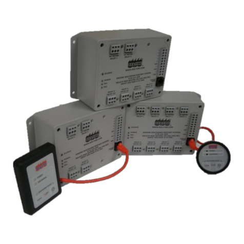
Component overview, the Scanreco G2 radio remote control system
The Scanreco G2 radio remote control system is connected to the RCL 5300 controller and they
communicate with each other in an integrated CAN bus system.
1. Remote control box, MAXI and MINI
2. Radio controller
3. Battery charger
4. Battery, NiMH 7.2 volt
5. Remote control cable, 10 m
7. Cable kit with cables for the power supply and digital outputs
8. Cable kit with analogue/digital outputs
9. External antenna (option)
9

Scanreco G2 radio remote control system
5
HMF Technical Service Department
Rev.: 20-13
Remote control box, MAXI or MINI
The Scanreco G2 radio remote control system includes two versions of remote control boxes -
MAXI or MINI. Their functionality is the same apart from the fact that the MINI version only has up
to 6 linear control levers because of its size.
The remote control boxes can be configured with different control lever combinations in both EU
and NAFTA frequency versions.
Compared to the previous G1 system, it is now possible to configure the MAXI remote control box
(option) with an additional 3 tumbler switches (4, 5 and 9).
It is possible to configure both types of remote control boxes with a display.
Control lever
Configuration
MAXI-linear
1 - 8
MAXI-
joystick
2-0-2, 2-2-2, 2-3-2
3-2-3, 3-0-3
MINI-linear
1 - 6
MINI-joystick
2-0-2, 2-2-2
Operation, indications and display indications etc. are stated in the Scanreco G2 Instruction
Manual.

Scanreco G2 radio remote control system
6
HMF Technical Service Department
Rev.: 20-13
New functions in the HMF InfoCentre
The InfoCentre of the remote control box has the following indications and operation:
- A big display with a detailed graphic screen.
- The display has a status bar that illustrates the same as the percentage indication.
- The RUN, FUNC, 90 %, 100 % and Slewing symbol diodes.
- The + and ÷ press buttons for adjusting the sound level of the buzzer.
- The ↑/↓ press buttons for scrolling between the different screens.
- The 1-4 press buttons for selecting specific screens.
The screens are configured as described in the Scanreco G2 Instruction Manual.

Scanreco G2 radio remote control system
7
HMF Technical Service Department
Rev.: 20-13
Radio controller
The design of the radio controller:
1. Standard antenna (possibility for connecting external antenna)
2. Tumbler switch, Manual-OFF-Remote
3. M12 plug for remote control cable
4. LED status indication of the functional condition
5. LED display, 2 x 7 segment
•Plastic box with protection class IP65.
•All electric in- and outputs are protected against polarity reversal, over current and EMC/FR.
•Power supply: 12/24 V direct current (+/- 20 %, max. ripple 5 %).
•Built-in radio receiver.
•Tumbler switch:
In Remote position, the crane is
controlled from the remote control box.
In Manual position, the crane is
manually controlled by means of the
control valve levers.
In OFF position, the radio controller is
completely interrupted.
•All electronics are cast.
•Built-in 10 ampere positive fuse.
•All electric in- and outputs are
connected via plug and socket-outlets.
•The cable lead-ins at the bottom can
be dismounted.
•Different cable kits are used depending
on the system configuration.

Scanreco G2 radio remote control system
8
HMF Technical Service Department
Rev.: 20-13
General system description
The radio controller is connected to the RCL 5300 controller, which is the master controller in a
CAN bus network where the radio remote control system and the safety system of the crane are
communicating in an integrated system.
Depending on the system configuration, the radio controller can control different combinations of
crane and stabilizer functions as well as digital functions.
CAN proportional control of PVED electric activations
The CAN output in the radio controller is via the RCL 5300 controller connected to the PVED
electric activations of the Danfoss PVG 32 control valve, which are activating the individual crane
functions proportionally with the signal from the remote control levers.
Proportional voltage control of the PVE electric activations
The output terminals in the radio controller are via cables directly connected to the PVE electric
activations of the Danfoss PVG 32 control valve, which are activating the individual crane functions
proportionally with the signal from the remote control levers.
In 24 volt systems the proportional voltage control is adjusting according to the following values
6 ⇐12 ⇒18 volt. In 12 volt systems the voltage control is 3 ⇐6 ⇒9 volt.
Please note: The above control requires a radio controller with another type of hardware.
Proportional current control of the PWM electric activations
The digital outputs in the radio controller are via cables directly connected to the PWM (Pulse
Width Modulation) electric activations of the control valve, which are activating the individual crane
functions proportionally with the signal from the remote control levers.
All in all it is possible to connect 8 dual (A and B direction) PWM outputs.
Digital voltage control of ON-OFF solenoid valves (RC-controlled stabilizers)
The digital outputs in the radio controller are via cables directly connected to the solenoid valves of
the stabilizer control valve, which are activating the different stabilizer functions ON-OFF with the
signal from the control levers of the remote control box.
Combined radio remote control functions
The above-mentioned radio remote controls may be combined. Typically the CAN proportional
control of the Danfoss PVED electric activations is combined with the voltage control of the ON-
OFF solenoid valves on the stabilizer control valve.
Digital functions
The radio controller has 14 digital outputs for for example engine functions, horn, light tower as
well as other available functions.

Scanreco G2 radio remote control system
9
HMF Technical Service Department
Rev.: 20-13
Set-up guides
Installation of the radio controller
•To ensure optimal radio communication the radio controller must be fitted in as high a place as
possible and with as much space around it as possible. If the antenna is surrounded by fixed
objects, this will weaken the radio reception. It may be necessary to connect an external
antenna.
•The antenna must not touch metallic parts.
•The radio controller must be fitted on a bracket free of vibrations and must be at a distance
from heat coming from for example the exhaust system of the engine.
•The electric cables must turn downwards and away from the radio controller.
•Grease the internal plug connections with water repellent grease meant for electronic
components.

Scanreco G2 radio remote control system
10
HMF Technical Service Department
Rev.: 20-13
•Penetrate the membranes of the cable lead-ins with for instance a small screwdriver. The fitting
must be tight when pulling through the cable to ensure a tight system.
•Fit a cable relief on the inside.
•Cover all visible metallic parts on wires and in ground connections with water repellent lubricant.
•Position the cables as shown in the picture.
In case of welding on the vehicle
Before carrying out any welding on the vehicle, all electric connections for external components
and power supply (both + and -) must be dismounted.
In case of recharging by means of a boost starter
Remove the cable for the power supply, if the battery of the vehicle is discharged, and
connect a “boost starter” to start the engine. Any kind of too high charging voltage (power
supply) or voltage peaks entail the risk of overloading and in the worst case damaging the
electronic safety system.

Scanreco G2 radio remote control system
11
HMF Technical Service Department
Rev.: 20-13
Plug and socket outlets in the radio controller
Each of the 6 plug and socket-outlets are dedicated to different crane and extra functions, CAN bus
and power supply.
In certain applications the outputs may be configured for alternative functions.
In the table you can see the interconnection between sockets, functions and output cables.
Sock
et
Function
Cable
K1
Outputs for proportionally controlled PWM (Pulse Width
Modulation) electric activations or
outputs for digitally controlled ON-
OFF solenoid valves on
the stabilizer control valve
1A-4A and 1B-4B
K3
Outputs for proportionally controlled PWM electric
activations
or
outputs for digitally controlled ON-
OFF solenoid valves on
the stabilizer control valve
5A-6A and 5B-6B
K4
Outputs for engine control functions and horn
EX1 and 60 (horn)
K6
Outputs for digital control of available ON-OFF solenoid
valve functions
EX2
K7
Power supply (+/-) and dump output (wire security signal
for RCL 5300)
RC
K8
CAN-in from RCL 5300
Possibility for CAN-
out for a subsequent CAN controller, if
any.
EX3

Scanreco G2 radio remote control system
12
HMF Technical Service Department
Rev.: 20-13
Survey of terminals in the radio controller
In the below table we have stated the number of the output terminals and output cables as well as
the signal.
Connection of output cables and the corresponding function can be found in the electric diagrams
for the Scanreco G2 radio remote control system.
Please note: In certain applications the output terminals may be configured for alternative
functions.
Terminals in
K1 socket
Cable
Signal
Terminals
in K3
socket
Cable
Signal
Terminals
in K4
socket
Cable
Signal
K1.1
1A
PWM +
K3.1
5A
PWM +
K4.1
EX1
ON-OFF 1
K1.2
1A
PWM ÷
K3.2
5A
PWM ÷
K4.2
EX1
ON-OFF 2
K1.3
1B
PWM +
K3.3
5B
PWM +
K4.3
EX1
ON-OFF 3
K1.4
1B
PWM ÷
K3.4
5B
PWM ÷
K4.4
EX1
ON-OFF 4
K1.5
2A
PWM +
K3.5
6A
PWM +
K4.5
EX1
ON-OFF 5
K1.6
2A
PWM ÷
K3.6
6A
PWM ÷
K4.6
EX1
ON-OFF 6
K1.7
2B
PWM +
K3.7
6B
PWM +
K4.7
EX1
GND (÷)
K1.8
2B
PWM ÷
K3.8
6B
PWM ÷
K4.8
EX1
DIG IN 1
K1.9
3A
PWM +
K3.9
7A
PWM +
K4.9
EX1
DIG IN 2
K1.10
3A
PWM ÷
K3.10
7A
PWM ÷
K4.10
EX1
DIG IN 3
K1.11
3B
PWM +
K3.11
7B
PWM +
K4.11
EX1
Input, VDC
K1.12
3B
PWM ÷
K3.12
7B
PWM ÷
K1.13
4A
PWM +
K3.13
8A
PWM +
K1.14
4A
PWM ÷
K3.14
8A
PWM ÷
K1.15
4B
PWM +
K3.15
8B
PWM +
K1.16
4B
PWM ÷
K3.16
8B
PWM ÷
Terminals in
K6 socket
Cable
Signal
Terminals
in K7
socket
Cable
Signal
Terminals in
K7 socket
Cable
Signal
K6.1
EX2
ON-OFF 7
K7.1
RC
12/24 V
K8.1
EX3
CAN High
K6.2
EX2
ON-OFF 8
K7.2
RC
GND (÷)
K8.2
EX3
CAN Low
K6.3
EX2
ON-OFF 9
K7.3
RC
Wire security
K8.3
EX3
CAN ÷
K6.4
EX2
ON-OFF 10
K7.4
RC
DMP ÷
K8.4
EX3
CAN High
K6.5
EX2
GND (÷)
K8.5
EX3
CAN Low
K6.6
EX2
ON-OFF 11
K6.7
EX2
ON-OFF 12
K7.8
EX2
ON-OFF 13
K8.9
EX2
ON-OFF 14
K9.10
EX2
GND (÷)

Scanreco G2 radio remote control system
13
HMF Technical Service Department
Rev.: 20-13
The Scanreco G2 radio remote control system and CGW 5355
In the service terminal CGW5355 a number of functions, used for setting-up, downloading,
monitoring and reading of error log in relation to the G2 radio remote control system, have been
implemented.
Most of the SG2 set-up is carried out in the PWM Mixer feature as indicated in Fig. 7.
Survey of CGW 5355 functions
•Profile > View > Setup > Features > PWM Mixer
oDigital: K4.1-6 and K6.9
oPWM:
PWM Max Current
PWM Start Kick
PWM Frequency
PWM Dither Freq
Source: PWM 1A, K1.1 – PWM 8B, K3.15
Source Setup: A/B Proportional, A/B Digital and A/B Digital, hold
Min. Current: 0-100 %
Max. Current: 0-100%
Ignore Dump
•Network > CAN-Modules > Network: 100 Scanreco G2
•Monitor > Output signals > Remote: Button 1-28
•Black box
oError 1-50
Timestamp: date and time stamp
Emergency error: CAN error code
Manufacturer error: SG2 error code
RCL error: Error code indicated on the RCL display
•Tools:
o<Download Icons>
o<Download Texts>
Fig. 7
PWM Mixer ...25.1
Digital
PWM
Digital
Digital ...1.1
K4.1 ENGINE FULL
K4.2 ENGINE START
K4.3 ENGINE STOP
K4.4 ENGINE RPM P
...
K6.9 None
K4.1 ENGINE FULL
PWM ...2.1
PWM Max Current 1000mA
PWM Start Kick 10%
PWM Frequency 200Hz
PWM Dither Freq 70Hz
Source
...
Source
Features ...1.25
Display
Regeneration
Stabilizer con
Remote control
Stab safety sys
PWM Mixer
PWM Mixer
Source ...5.2
PWM 1A, K1.1 Slew
PWM 1B, K1.3 Slew
PWM 2A, K1.5 Boom
PWM 2B, K1.7 Boom
PWM 3A, K1.9 Jib
PWM 3B, K1.11 Jib
PWM 1A, K1.1 Slew

Scanreco G2 radio remote control system
14
HMF Technical Service Department
Rev.: 20-13
Description of Scanreco G2 parameters in the CGW 5355
In the table below is indicated the PWM Mixer parameters in the CGW 5355, the corresponding
menu items and description of functions and parameters.
Please also see examples of setting up operation of crane, stabilizer and extra functions from the
remote control box in this manual.
PWM Mixer ...25.1
Digital
PWM
Digital
Digital ...1.1
K4.1 ENGINE FULL
K4.2 ENGINE START
K4.3 ENGINE STOP
K4.4 ENGINE RPM P
...
K6.9 None
K4.1 ENGINE FULL
PWM ...2.1
PWM Max Current 1000mA
PWM Start Kick 10%
PWM Frequency 200Hz
PWM Dither Freq 70Hz
Source
...
Source
Features ...1.25
Display
Regeneration
Stabilizer con
Remote control
Stab safety sys
PWM Mixer
PWM Mixer
Source ...5.2
PWM 1A, K1.1 Slew
PWM 1B, K1.3 Slew
PWM 2A, K1.5 Boom
PWM 2B, K1.7 Boom
PWM 3A, K1.9 Jib
PWM 3B, K1.11 Jib
PWM 1A, K1.1 Slew
Menu item in CGW
5355
Description of functions and parameters
1.1.1.1.1.25
PWM Mixer
The main function which is to be used when the PWM outputs in the Scanreco G2
radio remote control system are to be set up.
1.1.1.1.1.25.1
Digital
It is possible to set up 14 digital signals from the K4 and K6 sockets. The K4
outputs are used as standard for engine control signals, and the K6 outputs are
used for extra optional functions.
1.1.1.1.1.25.2
PWM
It is possible to set up 8 dual outputs (direction A and B) from the K1 and K3
sockets.
The outputs can be set up in order to control PWM signals from the remote control
levers (e.g. proportional control of crane functions) or digital signals (extra optional
functions).
1.1.1.1.1.25.2.1
PWM Max Current
In this menu item is inserted a value for the current intensity (mA) depending on
whether the system voltage is 24 or 12 volt.
The standard value for 24 volt NEM solenoid valves is 650 mA.
The standard value for 12 volt NEM solenoid valves is 1400 mA.
1.1.1.1.1.25.2.2
Start Kick
The function adds extra starting current to ensure a stable starting up of activation
of the valve, as there is stick-slip in the seals etc., when the spool has been in
neutral position for a while.
The standard value is 20 % for the NEM control.
1.1.1.1.1.25.2.3
PWM Frequency
The PWM (Pulse Width Modulation) carrier frequency (Hz) states the number of
digital pulses that are controlled with.
The standard value is 200 Hz (pulses per second) for the NEM control.
1.1.1.1.1.25.2.4
PWM Dither Freq
The PWM Dither frequency (Hz) is a superposed carrier frequency, which ensures
that the solenoid valve and thereby the spool is kept in constant movement to
prevent stick-slip and give a better regulation.
The standard value is 70 Hz for the NEM control.

Scanreco G2 radio remote control system
15
HMF Technical Service Department
Rev.: 20-13
Menu item in CGW
5355
Description of functions and parameters
1.1.1.1.1.25.2.5
Source
Each PWM output can be controlled by an optional output signal - operated from the remote
control box - in the Source menu. The output signal may be for a crane function, stabilizer
function or extra function.
The following outputs can be activated:
1.1.1.1.1.25.2.5-
PWM 1A, K1.1 - PWM 4A, K1.13 and
1.1.1.1.1.25.2.5-
PWM 5A, K3.1 - PWM 8A, K3.13
1.1.1.1.1.25.2.5-
PWM 1B, K1.3 - PWM 4B, K1.15 and
1.1.1.1.1.25.2.5-
PWM 5B, K3.3 - PWM 8B, K3.15
1.1.1.1.1.25.2.6
Source Setup
In Source Setup it is possible for each PWM output signal in Source to select (SET
and arrow down) between the following signal types:
1. None
2. A Prop.
Operation from a remote control lever.
A proportional signal for a NEM activation for oil flow to the A port on a crane
control valve function (a crane function selected in Source) or the A port of
another type of proportional control valve (an Ex. 1-16* function selected in
Source).
3. B Prop.
Operation from a remote control lever.
A proportional signal for a NEM activation for oil flow to the B port on a crane
control valve function (a crane function selected in Source) or the B port of
another type of proportional control valve (an Ex. 1-16* function selected in
Source).
4. A Dig.
Operation from a remote control lever.
A digital signal for an ON-OFF activation for oil flow to the A port on a stabilizer
control valve function (an STB 1-16 function selected in Source) or another type
of ON-OFF control valve (an Ex. 1-16* function selected in Source).
5. B Dig.
Operation from a remote control lever.
A digital signal for an ON-OFF activation for oil flow to the B port on a stabilizer
control valve function (an STB 1-16 function selected in Source) or another type
of ON-OFF control valve (an Ex. 1-16* function selected in Source).
6. A Hold
Operation from a remote control lever.
A digital holding signal for an ON-OFF activation for oil flow to the A port on a
control valve function, which is to be kept activated (an Ex. 1-16* function
selected in Source).
7. B Hold
Operation from a remote control lever.
A digital holding signal for an ON-OFF activation for oil flow to the B port on a
control valve function, which is to be kept activated (an Ex. 1-16* function
selected in Source).
8. Digital
Operation from a tumbler switch or push button on the remote control box.
An ordinary digital output signal for a function selected in Source.
9. Digital hold
Operation from a tumbler switch or push button on the remote control box.
An ordinary digital holding signal for a function selected in Source.
*) The Ex. 1-16 signals can be used for control of the control valves for optional
extras. They can be used both in crane mode (e.g. Ex. 1-4) and stabilizer mode (for
example Ex. 8-16). However, the same Ex.-signal cannot be used both in crane
mode and stabilizer mode.
The signals are by default proportional and come from an activation of the remote
control levers on the remote control box.
The signals can also be digital (or digital with holding function) so that the remote
control levers can be used "as push buttons" or "tumbler switches" for activating
and deactivating an output terminal.

Scanreco G2 radio remote control system
16
HMF Technical Service Department
Rev.: 20-13
Menu item in CGW
5355
Description of functions and parameters
1.1.1.1.1.25.2.7
Min. Current
Indicates the minimum current in % of PWM Max Current for a solenoid valve. The
value is individually adjustable for each single PWM output so that the manual
control valve lever starts activation (flow from the port) when the remote control
lever in case of activation has just passed the dead band.
If a PWM output is used for ON/OFF control of a solenoid valve, the value is
adjusted at 0 %.
1.1.1.1.1.25.2.8
Max. Current
Indicates the maximum current in % of PWM Max Current for a solenoid valve. The
value is individually adjustable for each single PWM output so that the manual
control valve lever is just completely activated when the remote control lever in
case of activation is completely activated.
If a PWM output is used for ON/OFF control of a solenoid valve, the value is
adjusted at 100 %.
1.1.1.1.1.25.2.9
Ignore Dump
With the parameter Ignore Dump it is possible to select whether the current output
is to be deactivated when the dump valve is open (no dump signal).
Ignore Dump selected (ticked off) ⇒The current output is not deactivated in case of
dump.
Ignore Dump not selected (not ticked off) ⇒The current output is deactivated in
case of dump.
For example the work light (LIGHT) or functions used in stabilizer mode are not to
be turned off in case of dump.

Scanreco G2 radio remote control system
17
HMF Technical Service Department
Rev.: 20-13
Setting up of output signals by means of the CGW 5355
By means of the CGW 5355 it is possible to select signal sources which activate different output
signals from the Scanreco G2 radio controller or controllers in the RCL 5300 Safety System.
In the table below is indicated each single selectable signal name, the corresponding signal
source and a description of the functionality controlled by the signal.
Please note that it is the same set of parameters of signal names that can be selected in the
Output config, menu 1.1.1.1.2.4 when setting up the output terminals in the RCL 5300 and other
controllers in the CAN network. Therefore there will also appear signal names others than the
ones relating to the Scanreco G2 radio remote control system.
The signal names are indicated in the order in which they appear in the CGW display when
pressing SET on an output in PWM Mixer - PWM - Source, menu item 1.1.1.1.1.25.2.5.1-16 and
when pushing the "arrow down" button.
In the table is indicated signal sources from
the remote control levers, tumbler switches
and push buttons on the remote control
box.
Designations of tumbler switches and push
buttons appear from the photo.
Signal name
Signal source
Description of signal
None
No
No signal
OFF
No
Always low signal
ON
Signal from controllers in the RCL
5300 safety system or from the
Scanreco G2 radio controller.
Constant high signal
DMP1
Signal from the RCL 5300
controller.
High signal for dump valve 1 in all
situations where the RCL safety system
allows the crane to work.
DMP2
Signal from the RCL 5300
controller.
High signal for dump valve 2 in all
situations where the RCL safety system
allows the crane to work.
STB SHIFT VALVE
2 x activating the yellow push
button (pos. 7) on the remote
control box or the RCL 5300
indicator panel.
High signal for the change-over valve - oil
flow for crane functions or stabilizer
functions. Change from crane mode to
stabilizer mode.
HDL
Signal from the RCL 5300 safety
system when the load moment of
the crane is less than 90%.
High signal for the HDL valve when the
crane is in crane mode - not HDL.
REGEN BOOM
Activation of the ON push button on
the remote control box.
High signal for the regeneration valve on
the "boom up" function (regeneration),
when the load moment of the crane is less
than 50 %.

Scanreco G2 radio remote control system
18
HMF Technical Service Department
Rev.: 20-13
Signal name
Signal source
Description of signal
REGEN JIB
Activation of the ON push button on the
remote control box.
High signal for the regeneration valve on the "jib
- up" function (regeneration), when the load
moment of the crane is less than 50 %.
REGEN EXT
Activation of the ON push button on the
remote control box.
High signal for the regeneration valve on the
"extension - out" function (regeneration), when
the load moment of the crane is less than 50 %.
REGEN BOOM JIB
Activation of the ON push button on the
remote control box.
High signal for the regeneration valve on the
"boom - up" and "jib - up" function
(regeneration), when the load moment of the
crane is less than 50 %.
ENGINE FULL
Activation of tumbler switch no. 1 - to
the left - on the remote control box.
---------------------------------------
Activation of tumbler switch no. 1 - to
the right - on the remote control box.
High signal for the engine control of the truck. In
case of activation, the number of revolutions is
increased to a predetermined value.
Requires selection of Engine in Features.
--------------------------------------------------
High signal for the engine control of the truck,
when a crane function is activated by the remote
control lever.
When the remote control lever is in neutral
position, the signal goes low after a certain
interval: Engine timeout (1.1.1.1.1.9.6).
Requires selection of Engine in Features.
ENGINE RPM M
Activation of tumbler switch no. 3 - to
the right - on the remote control box.
High signal for the engine control of the truck.
The number of revolutions is reduced stepwise
by each activation of the tumbler switch.
ENGINE RPM P
Activation of tumbler switch no. 3 - to
the left - on the remote control box.
High signal for the engine control of the truck.
The number of revolutions is increased stepwise
by each activation of the tumbler switch.
LIGHT
Activated by green press button
(holding) on the RCL 5300 or green
press button on the remote control box.
Signal for a relay that powers a spotlight. The
signal is permanently coded in the RCL 5300
application program.
PVSK DMP
2 x activating the yellow push button
(pos. 7) on the remote control box or
the RCL 5300 indicator panel.
High signal for the PVEO electric activation on
the PVSK module of the Danfoss PVG 32
control valve - change to crane mode - by the
first activation of a crane function with a remote
control lever, when the RCL safety system
allows the crane to work.
PVSK SHIFT
2 x activating the yellow push button
(pos. 7) on the remote control box or
the RCL 5300 indicator panel.
High signal for the PVEO electric activation on
the PVSK module of the Danfoss PVG 32
control valve that changes to stabilizer mode.
HORN
Activation of the ON push button on the
remote control box or the OPT press
button on the RCL 5300 (kept down).
High signal for a horn fitted on the crane.
FLASH
Activation of the green press button
(pos. 6) when starting up the RCL
system.
High signal for the alarm flash. E.g. for LED
band on the stabilizer legs.
ENGINE START
Activation of tumbler switch no. 2 - to
the left - on the remote control box.
High signal for the engine control of the truck.
Starting up the engine.
ENGINE STOP
Activation of tumbler switch no. 2 - to
the right - on the remote control box.
High signal for the engine control of the truck.
Stop of the engine.
EVS BYPASS
Activation of the key switch from the
"EVS on" position to the "2 ZONE LMB
on" position.
High signal when the key switch is in the "2
ZONE LMB on" position. In this position you
change from the EVS system to the 2-stage
LMB system.

Scanreco G2 radio remote control system
19
HMF Technical Service Department
Rev.: 20-13
Signal name
Signal source
Description of signal
WINCH PARK
Activation of the yellow push button
on the remote control box.
High signal for changeover of a solenoid
valve in the hydraulic system for winch, so
that the winch can be moved up into and
down from stowing position.
FJ EX 1
Simultaneous activation of tumbler
switch no. 10 and tumbler switch no.
3 to the left.
High signal for the solenoid valve for
change between Fly-Jib and grab, when
the lever configuration "Fly Jib Shift Grab"
is activated in "Lever Config.".
FJ EX 2
Simultaneous activation of tumbler
switch no. 10 and tumbler switch no.
3 to the right.
High signal for the solenoid valve for
change between Fly-Jib and rotator, when
the lever configuration "Fly Jib Shift
Rotator" is activated in "Lever Config.".
STB LOW
Signal by 0-50 % activation of a
remote control lever in stabilizer
mode.
High signal for the solenoid valve for low
stabilizer speed (1st version of Odin and
Thor stabilizer valve block).
STB HIGH
Signal by 50-100 % activation of a
remote control lever in stabilizer
mode.
High signal for the solenoid valve for high
stabilizer speed (1st version of Odin and
Thor stabilizer valve block).
STB DIR A
Signal by activation of a remote
control lever forwards - in stabilizer
mode.
High signal for the directional valve of the
stabilizer control valve for control of oil flow
for "stabilizer legs - up" and "stabilizer
beams - retract".
STB DIR B
Signal by activation of a remote
control lever backwards - in stabilizer
mode.
High signal for the directional valve of the
stabilizer control valve for control of oil flow
for "stabilizer legs - down" and "stabilizer
beams - extend".
STB 1 - STB 16
Digital signal by activation of a
remote control lever - in stabilizer
mode.
The digital signals control the functions of
the stabilizer control valve (PWM
activations or ON-OFF activations) for
cylinders for stabilizer legs and stabilizer
beams.
Ex.1 - Ex.16
Proportional signal (can be defined
as digital or digital hold) by activation
of a remote control lever - both in
crane mode and stabilizer mode.
The proportional signals (PWM activations)
can operate the control valve functions for
optional extras on the crane or on a
vehicle.
LEV COL 1-12
=
Lever setup 1 - 12
(1.1.1.1.2.8.1-12)
Activation of a tumbler switch or a
combination of tumbler switches.
When activating the tumbler switch, a
signal appears for changeover to another
configuration of the remote control levers. If
for example the crane has radio remote
control of stabilizers, the remote control
levers change function from operation of
crane functions to operation of stabilizer
functions when pushing the yellow press
button twice (2 x yellow) (change between
crane mode and stabilizer mode). By
means of configuration/activation of
different tumbler switches it is possible to
change between up to 12 different types of
operation from the remote control levers.
Led Run
The same signal as for the RUN
diode on the RCL 5300 indicator
panel.
The signal follows the RUN diode: constant
signal or periodic signal.
Led 100
The same signal as for the 100 %
diode on the RCL 5300 indicator
panel.
The signal follows the 100 % diode:
constant signal or periodic signal.
Led 90
The same signal as for the 90 %
diode on the RCL 5300 indicator
panel.
The signal follows the 90 % diode: constant
signal or periodic signal.

Scanreco G2 radio remote control system
20
HMF Technical Service Department
Rev.: 20-13
Signal name
Signal source
Description of signal
RC But 1 (RED)
Activation of the red push button
(pos. 8).
The signal gives the corresponding
functions as when pushing the red press
button on the RCL 5300.
RC But 2 (YELLOW)
Activation of the yellow push button
(pos. 7).
The signal gives the corresponding
functions as when pushing the yellow press
button on the RCL 5300.
RC But 3 (GREEN)
Activation of the green push button
(pos. 6).
The signal gives the corresponding
functions as when pushing the green press
button on the RCL 5300.
RC But 4 (E START)
Activation of tumbler switch no. 2 -
to the left.
In the default settings the signal is used for
starting the engine.
RC But 5 (E STOP)
Activation of tumbler switch no. 2 -
to the right.
In the default settings the signal is used for
stopping the engine.
RC But 6 (RPM P)
Activation of tumbler switch no. 3 -
to the left.
In the default settings the signal is used for
increasing the number of engine
revolutions.
RC But 7 (RPM M)
Activation of tumbler switch no. 3 -
to the right.
In the default settings the signal is used for
reducing the number of engine revolutions.
RC But 8 (FULL)
Activation of tumbler switch no. 1 -
to the left.
High signal for the engine control of the
truck. In case of activation, the number of
revolutions is increased to a predetermined
value.
Configuration N/A.
RC But 9 (AUTO)
Activation of tumbler switch no. 1 -
to the right - on the remote control
box.
High signal for the engine control of the
truck, when a crane function is activated by
the remote control lever.
When the remote control lever is in neutral
position, the signal goes low without delay.
Configuration N/A.
RC But 10 (FLYSH1)
Activation of tumbler switch no. 10
and tumbler switch no. 3 - to the
left.
If there are only 6 remote control levers on
the remote control box and a change-over
valve has been fitted between the Fly-Jib
functions and the extra functions: When
activating the two tumbler switches, the
change-over valve receives a high signal.
Now the remote control lever changes
function from "Fly-Jib - jib" to "rotator".
RC But 11 (FLYSH2)
Activation of tumbler switch no. 10
and tumbler switch no. 3 - to the
right.
If there are only 6 remote control levers on
the remote control box and a change-over
valve has been fitted between the Fly-Jib
functions and the extra functions: When
activating the two tumbler switches, the
change-over valve receives a high signal.
Now the remote control lever changes
function from "Fly-Jib - extension" to "grab".
RC But 12 (OPT 1)
Activation of tumbler switch no. 10
to the right (holding function) or the
left (spring-loaded).
In the default settings the signal is used for
different functions.
Can be used for output signal for optional
extras or as reverser function together with
alternative operation.
RC But 13 (OPT 2)
Like OPT 1.
Like OPT 1.
RC But 14 (OPT 3)
Activation of tumbler switch MICRO
- to the left.
In the default settings the signal is used for
reducing (in steps per activation) the crane
speed.
RC But 15 (OPT 4)
Activation of tumbler switch MICRO
- to the right.
In the default settings the signal is used for
increasing (in steps per activation) the
crane speed after a previous reduction.
Table of contents
