Hogtunes WILD BOAR AUDIO WBA ULTRA KIT RG User manual

WBA ultRA Kit RG
INSTALLATION MANUAL
IMPORTANT!
A Radio “Re-Flash” May be Required.
Please Read Manual For More Information

Wild Boar Audio Contact Information
Tel: 705-719-6361
Thank you for your purchase of Wild Boar Audio’s WBA Ultra Kit RG for
2015+ Road Glide Ultras. We want your new kit to work as well as it was
designed to, so if you have any questions or concerns, please email:
(EST). If you still need help, please consider a professional installation by
your dealer.
IMPORTANT RADIO REFLASH INFORMATION:
From a sonic point of view, Road Glide Ultra has the correct flash,
however, the factory flash in Road Glide Ultra makes the radio play
considerably QUIETER than it could. Less signal out from the radio means
less signal going into the amps. If you install this system without a reflash,
it will sound great, but will NOT reach its potential volume. A radio reflash
by a Techno Research dealer is required to make this system play to its full
volume potential. An OEM Dealer reflash will not “fix” this, as the OEM flash
looks at the bikes VIN and will re-install the same “quiet” flash. To find a
Techno Research dealer near you, please visit:
http://technoresearch.com/index.php/tuning-centers or CALL US!
This manual is written in 4 sections:
Section 1: Front Speaker Installation
Section 2: Rear Speaker Installation
Section 3: Amplifier Installation
Section 4: Final System Adjustments
Please read the notes on the next page
before proceeding with the installation

1
The amp in this kit (WBA 600.4) is rated to produce 150 watts x 4 using the
supplied 4 ohm Wild Boar speakers. The WBA 600.4 should be used with 4 Ω
(ohm) speakers only!
The amplifier has built in protection and will turn itself off if your charging system/
battery goes below 10.5 volts.
In very high heat situations, the 600.4 will shut itself off before it damages itself.
Once cooled down to safe operating temperatures, it will turn itself back on.
This manual is written as if your bike has had no previous amplifiers installed.
BEFORE GETTING STARTED
The WBA 600.4 amplifier is a Class D design. It should be
understood that ALL Class D amplifiers, REGARDLESS OF BRAND, cause
a reduction in FM reception. The WBA 600.4 features a proprietary
circuit design called R.E.M.I.T. (Reduced Electro Magnetic Interference
Technology) that Wild Boar Audio believes gives the BEST FM reception
available for any Class D Amplifier designed for a motorcycle.
If you add additional amplifiers to your system, reduction
of FM reception is increased and is considered normal.
Wild Boar Audio understands that some riders prefer the cosmetics of
in fairing antennas, however it should be noted that NOTHING
works as well as the factory antenna. If FM is an important part of
your riding experience, we strongly advise against the use of
any in fairing type antenna!
Remove the bike’s seat, and undo the main (+ and -) connectors from the battery.
Remove the outer fairing/headlamp assembly and set aside. Refer to a service
manual if you need help with this. NOTE: Placing a towel on the front fender can
help prevent scratches or “dings” from dropped tools or fasteners, etc.
GETTING STARTED

2
Step #1: Grill Trim Ring Selection:
In the box, you will see that the metal mesh grill with tweeter in it is
sitting in the black trim ring. If you turn this over, you will see “tabs” in
the metal mesh used to secure the mesh to the black trim ring have not
been folded over. These were left unfolded in case you want to remove
the mesh, and have your black trim rings customized, or if you want to
place the metal mesh in the chrome trim rings that also came in the box.
No matter which trim rings you choose, the metal mesh grill with tweeter
must be properly “seated” in the trim ring and all 6 metal mesh “tabs”
must be folded over before proceeding.
Step #2: Removing the Factory Grills:
Each factory grill will be removed from the inner fairing by prying up
on them. Start with your fingers, but if you must use a tool, please use
something with a 90° end being extra careful not to scratch your inner
fairing...especially if it’s painted! On the back of each grill, there is a
rubber gasket and 2 white clips which will be removed from the factory
grills and re-installed on the Wild Boar Audio grills.
Step #4: Removing the Factory Speakers:
With the grills off the bike remove the 4 screws that secure the factory
speaker to bike. Gently pull up each factory speaker so it’s coming
away from the bike and carefully remove the speaker wires. Put the
factory speakers aside.
Step #5: Installing the Wild Boar Audio WBC 1654 RG Speaker:
Take a Wild Boar Audio woofer and attach the factory speaker
wires noting they will only go on one way. The #1 reason for tech
related calls is loose wires at the speaker which is why we designed
the self-locking clips on the speaker frame. You will need to “maneuver”
the new woofer into place so it will go past the grill opening on the
inner fairing, noting it will go in without force. In order to make the
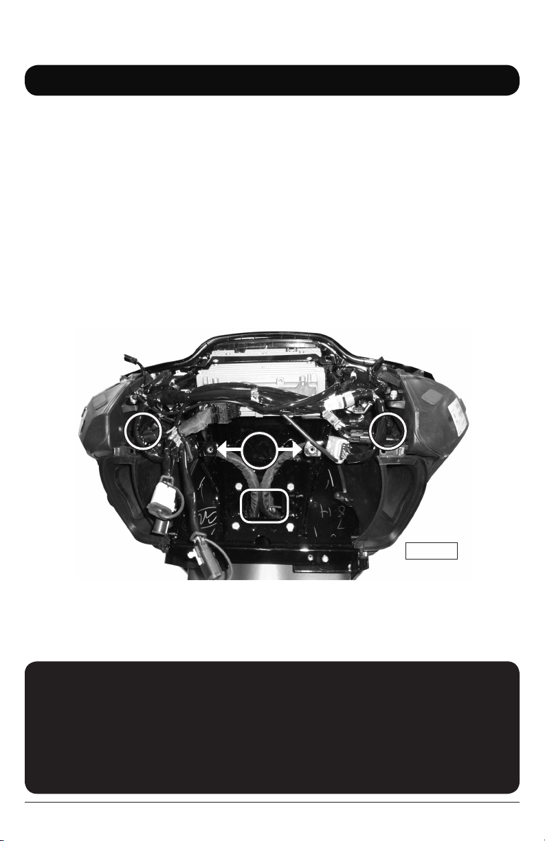
FRONT SPEAKER INSTALLATION
section 1
NOTE: The factory clips must be removed carefully!
Using your thumbnails or a flat edge under each side,
gently pry the 2 ends apart (as per the image) and pull
up to release each clip from the stock grill. If you put a
flat edge under one end only, the clip cannot release
and you have a very good chance of breaking the clip.

3
speaker install properly, the speaker wires must be oriented so they
are closest to the top of the inner fairing (12 o’clock position).
When installed correctly, the 2 small wires that go from the back of
the speaker and “through” the speakers ring will also be in the 12
o’clock position. Reinstall the factory screws to secure the woofers in
place making sure the speaker is flush to the mounting plane of the
factory speaker cabinet.
Step #6: Installing the Wild Boar Audio Speaker Grills:
Before proceeding, please MAKE SURE all 6 metal mesh tabs on the
speaker grills have been folded over to properly secure the grill mesh
to the trim ring! There is a small 2 wire plug for the tweeter on each
grill that will get plugged into the mating connector on the wire coming
through front of the speakers ring. When these are plugged together,
there will be an extra length of wire. In the kit there are foam strips that
are “peel and stick”. You can use the peel and stick foam that came
with the kit to secure the extra length of wire on top of the factory
speaker cabinet. The goal is to make sure this extra length of wire does
not fall in front of the woofer and rattle against the woofer as it’s
playing. With the extra wire out of the way, the new grill will press into
the inner fairing and “click” into its final position.
REAR SPEAKER INSTALLATION
section 2
Step #1: Factory Speaker Removal
Looking at the factory rear speaker, you will see it is secured to the rear
speaker “pod” by 4 T-10 “torx” head screws. Remove these 4 screws.
Lift the speaker out of the rear “pod” and carefully remove each speaker
wire from the speaker. Repeat this for the other side.
Step #2: Installing the New Speakers
Take one rear speaker and carefully attach the factory speaker wires
noting they will only go on one way. In order for the rear speakers to
fit in the factory “pods” they must be aligned correctly. If installing on
the brake side “pod” the speaker connectors must be in the“3 o’clock”
position. On the clutch side, the speaker connectors must be in the “9
o’clock” position. With the speaker in the pod, take one of the plastic
grill trim rings and sit it on the speaker. Using the 4 factory torx screws,
secure the speaker/grill ring to the “pod”. There is no reason to over
tighten these screws! Repeat for the other side of the bike and you are
done!

AMPLIFIER INSTALLATION
section 3
IMPORTANT NOTE BEFORE PROCEEDING
Power wires and wires for rear speakers will travel from inner fairing
area towards the back of the bike. You can run wires in the factory
wire “chase” which is under the fuel tank along the frame, or up
and over fuel tank, but under the chrome console. If you are
comfortable removing and re-installing your bike’s fuel tank, doing
it now can make running the wires much easier.
As the amplifiers come in the box, they are “stuck” to a mounting plate for use in
FLH (Batwing) model bikes. “Peel” the amps off the plate and put that plate aside
as it’s not required for FLTR (Road Glide) installations.
As stated in the “Important Notes” at the beginning of this manual, the required
radio flash is called “4 speaker no amp” and is required for your system to work
properly. The 4 speaker no amp flash is what comes from the factory on all non
CVO model Ultras. Please refer to these important notes or CONTACT US if you
have questions!
The image below will be one you can reference throughout the installation. Please
take a minute and familiarize yourself with the items listed below in the image.
A
B
CD
Figure 1.1
A = Mounting points for Headlight assembly
B = Wire passage from fairing to bike
C = Brake side speaker harness (Pink and Pink with Black Stripe wires)
D = Clutch Side Speaker harness (Pink and Pink with Black Stripe wires)
4

5
Step #1: Locate the “splitter” power harness included in this kit. You will see one
end that has “ring terminals”, and the other end that “splits” and has
2 power connectors on it. Using Fig 1.1 on page 5 for reference, run
the “ring terminal end” of the power harness through “B”. Position it so
the 2 power connectors on the “split end” are accessible in the inner
fairing and the slack can be adjusted later in the installation. Just in front
of the tank, there is a structure that attaches the fairing to the frame of
the bike. The power harness will pass through this structure and exit
through the rectangular opening where the factory harness also exits the
structure on the BRAKE side of the bike. Note: it can be easier to pass
the wire harness through the rectangular opening
if you “open” the fuse holder and remove the fuse
before passing the wire harness. Once the ring
terminal end of the wire harness is through the
rectangular opening and most of the slack is taken
up, move to the next step.
Step #2: Locate the bag labeled “rear”. You will
see this long harness has 2 four pin
plugs on one end, and 2 large multi pin
connectors on the other end. At the area
where the power harness exited the
rectangular opening on the brake side of
the bike, you will need to “fish” the end of
the rear harness with 2 four pin connectors
so they end up in the general area where
the connectors of the power harness are
inside the fairing.
Step #3: Preparing the Plate
for the Ampliers:
Locate the Road Glide Plate
that came in the kit (Fig 1.2).
Locate the 2 “hook and loop”
adhesive pieces included in the
kit and separate the halves of
each. With the plate at room
temperature or higher, apply
one side of the hook and loop
to the front of the plate as
shown by the black rectangle
also is Fig 1.2. Apply a
second piece on the back
of the plate as well.
Fig 1.2
Fig 1.3

6
IMPORTANT
In this install we refer to one amp as the “Master” and the other
amp as the “Slave”. The Master always has the main input
harness go into it, and is always the amp that powers the
front fairing speakers. When installed, the amp on the
BACK SIDE of the plate is the MASTER AMPLIFIER.
Step #4: “Stick” one of the amplifiers to the BACK of the plate in the same
orientation as shown in Fig 1.3.
Step #5: Using Fig 1.1 on page 5 for reference, locate the 4 bolts on each
of the 4 corners around “B” and remove the ones on top left and top
right (only). It’s best to have the amp on the plate near you before
proceeding.
Step #6: Using Fig 1.1 on page 5 for reference, locate “C” and “D” which are
the 2 pin plugs on each front speaker’s cabinet that have pink and pink
with black stripe. These plugs attach the speaker’s wiring to the bike’s
wiring and need to be separated. Locate the “main input” harness and
insert its 8 pin plug into the “audio input” on the MASTER (back side)
amplifier. On this harness, take the plug with the green heat shrink on
the end and install it into the mating plug on the brake side of the bike.
Take the plug with the yellow heat shrink on the end and install it into the
mating plug on the clutch side of the bike.
Step #7: Locate a bag with a harness in it that says “Audio Out” and plug it
into the amplified out “pigtail” on the Master (back) amplifier. Take the
2 pin plug with the blue heat shrink on one end and install it into the
plug going into the brake side speaker cabinet. Take the 2 pin plug
with the brown heat shrink and install it into the plug going into the
clutch side speaker cabinet.
Take one of the 2 power connectors on the splitter harness, and plug it
into the power connector on the Master (back) amplifier.
IMPORTANT — Please make sure the 3 position ABC
switch on the end of each amp is set to “A”.
Since the Road Glide Ultra radio has a fader control,
“B” and “C” are not used for this installation.

7
Step #8: Using Fig 1.1 on page 5 for reference, you will see 2 large factory
harnesses between “A” and “B”. Wiggle the amp/plate into place
around these harnesses so that the holes on the “legs” at the bottom
of the plate line up with the holes where the factory bolts around “B”
were.
With the plate in position, reinstall the factory bolts around “B” which
will secure the Master amp on its plate to the bike.
Step #9: Take the second (Slave) amp and plug the second power connector
from the splitter power into the amp. Locate the harness labeled “input
link”. Take the 8 pin plug on the input link and plug it into the “audio
input” on the “Slave” (front side) amplifier. The black 4 pin plug on
the rear harness will plug into the “amplified output” on the slave (front
side) amplifier. On the input link now plugged into the Slave (front side)
amplifier, there are 2 empty blue 4 pin plugs. The white 4 pin plug on
the rear harness will plug into the mating blue plug on the input link.
The leftover blue plug on this input link may be used later to send music
to additional amplifiers as they become available.
You can now “stick” the Slave (front) amplifier to the plate in the same
orientation as shown in Fig 1.4.
Fig 1.4
Step #10: Attach the amp’s brown wire to the negative (-) battery terminal and the
amp’s red wire to the positive (+) battery terminal. The factory battery
wires are also re-installed at this point. When attaching the power and
ground wires, it is always a good practice to do the negative first.
When the positive connector touches the battery, some sparking is
normal. This is a function of the capacitors in the amplifiers charging up.

8
This section is VITAL to the correct operation
of the system, please make sure you read
and understand it, or contact us!
Step #1: This kit has been designed to give great sound with the radio bass and
treble controls in the middle position. Adjusting the bass and treble up
or down no more than 3 bars from center will give excellent and reliable
performance for most kinds of music. If you choose to exceed this
suggestion and play at high volume levels, you may damage your
system!
Step #2: The Wild Boar Audio 600.4 amplifier is a HIGH POWER amplifier
specifically designed to work on the small charging system of a
motorcycle. DO NOT start your motorcycle with the radio past half
on the volume dial! When the start button is hit, all available current
goes to your bike’s starter which “starves” the amplifier and may cause
damage to your speakers!
FINAL SYSTEM ADJUSTMENT
section 4
Before re-installing outer fairing, turn front wheel
to each extreme side making sure any wiring is
not impeding the steering of the motorcycle.
Failure to do so can result in serious
injury or death!
Re-install the fairing and the system is now ready to enjoy!
Step #11: Turn the stereo on and, at low volume, test to make sure all four
speakers are working.
Step #12 Re-install the seat making sure the amplifier’s “+” and “-” connectors are
positioned in such away so they will not bend or break when the rider’s
weight is on the seat.
This is the best time to take a few minutes to “clean up” the wiring
and secure using supplied zip-ties.

9
Wild Boar Audio branded speakers are warranted for a period of 5 years to
the original purchaser. Wild Boar Audio branded amplifiers are warranted for a
period of 3 years to the original purchaser. Proof of purchase is required for all
warranty claims. Please contact Hogtunes head office for all warranty claims.
Products found to be defective during the warranty period will be repaired or
replaced (with a product deemed to be equivalent) at Hogtunes sole discretion.
Hogtunes/Wild Boar Audio’s complete warranty policy is available on our website
at www.wildboaraudio.com
What Is Not Covered:
1) Any expense related to the removal or re-installation of products.
2) Repairs to these products performed by anyone other than Hogtunes, Inc.
3) Subsequent damage to any other components.
4) Any product purchased from a non-authorized Wild Boar Audio dealer.
5) Damage to products from an accident or collision.
6) Damage from incorrect installation, improper use, abuse or modifications.
7) Reduction of FM reception.
8) Damage caused by incorrect factory radio “re-flash” and amp combination
9) Damage to inbound warranty product due to improper packing.
IMPORTANT: In the event of a warranty claim, please ll
out the form in the Warranty section of our website
www.wildboaraudio.com. Valid claims will have a Return
Authorization Number (RA#) generated which MUST appear
on the outside of the box when it arrives to our oces.
Goods Arriving Without An RA# Will Be Refused!
warranty information
Please record your amplifier’s serial #’s here:
“Master aMp”
“slave aMp”
Wild Boar Audio is owned by PowerSports Audio Inc.

Wild Boar Audio products will play much louder than the
Original Equipment, which can be a distraction to
the rider and/or passenger. Please use caution
when adjusting or playing your stereo
at high volume, especially in trac.
You are a valued customer so please:
Ride Alert
Arrive Alive!
www.wildboaraudio.com
www.hogtunes.com
Version 1.2
Table of contents
Other Hogtunes Car Receiver manuals
Popular Car Receiver manuals by other brands

Aiwa
Aiwa NSX-SZ4 Service manual

Bosch
Bosch Dover USB40/80 Operating and installation instructions

Clarion
Clarion VXZ646 Installation/wire connection guide

Blaupunkt
Blaupunkt HEIDELBERG Heidelberg CD51 operating instructions

Axis Car Audio
Axis Car Audio AX1502BT instruction manual

JVC
JVC KD-SX870 instructions