Hogtunes RETRO 450.4 KIT User manual


Thank you for choosing the Hogtunes Retro 450.4 Kit for 2014+ Rushmore
Platform Street Glides and Road Glides. Since positive word of mouth is the
best way to grow our business, we want your new system to work as well as it
was designed to. If you have any questions or concerns, we are here to help.
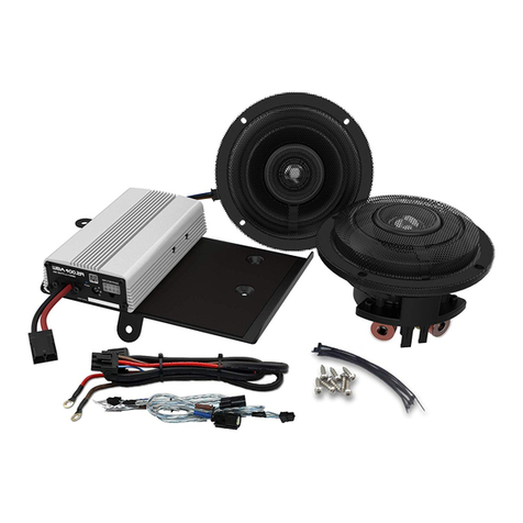
To help protect your bike’s electrical system and battery, the amp has a built
in feature where it will turn itself off if it sees less than 10.5 volts, whether
the bike is running or not. If you’re listening to your stereo while not riding,
this feature can help protect your battery so the bike can still start. If you’re
riding and the amp shuts off, this could be showing a potential issue with your
charging system. If this feature is activated and the amp shuts off, it will turn
the amp back on again if the voltage exceeds the 10.5 volt threshold.
REV 225-RM is rated for 112.5 watts per channel @ 2 ohms. This system will
work fine without a radio reflash, however, if you have the radio reflashed
by an HD dealer, or a Techno Research dealer, the radio fader function will
be activated and you will be able to control volume between the front and lid
speakers from your radio. If you choose to have the re flash done by an HD
Dealer, the flash you need is called “Front and rear speakers without amp”
which is the same factory flash that comes on Ultra Models. Don’t worry about
the fact you’re putting amps in! The flash you want gives us the sound etc from
the radio for the amps being installed. If you go to a Techno Research dealer,
their equipment has a “Wild Boar Audio” flash built in and that is what they
need to use. Installation for Street Glide Models starts on Page 3, and
Installation for Road Glides starts on Page 8. The lid cut in and 6”x9”
installation (common for both model bikes) starts on page 13.
The REV 225-RM amplifier is a Class D design. It should be
understood that ALL Class D amplifiers, REGARDLESS OF BRAND, cause
a reduction in FM reception. The REV 225-RM features a proprietary
circuit design called R.E.M.I.T. (Reduced Electro Magnetic Interference
Technology) that Hogtunes believes gives the BEST FM reception
available for any Class D Amplifier designed for a motorcycle.
If you add a 2nd or 3rd model amplifier to your system, reduction
of FM reception is increased and is considered normal.
Hogtunes understands that some riders prefer the cosmetics
of in-fairing antennas, however it should be noted that
NOTHING WORKS AS WELL AS THE FACTORY ANTENNA.
If FM is an important part of your riding experience, we strongly
advise against the use of any in fairing type antenna!
Hogtunes Contact Information
Email: [email protected]
Telephone (USA) 608-554-7631 • (Canada) 705-719-6361
HOGTUNES 2 INTRODUCTION

STREET GLIDE INSTALLATIONSTREET GLIDE INSTALLATION
HOGTUNES 3 STREET GLIDE INSTRUCTIONS
Step #1: Remove the seat and both wires (+ and -) from the battery. Remove the
outer fairing/headlamp assembly and set aside. Refer to a service
manual if you need help with this. NOTE: Placing a towel on the front
fender can help prevent scratches or “dings” from dropped tools or
fasteners, etc. Expletives will also be kept to a minimum!
Step #2: SPEAKER CABINET REMOVAL: On the brake side speaker cabinet,
carefully remove the cable going into the power port/cigarette lighter
assembly. If your bike has the CB module (mounted “sideways” on the
clutch side cabinet) undo the antenna cable and main harness. The
CB Module will stay attached to the clutch side cabinet when removed.
Undo the speaker wire plugs going into each cabinet (pink & pink with
black stripe wires).
The speaker cabinets are vital to the fairings structure.
DO NOT operate the bike without the speaker cabinets installed!
NOTE: We STRONGLY suggest COMPLETING the speaker swap on one side
and then moving to other side! Figure 1.1 and 1.2 (below) have arrows that point
to the factory fasteners that will be removed to allow the cabinets to come
out of the bike. Although the Brake Side is shown below, fastener locations
are common for both brake and clutch side cabinets.
Figure 1.1
Side view of brake side cabinet
Figure 1.2
Back view of brake side cabinet

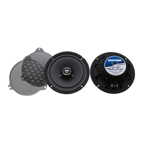
Step #3: INSTALLING THE NEW SPEAKER: With the cabinet removed from
the bike, undo the four screws that hold the factory speaker to the
cabinet. Carefully take off each speaker wire by disconnecting one at
a time. Take a Hogtunes speaker and attach the factory speaker wires,
noting they will only go on one way. You will see a small locator “peg”
on the speaker cabinet. There is a provision on the underside of the
462F-RM that allows the speaker to sit over this, so there is no reason to
cut the peg off. Using the factory screws, attach the new speaker to the
cabinet. Please make sure the speaker is flush to the cabinet when
installed. Bass response will be greatly reduced if the speaker is not
flush to the cabinet! The new speaker can be used behind the factory
cloth covered grill, but the speaker will play louder with the supplied
metal mesh grills installed. If you use the metal mesh grills, remove the
3 screws that secure the factory grill to the inner fairing. Looking at the
metal mesh grill, you will see that one of its mounting tabs has a
“keyhole” in it. The metal mesh grill will install into the inner fairing
using the screws that held the factory grill in, but the mounting tab with
the keyhole MUST be oriented so it is closest to the radio. With the grills
in place, and the speaker properly attached to the speaker cabinet, the
cabinet can be re-installed to the bike. It’s always a good idea to put the
factory fasteners back in to specified torque.
HOGTUNES 4 STREET GLIDE INSTRUCTIONS

AMPLIFIER INSTALLATIONAMPLIFIER INSTALLATION
Step #1: Over top of the radio,
pull up to release each
wire harness from the
black plate via the
factory “Christmas
Tree” fasteners. If the
bike has factory GPS,
the small square
antenna will need
to be relocated just
behind the voltmeter
as shown in Fig 1.1.
Remove the four
factory T-20 “Torx”
screws that go through
the top of the black
plate and into the top of the radio.
Step #2: As the amplifiers come in their boxes, each one is “stuck” to a mounting
plate for use in FLH model bikes. “Peel” the amps off the plate. Take one
of the plates and place it on top of the radio oriented so the tab with the
hole in it is closest to the back of the radio (closest to you). Locate and
install one of the supplied “star” washers on each factory screw and
re-install the screw/washer through the new plate, through the factory
black plate and into the top of the radio.
Figure 1.1 - The white circle shows the new
location for GPS Antenna if your bike came
factory equipped with this feature.
IMPORTANT
In this install we refer to one amplifier as the “Primary” and the
other amplifier as the “Secondary.” The Primary always has the
main input harness go into it, and is always the amplifier that
powers the front fairing speakers. When installed, the amp on
the left (brake side) of the bike is the Primary amplifier.
HOGTUNES 5 STREET GLIDE INSTRUCTIONS

Step #3: Take one amp, and In the same orientation as it came out of the box,
“stick” the amp to the left half of the plate so the power harness is closest
to the back of the radio. The “amplified output pigtail” will sit closest to
your inner fairing. Have this pig tail so the 4 pin black plug is easy to
get to. This first amp goes on the left (brake side) and from here on out
is referred to as the PRIMARY amplifier. The second amp is referred to
as the SECONDARY amp and is what will power the 6x9’s in the lids.
Take the “Secondary” amp and “stick it” on your right (clutch) side so its
oriented the same way as the “Primary” amp.
Step #4: Locate the “splitter” power harness included in the kit. Plug one of the
“splits” into the power connector on each amplifier. Let the balance of
the power harness hang for now.
Step #5: On each front speaker’s cabinet, there is a 2 pin plug that has pink and
pink with black stripe wires. The plugs attach the speaker’s wiring to the
bike’s wiring and need to be separated. Locate the “main input” harness
and plug its 8 pin plug into the “audio input” on the PRIMARY amplifier.
On this input harness, take the plug with the green heat shrink on the
end and install it into the mating plug on the brake side of the bike. Take
the plug with the yellow heat shrink on the end and install it into the
mating plug on the clutch side of the bike.
Step #6: Locate a bag with a harness in it that says “Audio Out” and plug it into
the amplified out “pigtail” on the PRIMARY (left side) amplifier. Take the
2 pin plug with the blue heat shrink on one end and install it into the
plug going into the brake side speaker cabinet. Take the 2 pin plug with
the brown heat shrink and install it into the plug going into the clutch
side speaker cabinet.
Step #7: Locate the shorter harness (not in a bag) that has red/black and white/
black wires, and has a “square” 4 pin black plug, and 1 blue 4 pin plug.
The “square” 4 pin plug will plug into the mating factory plug inside the
fairing with 4 light blue wires going into it. This one of the harnesses
on the “Christmas Tree” fastener removed before the amp plate was
installed. The 8 pin connector on the same harness will plug into the
”Audio In” on the Secondary Amp. There will be a left over 4 pin blue
plug which is there for future system expansion (adding a 3rd amp if
needed).
HOGTUNES 6 STREET GLIDE INSTRUCTIONS

Stock Harness and Amplifier’s
Harnesses Passing From Fairing To
Just In Front Of Tank (Arrow A).
Cable Tying the Harnesses To The
Main Bike Harness Just In Front Of
The Tank (Arrow B) Allows The Amp
Harnesses To Go Up Towards
The Tank’s Chrome Console Easier
And Makes For a Cleaner Install.
Step #8: Locate the long harness that came in the “Retro Lid-RM” box that has a
white 4 pin connector on one end, and two—2 pin black connectors
on the other. Take the 4 pin plug on this harness and plug it into the
amplified output “pigtail” on the Secondary (right side) amplifier. The
balance of the harness for the lids and power harness will pass under
the fairing where the main factory wire harnesses exit the fairing on the
brake side of the bike.
If you have removed your fuel tank: the lids speaker harness and
power harness can work their way towards the back of the bike inside the factory
wire “chase”. Note: The factory antenna wire also runs through this “chase.”
Keeping the amps power harness away from the factory antenna wire WILL help
FM reception!
If you have left your fuel tank on: Loosen the tanks chrome console
and run the 2 harnesses up and over the tank, but under the console. There is a
provision on the front of the tank console for the wires to pass.
With or without the fuel tank on, when correctly installed, the power harness‘s
“ring terminals” will be at the battery and easily attached to the battery. Do not
attach the power wires to the battery yet!
MOVE TO THE “LID CUT-IN SECTION” ON PAGE 13
HOGTUNES 7 STREET GLIDE INSTRUCTIONS

ROAD GLIDE INSTALLATION
Step #1: Remove the seat and both wires (+ and -) from the battery. Each factory
speaker grill will be removed from the inner fairing by prying up on
them. In most cases you can pry these off with your fingers, but if you
must use a tool, please use something with a 90° end being extra
careful not to scratch your inner fairing.
Step #2: Remove the outer fairing from the bike and then the headlamp
assembly. Refer to a service manual if you need help with this.
NOTE: Placing a towel on the front fender can help prevent scratches or
“dings” from dropped tools or fasteners etc. Expletives will also be kept
to a minimum!
Step #3: Undo the 4 screws that hold the factory speaker to the cabinet.
Carefully take off each speaker wire by disconnecting one at a time.
Take a Hogtunes speaker and attach the factory speaker wires noting
they will only go on one way. You will need to “maneuver” the new
speaker into place so it will go past the grill opening but it will go in
without force.
IN ORDER TO MAKE THE SPEAKER INSTALL PROPERLY, THE
SPEAKER WIRE TABS MUST BE ORIENTED SO THEY ARE
CLOSEST TO THE TOP OF THE INNER FAIRING (12 O’CLOCK
POSITION).
Reinstall the factory screws to secure the speakers in place making sure
the speaker is flush to the mounting plane.
Step #4: On the back of each stock speaker grill, you will see a rubber gasket
and 2 white clips. These gaskets and clips will be removed from the
factory grills and re-installed on the supplied Hogtunes “RGRM” grills.
Once the gaskets and clips are installed onto the new grills, put the
grills aside and move to the next step.
The supplied Hogtunes grills are designed so the metal mesh
and grill frame are easily separated for custom finishing.
The metal mesh is thick enough so it should not warp during
processing such as polishing or powder coating.
ROAD GLIDE INSTALLATION
HOGTUNES 8 ROAD GLIDE INSTRUCTIONS

IMPORTANT NOTE BEFORE PROCEEDING
Power wires and wires for rear speakers will travel from inner fairing
area towards the back of the bike. You can run wires in the factory
wire “chase” which is under the fuel tank along the frame, or up
and over fuel tank, but under the chrome console. If you are
comfortable removing and re-installing your bikes fuel tank, doing
it now can make running the wires much easier.
As the amplifiers come in each box, they are “stuck” to a mounting plate for use
in FLH (Batwing) model bikes. “Peel” the amps off each plate and put those plates
aside as they are not required for FLTR (Road Glide) installations.
The image below will be one you can reference throughout the installation. Please
take a minute and familiarize yourself with the items listed below in the image.
A
B
CD
Figure 1.1
A = Mounting points for Headlight assembly
B = Wire passage from fairing to bike
C = Brake side speaker harness (Pink and Pink with Black Stripe wires)
D = Clutch Side Speaker harness (Pink and Pink with Black Stripe wires)
AMPLIFIER INSTALLATIONAMPLIFIER INSTALLATION
HOGTUNES 9 ROAD GLIDE INSTRUCTIONS

Step #1: Locate the “splitter” power harness included in this kit. You will see one
end that has “ring terminals”, and the other end that “splits” and has
2 power connectors on it. Using Fig 1.1 on page 9 for reference, run
the “ring terminal end” of the power harness through “B”. Position it so
the 2 power connectors on the “split end” are accessible in the inner
fairing and the slack can be adjusted later in the installation. Just in front
of the tank, there is a structure that attaches the fairing to the frame of
the bike. The power harness will pass through this structure and exit
through the rectangular opening where the factory harness also exits the
structure on the BRAKE side of the bike. Note: it can be easier to pass
the wire harness through the rectangular opening if you “open” the fuse
holder and remove the fuse before passing the wire harness. Once the
ring terminal end of the wire harness is through the rectangular opening
and most of the slack is taken up, move to the next step.
Step #2: Locate the long harness that came
in the “Retro Lid-RM” box that has a
white 4 pin connector on one end, and
two—2 pin black connectors on the
other. The 4 pin plug will go through
the rectangular opening the power
wires just came through and must be
accessible near the power connectors
of the “splitter” harness. Let the rest of
the lid harness sit for now.
Step #3: Preparing the Plate for the
Amplifiers:
Locate the Road Glide Plate that came
in the kit (Fig 1.2). Locate the 2 “hook
and loop” adhesive pieces included
in the kit and separate the halves of
each. With the plate at room tempera-
ture or higher, apply one side of the
hook and loop to the front of the plate
as shown by the black rectangle also
in Fig 1.2. Apply a second piece on
the back of the plate as well.
Fig 1.2
Fig 1.3
HOGTUNES 10 ROAD GLIDE INSTRUCTIONS

Fig 1.3
Step #4: “Stick” one of the amplifiers to the BACK of the plate in the same
orientation as shown in Fig 1.3.
Step #5: Using Fig 1.1 on page 9 for reference, locate the 4 bolts on each
of the 4 corners around “B” and remove the ones on top left and top
right (only). It’s best to have the amp on the plate near you before
proceeding.
Step #6: Using Fig 1.1 on page 9 for reference, locate “C” and “D” which are
the 2 pin plugs on each front speaker’s cabinet that have pink and pink
with black stripe. These plugs attach the speaker’s wiring to the bike’s
wiring and need to be separated. Locate the “main input” harness and
insert its 8 pin plug into the “audio input” on the PRIMARY (back side)
amplifier. On this harness, take the plug with the green heat shrink on
the end and install it into the mating plug on the brake side of the bike.
Take the plug with the yellow heat shrink on the end and install it into the
mating plug on the clutch side of the bike.
Step #7: Locate a bag with a harness in it that says “Audio Out” and plug it
into the amplified out “pigtail” on the PRIMARY (back) amplifier. Take the
2 pin plug with the blue heat shrink on one end and install it into the
plug going into the brake side speaker cabinet. Take the 2 pin plug
with the brown heat shrink and install it into the plug going into the
clutch side speaker cabinet.
Take one of the 2 power connectors on the splitter harness, and plug it
into the power connector on the PRIMARY (back) amplifier.
IMPORTANT
In this install we refer to one amp as the “Primary” and the
other as the “Secondary.” The Primary always has the main
input harness go into it, and is always the amp that powers the
front fairing speakers. When installed, the amp on the
BACK SIDE of the plate is the PRIMARY AMPLIFIER.
HOGTUNES 11 ROAD GLIDE INSTRUCTIONS

Step #8: Using Fig 1.1 on page 9 for reference, you will see 2 large factory
harnesses between “A” and “B”. Wiggle the amp/plate into place
around these harnesses so that the holes on the “legs” at the bottom
of the plate line up with the holes where the factory bolts around “B”
were.
With the plate in position, reinstall the factory bolts around “B” which
will secure the PRIMARY amp on its plate to the bike.
Step #9: Take the Secondary amp and plug the second power connector into
that amp. There is a short harness with red/black and white/black
wires. It has a smaller 8 pin black plug, a 4 pin blue plug and a 4
pin “square” black plug that looks like a factory HD plug. Take the
“square” black plug on this harness and plug it into the mating plug
on your bike that has 4 light blue wires going into it. NOTE: The 4 pin
plug referred to was attached to your headlight before your headlight
came out. The small 8 pin black harness will plug into the “audio in”
on the Secondary (front) amp. There will be one blue 4 pin plug left
empty which is there for possible future system expansion. Plug the
4 pin plug on the lids harness into the “amplified output” pigtail on
the Secondary (front) amp.
Fig 1.4
HOGTUNES 12 ROAD GLIDE INSTRUCTIONS

LID CUT-IN INSTALLATION
DO NOT USE “THREAD LOCK” OR “SCREW GLUE” OF
ANY KIND AS IT DESTROYS PLASTIC AND WILL CAUSE
PART FAILURE NOT COVERED BY WARRANTY!
Remove the saddlebag from the bike, and put on a stable working surface. For
obvious reasons, blankets etc. on your work surface will help protect the paint.
The white circle in Fig 1.1 is an approximation of where a 5/8” (16mm) hole will
be drilled. This hole is where the supplied Hogtunes silicone grommet will go to
allow the lids speaker wire to pass into the saddlebag. We strongly suggest putting
masking tape over the painted area to be drilled. We also suggest starting with a
small bit, and gradually working your way up to the 5/8” (16mm) hole. Drilling
the hole with the lid still on is recommended! Locate the wire harness and take the
48” section with the silicone grommet in line and install into the saddle bag
making sure the 2 speaker “spades” are on the inside of the bag, and the single
2 pin connector is on the outside of the bag. The black squares (also in Fig 1.1)
are an approximation of where supplied zip tie peel and stick “anchors” will be
placed. Note: Before applying the anchors, you need to clean the plastic WELL
using 99% isopropyl alcohol, or similar cleaner. DO NOT use Acetone
(It will eat plastic). Do not apply pads until cleaner has completely
evaporated.
Figure 1.1
LID CUT-IN INSTALLATION
HOGTUNES 13 LID CUT-IN INSTRUCTIONS

IDENTIFYING THE SCREWS
DISASSEMBLING
THE FACTORY LID
Remove the T15 screw that holds the opening handle in place and pull the
handle away from the factory lid. Remove the last 4x T15 screws securing the
large latching mechanism to the underside of the factory lid. This entire mechanism
is now removed.
The kit comes with 2 types of screws:
• 6 (each) Phillips head screws
with a pointy end
• 16 (each) Phillips “Thread Forming”
screws with a “flat” end
For proper installation of this kit, you will need to use the correct screws throughout
the process.
As you disassemble your factory lid, please make note of what screws came from
where as they will be re-used. Open the factory lid and you will see 2 “T15” torx
screws on the “bag side” of the cloth tether that holds the lid to the bag. Remove
these 2 screws, move the cloth tether out of the way, and you will see 2 more of
the same screws which also need to be removed. The lid is now free from the bag.
Remove the 2 screws that hold the “key lock” to the factory lid. The chrome panel
with the reflector built in comes off the factory lid by removing the 3 screws right
next to the key lock. At its seam, the factory foam gasket needs to be peeled up
enough to allow the rest of the hinge mechanism to be removed from the factory
lid. There are 2x “T20” torx screws that hold the balance of the hinge mechanism
to the plastic of the lid. Remove these screws and put hinge mechanism aside.
FACTORY
LATCHING
MECHANISM
(SHOWN ON WHITE
LID FOR CONTRAST)
GASKET SEEM
STARTS HERE
4 MAIN SCREWS
IDENTIFYING THE SCREWS
DISASSEMBLING
THE FACTORY LID
HOGTUNES 14 LID CUT-IN INSTRUCTIONS

MOUNTING THE TEMPLATES
Step #1: Locate the cutting templates noting that they are clearly marked
“Clutch side” and “Brake side”. As shown in Fig1.4, apply masking
tape to the underside of the template to avoid unnecessary scratches
to the lids paint.
Step #2: Using Fig 1.3, put the correct template on the correct lid and drill
through the 3 holes in the template using a 1/8” (3mm) drill bit.
Locate 3 of the supplied “pointy” ended screws and using hand tools,
secure the template to the lid. You will also see “keyhole” shapes in
each template where you will start to cut when its time. Drill a 1/8”
(3mm) “starter hole” in each of these key holes and then enlarge these
holes to 5/16” (8mm)
Step #3: Using a scratch awl or a pick tool (or something similar), scratch the
factory paint all the way around the outer most area of the “cut line”.
This gives you a line you can use “just in case” you need to trim your
lid once your cutting is complete.
Figure 1.3
Underside of Template
No Masking Tape
Figure 1.4
Underside of Template With Masking
Tape Applied Around Perimeter
DON’T
HAVE
MASKING
TAPE
COVER THE
CUT LINE
KEYHOLE
DRILL
1/8”
MOUNTING THE TEMPLATES
HOGTUNES 15 LID CUT-IN INSTRUCTIONS

PRO TIP
We STRONGLY suggest using a blade
SPECIFICALLY MADE FOR PLASTICS!
When cutting your lid with a correct blade, there should be ZERO smell of
burning plastic! Incorrect blades will do more melting than cutting and your
friends may laugh at you hysterically.
Its time to start cutting. We suggest a
standard jigsaw or an air “body” saw. In
all cases, you will start at one of the
“keyholes” in the template, and stop
at the “hard corners” as shown.
Make sure to cut through all the tabs in
the template. We suggest starting at the
keyhole closest to the middle of the lid
first. Once the template is free from the
lid, it can be discarded. You will now see
the line you scribed in case you need to
do any trimming before proceeding.
You can now test fit the grill to see if
it fits nicely in the opening. Trim as
needed being careful not to damage
your painted surface. Once you are
satisfied everything fits nice, re-install
the lids latching mechanism. Don’t put
the lids on the bags yet.
TEST FIT GRILL
CUT GRILL OPENING
STOP
STOP
HOGTUNES 16 LID CUT-IN INSTRUCTIONS

Have the lid upside down on a
blanket or something similar to
protect your painted surface. Locate
the speaker adaptor marked “Clutch”
noting you will see it only fits one
way. In the order shown, you will put
“thread forming” screws through the
adaptor and into the grill so the
pieces “sandwich” the opening.
MAKE SURE to put a supplied
rubber washer on screw #4!
Using hand tools, get each screw
started. Once started, tighten each
one down till they “stop”. They don’t
need to be any tighter than that and
will damage the rubber washer and
cause leaking.
Have the lid upside down on a
blanket or something similar to
protect your painted surface. Locate
the speaker adaptor marked “Brake”
noting you will see it only fits one
way. In the order shown, you will
put “thread forming” screws through
the adaptor and into the grill so the
pieces “sandwich” the opening.
MAKE SURE to put a supplied
rubber washer on screw #4!
Using hand tools, get each screw
started. Once started, tighten each
one down till they “stop”. They don’t
need to be any tighter than that and
will damage the rubber washer and
cause leaking.
CLUTCH SIDE LID
BRAKE SIDE LID
#3
#1 #2
#4 ADD
RUBBER
WASHER
#4 ADD
RUBBER
WASHER
#2 #1
#3
HOGTUNES 17 LID CUT-IN INSTRUCTIONS

The lid speaker harness will continue towards the back of the bike, and when
correctly installed, the 2-2pin plugs will be behind the center of the seat. Secure
the harness to the bikes factory harness’ using zip ties wherever possible. Plug the
2 pin connectors into each saddlebag noting they will only go on one way.
Now you can attach the splitter harness’ brown wire to the negative (-) battery
terminal and the amp’s red wire to the positive (+) battery terminal. The factory
battery wires are also re-installed at this point. When attaching the power and
ground wires, it is always a good practice to do the negative first. When the
positive connector touches the battery, some sparking is normal. This is a function
of the capacitors in the amplifier charging up.
Turn the stereo on and, at low volume, test to make sure the 4 speakers are
working. With everything working, re-install the seat making sure the amplifier’s
“+” and “-” connectors are positioned in such a way that they will not bend or
break when the rider’s weight is on the seat.
Open the 692-XL box with the 6”x9” speakers. The silicone gaskets in that box
should be put aside as they are not used in this installation. Locate the silicone
gasket that came in the Retro Lid-RM box noting those gaskets have a “Flat Side”
and a “groove side.” Put the “flat side” against the speaker adaptor so the
692-XL sits onto the groove side. The speaker’s connectors will be oriented so
they are closest to the back of the lids. Using the supplied “thread cutting” screws,
attach the speakers to each adaptor. Plug the speaker wires onto each speaker,
noting they will only go on one way.
HOGTUNES 18 LID CUT-IN INSTRUCTIONS

You can now use the supplied peel and stick zip tie “anchors” to secure the wires
inside your bag. LEAVE EXTRA SLACK SO THE LID CAN OPEN!
• Note: Before applying the anchors, you need to clean the plastic WELL using
99% isopropyl alcohol, or similar cleaner.
• DO NOT use Acetone (It will eat plastic).
• Do not apply pads until cleaner is completely evaporated.
With the anchors in place, secure the wires in place using supplied zip ties. With
the speakers attached to your lids, re-attach the lids to your saddle bags and
re-install the completed bags to the bike. The plugs on the outside of the bags will
now plug into the harness previously run noting the wires are labeled for clutch
side and brake side.
IMPORTANT: IT IS CRITICAL THAT ANY SLACK IN THE SPEAKER WIRES
ON THE OUTSIDE OF THE SADDLEBAGS ARE SECURED PROPERLY TO
AVOID GETTING CAUGHT IN ANY MOVING PARTS!
Turn the bikes ignition on. NOTE: If one or both amps do not turn on, this is likely
due to the built in feature on the amps that does not allow them to rob power from
the battery if the battery is not in good shape. If one or both amps don’t turn on
with the bikes ignition on, start the bike so the battery can get proper power, and
the amps will turn on. Make sure all 4 speakers are working.
Before re-installing outer fairing, turn front wheel to
each extreme side making sure any wiring is not
impeding the steering of the motorcycle.
Failure to do so can result in serious injury or death!
HOGTUNES 19 LID CUT-IN INSTRUCTIONS

SYSTEM ADJUSTMENT
GRILL BADGE OPTIONGRILL BADGE OPTION
The grills come with a pre-installed badge with chrome letters. Depending on the
bike, you may want to remove these badges and use the supplied blacked out
badges. To remove the badges, you can use a 90 degree pick tool or a small flat
head screwdriver or something similar to CAREFULLY pry the badges off. Before
putting the new badges on, make sure there is no left over adhesive residue from
the first set. If there is, use something like isopropyl alcohol to clean the residue off.
DO NOT use Acetone (It will ruin the grill finish). Make sure the
cleaner is completely evaporated before applying new badges.
To apply the new badges, simply peel off the backing to expose the adhesive.
Sit the badges in place. IMPORTANT: the new adhesive should sit
at room temp (or higher) for 24 hours minimum for the
adhesive to “bite in” to the grill surface.
1) There is a 3 position switch on each amp called “+3,0,and –3.” For this
installation put both amps to the +3 position.
2) As mentioned on the inside cover, this system will work great with the factory
radio “flash,” however if you have the radio reflashed by an HD Dealer or a
Techno Research dealer, the radio fader function will be activated, and you
will be able to control volume between the front and lid speakers from your
radio. If you chose to have the flash done by an HD Dealer, the flash you need
is called “Front and rear speakers without amp” which is the same factory
flash that comes on Ultra models. Don’t worry about the fact you have amps
installed. The flash you want gives us the sound from the radio for the amps
that have been installed. If you go to a Techno Research dealer, their
equipment has a “Wild Boar Audio” flash which is what they need to use.
3) This system is designed to perform best with the bass and treble no higher than
3 bars above the center position.
SYSTEM ADJUSTMENT
HOGTUNES 20 GRILL BADGE / SYSTEM
Table of contents
Other Hogtunes Speakers manuals

Hogtunes
Hogtunes 692.2/Lid User manual

Hogtunes
Hogtunes XL Series User manual

Hogtunes
Hogtunes Rev 200SG KIT-AA User manual

Hogtunes
Hogtunes 225RG KIT-AA User manual

Hogtunes
Hogtunes 3572?AA User manual

Hogtunes
Hogtunes 1009 User manual

Hogtunes
Hogtunes WILD BOAR AUDIO WBARG KIT 2R User manual

Hogtunes
Hogtunes 225 SG User manual

Hogtunes
Hogtunes 462F-RM User manual

Hogtunes
Hogtunes REV200RG Kit RM User manual