holthausen
elektronik GmbH
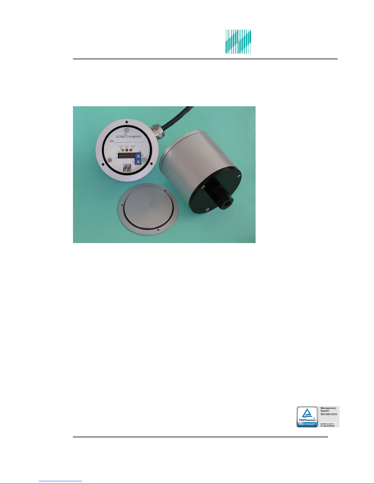
Electronic Vibration Monitoring Unit
ESW®-Compact-Alu (hol 10)
1. Generally basical safety-indications
Don’t use this device as the only invigilator, if a malfunctioning of ESW®-Compact-Alu
could lead to damages on goods or Persons.
To obtain the desired result be sure, that the device with its technical data fits to the
bulk of the object you want to supervise.
The sensor is sensitive to shock. A downfall out lower height to a hard substratum can
destroy the sensor.
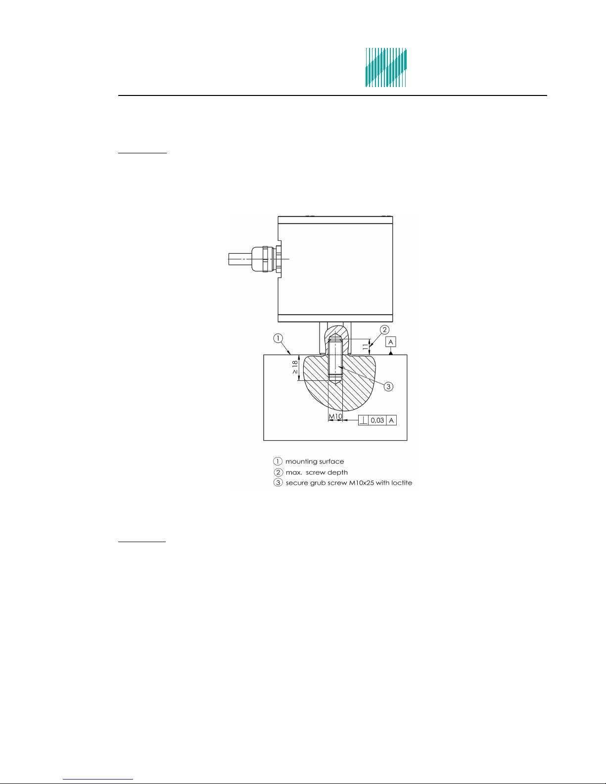
The assembling place and the execution of the assembling of the sensor determine
decisively the quality of the sensor signal. The assembling may only happen through
qualified and instructed persons.
The electrical hook up is to be done by instructed persons. A mistake by the connection
can entail to faulty functions, outfall or ruination of the sensor and electronics.
The ESW®-Compact-Alu should not be used on machines with a very energetic high-
frequency solid-borne. Through resonance apparitions in the sensor, the device can
indicate a much too great or too small value.
Powerful noise sources for instance inverters, in direct closeness of the sensor,
electronics or cabling, can result in faulty behaving of the apparatus.
Potential differences and balance currents in the mass guidance can result in faulty
behaving too.
The connection cable is resistant against many but not every type of chemicals.
Through a damaged cable chemicals could get inside the unit and destroy the
electronic. Then the unit would loose their function.
Therefore the conditions from the mounting surrounding must be checked. Then the
cover material from the cable have to be proofed if it resists these requirements. You
can get an overview from the chemical resistance of the cover material from us.
2. acking and the transport
Note:
The sensor is sensitive to shock. A downfall out lower height to an hard
substratum can destroy the sensor.
Avoid to kink or tie a knot in the cable.
Keep the electronic in a dry place.
In case of a downfall or heckling or squeezing, could the casing or the
operation elements or the board get defects.
With adequate warning-labels and through a qualified packaging and storage, you can
protect the sensor and electronics at carriage against influences from outside.
4