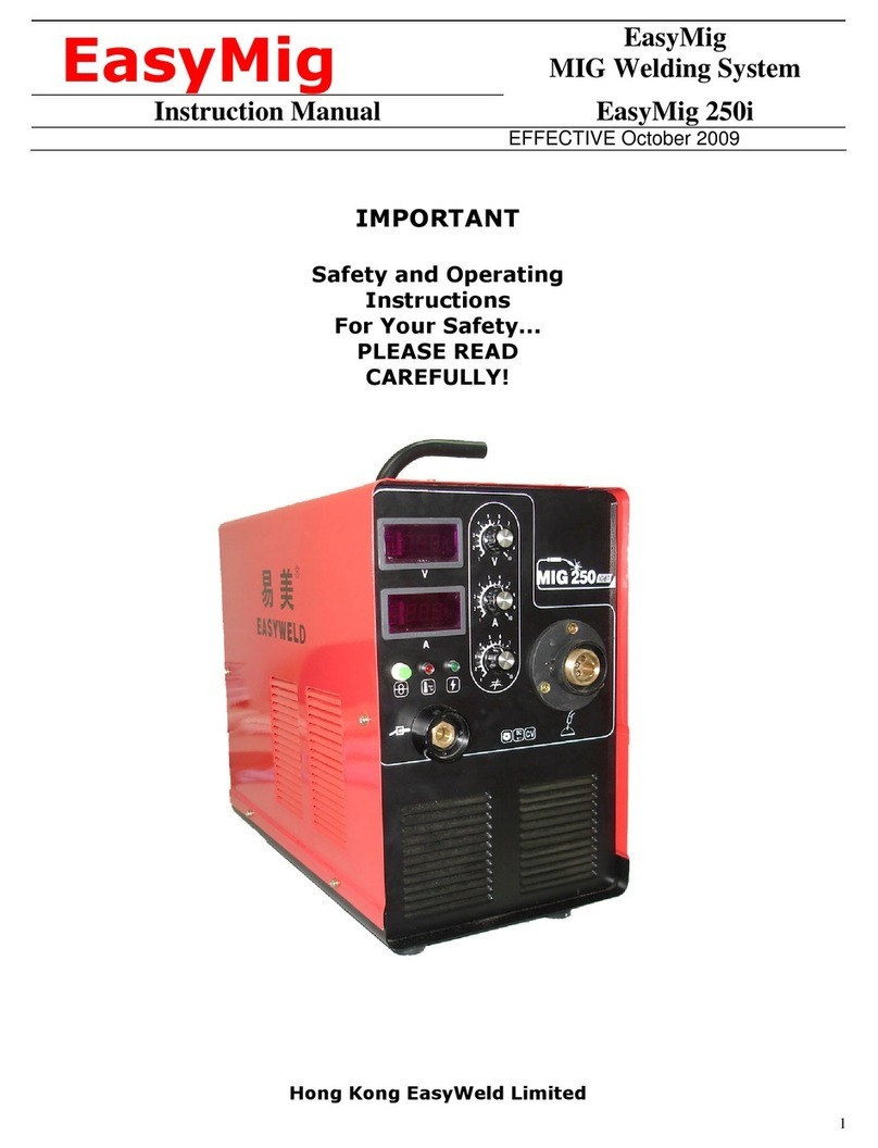
Hong Kong Easyweld EasyArcARC 200 User manual

1
EasyArc
ARC 200/ ZX7-300/ ZX7-400
INVERTER MMA WELDING
MACHINE
OPERATION MANUAL
Hong Kong E syweld Limited

2
CONTENTS
- Contents & Declaration of Conformity 2
- Warnings & Safety Information 3
- General Description & Block Diagram 6
- Eq ipment Specification & Circ it Diagram 7
- Installation & Operation 8
- Checks, Ca tions, Safety Tips 9
- Maintenance & Tro bleshooting 10
EC DECLARATION OF CONFORMITY
Hereby we declare that o r machines for ind strial and professional se as
stated below:
Types: EasyArc 200/ EasyArc ZX7-300/ EasyArc ZX7-400
Conform to the Low Voltage Directive: 73/23/EEC and EMC Directive:
89/336/EEC. E ropean Standard: EN60974-1:1 998+A1:2000+A2:2003 and:
EN60974-1 0:2003 respectively.
Please read and nderstand this instr ction man al caref lly before installation
and operation of the eq ipment.
This revised instr ction man al was iss ed on 1st November 2008.

3
WARNING
Welding and c tting is dangero s to the operator, other people in, or near, the
working area, and the s rro nding environment, if the eq ipment is not
correctly operated. Therefore, the performance of welding/c tting m st be
carried o t nder the strict and comprehensive observance of all relevant safety
reg lations.
Please read and nderstand this instr ction man al caref lly before the
installation and operation
S fety Prec utions — Re d before using this equipment
ELECTRIC SHOCK c n kill
To ching live electrical parts can ca se fatal shocks or severe b rns. The
electrode and work circ it is electrically live whenever the machine is switched
on. The inp t power circ it and machine internal circ its are also live when
power cable is connected to the mains s pply. Incorrectly installed or improperly
earthed eq ipment is a hazard.
• Do not to ch live electrical parts.
• Wear dry, hole-free ins lating gloves and body protection.
• Ins late yo rself from the work-piece and gro nd by sing dry ins lating
mats or covers big eno gh to prevent any physical contact with the work or
gro nd.
• Do not to ch the electrode if yo are in direct contact with the work-piece
• Always make certain that this eq ipment is correctly earthed
• Check the inp t cable reg larly for damage or bare wiring have it replaced
immediately if damaged, by a competent person, remember bare wiring can
kill
• Do not se worn, damaged or ndersized cables
• Do not drape or wrap cables aro nd yo r body
• Make s re that all panels and covers are sec rely in place when sing this
eq ipment
• Always make s re that o tp t cables are sec rely fastened to the o tp t
sockets
• Always clamp the work cable with clean metal to metal contact to the
work-piece or bench as near to the welding area as possible
Important!
Inverters carry a significant amount of DC voltage even after they have been
disconnected from the mains supply. Do not remove the covers or touch any
internal components before the input capacitors have been properly discharged
by a trained and competent person!

4
FUMES nd GASES c n d m ge your he lth
The f mes and gases prod ced when welding can be hazardo s to yo r health.
Avoid breathing these f mes
• Keep yo r head o t of the f mes, do not breathe them in.
• If indoors ventilate the area well and/or se local extraction ventilation
eq ipment to remove f mes and gases
• When welding in confined spaces of areas of poor ventilation se an
approved air s pplied respirator system
• Read and nderstand the electrode man fact rers’ health and safety data
sheets
• Do not weld in areas near de-greasing, cleaning or spraying operations. The
vapors can react with the heat and rays of the arc to form highly toxic and
irritating gases.
• Do not weld on coated metals i.e. galvanized; lead or cadmi m plated
metals nless the coating has been completely removed from the welding
area. The coatings can give off highly toxic f mes if welded.
ARC RAYS c n burn the eyes nd skin
The welding arc prod ces intense visible and invisible (Ultraviolet and infrared)
rays that will b rn the eyes and skin.
• Wear a welding helmet fitted with the correct shade of filter to protect yo r
face and eyes, when welding or watching
• Wear approved safety glasses with side screens nder yo r welding helmet.
• Use protective screens or barriers to shield the working area and protect
others from arc-flash and glare; warn others not to watch the arc.
• Wear protective clothing made from leather or thick flame-resistant material.
Cover all exposed skin areas.
FLYING PARTICLES c n injure eyes.
Welding, chipping, wire br shing and grinding can ca se sparks and flying
particles. Slag can be thrown off the weld as it cools.
• Always wear approved safety glasses with side shields even nder yo r
welding shield.
WELDING c n c use fire or explosion
Welding ca ses sparks to fly off the arc. Hot eq ipment, flying sparks and the
hot work-piece can ca se fires and explosions. Welding on closed containers or
pipe-work can ca se rapid expansion of the gases within them res lting in
possible explosion.
• Remove any flammable materials from the welding area. Do not weld in an
area where flying sparks can ignite flammable materials.
• Use flame proof blankets to shield any possible ca ses of ignition from flying
sparks or hot metal/slag
• Keep a fire exting isher nearby and watch for fire, partic larly on the hidden
side of any working area.
• Do not weld on closed containers, tanks, dr ms or pipes nless they are
properly and safely vented.
• Always wear oil and grease free flame-proof protective clothing.
• Always remove comb stible/ flammable materials from the working area prior
to commencing any welding operation.

5
• Connect earth/work cables as close as possible to the welding zone to prevent
welding c rrent from traveling long paths and possibly ca sing electric
shocks or fire hazards.
NOISE c n d m ge he ring
Noise from some welding/c tting processes can exceed recognized safe levels
ca sing both temporary and permanent hearing loss.
• Wear ear protection if noise level exceeds recommended limits.
MAGNETIC FIELDS c n ffect p cem kers
• The strong magnetic fields ca sed by the arc welding process and eq ipment
can affect pacemakers.
•Wearers of pacemakers sho ld keep away from the welding area and cons lt
their doctor before going near any arc welding, go ging or c tting processes.
LIMITED WARRANTY
The machine is insured against damage upon shipping. If you machine is damaged
in any way when you receive it, you must retain all shipping materials and packing.
Call our customer service department and report the damage immediately.
There is a 1 year warranty on all internal electronic parts. The torch, cables, power
cord, clamps, air regulator, hoses, case & paint and consumables are not covered
under warranty. You must use dry air via the air regulator and empty the reservoir
from the water separator frequently to insure proper protection from moisture.
This machine is designed to operate from 200~240VAC/380VAC at 50-60Hz Only.
Operating outside of limits will void warranty.
Warranty coverage covers repair or replacement of damaged machine or
damaged circ it board. Warranty does not cover shipping from the c stomer b t
does cover ret rn shipping within the Cont. United States. If yo are going to
ret rn a machine to s for repairs, it m st be well packed and ins red.
C stomers who own machines that req ire warranty coverage sho ld contact
o r warranty department by email at info@hkweld.com to obtain a ret rn
a thorization code.
C stomers who own an o t-of-warranty machine that req ire repairs sho ld
contact s for an estimate.

6
GENERAL DESCRIPTION
These welding machines are man fact red with advanced inverter technology.
With power MOSFET and PWM technology, the inverter converts DC voltage,
which is rectified from mains inp t AC voltage, to high (100 KHz) freq ency AC
voltage; s bseq ently, the voltage is transformed and rectified to give a smooth,
stable D.C. o tp t. Working at 100 KHz req ires a m ch smaller main
transformer and res lts in a lighter weight inverter welder, with an increased
d ty cycle. The high freq ency oscillation, which enables the o tp t of high
freq ency DC, is employed in the arc-starting system. The feat res of this
prod ct are as follows: stable c rrent, reliable, completely portable, efficient
and low noise o tp t.
The feat res of the MMA series are: efficiency, energy saving, portability,
excellent dynamic characteristics and stable arc, relatively low no-load voltage,
the ability to meet a wide variety welding req irements.
The cases of the EasyArc 200 model are made from a high impact flame
resistant engineering plastics material. This res lts in a more attractive, d rable
and water resistant machine.
G arantee of maintenance for main power so rce is 12 months, excl ding
cables, g ns, torches and accessory items.
D ring the g arantee maintenance period, all maintenance is free of charge, b t
does not incl de deliberated damage, or damage ca sed by mis se of this
welding eq ipment. Only q alified technicians are a thorized to carry o t repairs
of this welding eq ipment in the case of machine breakdown.
BLOCK DIAGRAM

7
EQUIPMENT SPECIFICATIONS
TYPE EasyArc
160
EasyArc
200
EasyArc
ZX7-300
EasyArc
ZX7-400
Inp t
voltage(VAC)
220±15% 380±15%
Inp t Freq ency
(Hz)
50/60 50/60 50/60 50/60
Rated
inp t(KVA)
5.3 7 12 18
Rated o tp t
voltage
27 28 28 27
O tp t
c rrent (A)
20-160 20-200 20-300 20-400
Drive c rrent
range (A)
-- -- 20-270 20-360
D ty cycle % 60 60 60 60
No-load
voltage(V)
70 70 55 65
No-load loss(W)
40 40 40 40
Efficiency % 85 85 85 85
Power factor 0.93 0.93 0.93 0.93
Ins lation class B B F F
Protection class 1P23 1P23 1P23 1P23
Weight(kg) 6.5 6.5 10 8
Table 1
CIRCUIT DIAGRAM (Single-ph se input)
I
F

8
INSTALLATION & OPERATION
1. Connection of Power Supply C bles
A primary power s pply cable is fitted to this welding eq ipment. Connect
the power s pply cable to the correct voltage, as stated on the rating plate
attached to the machine. The primary cable sho ld be fitted with the correct
pl g to avoid overheating.
2. Connection of Output C bles
Two twist lock sockets are sit ated on the front panel of this welding power
so rce. Insert the o tp t cable pl gs and twist to lock firmly. It is possible
to damage both the pl g and socket, if the pl g and the socket are
incorrectly or loosely connected.
For MMA welding the electrode holder cable sho ld normally be connected
to the positive terminal, while the work piece sho ld be connected to the
negative terminal. The two modes of connection of DC welding eq ipment
are as follows:
• Straight polarity: electrode holder to “-”, work piece to “+”;
• Reverse polarity: electrode holder to “+”, work piece to “-”
• [for D.C. Tig welding the electrode sho ld be negative (-ve)]
Connect according to the electrode man fact rer’s recommendations,
(normally displayed on the packet), as incorrect connection may ca se
nstable arc, spatter or freezing of rod to work piece etc. If the distance
between work piece and this power so rce is over 50 M, it may be
necessary to increase the diameter of cable in order to maintain voltage
o tp t.
Electrode
holder
Connection
Ground
Connection
Pilot Lamp
Power :Lamp
Ground
Connection
Electrode
holder
Connection
Arc Control
Current Meter
Arc Starting
Main Current
Power :Lamp
Main Current
Pilot Lamp

9
3. Power Supply Switch
While the power s pply switch is on, the b ilt-in fan works and c rrent
meter displays the c rrent val e.
4. Welding Current Output Setting
Set the c rrent o tp t by sing the “welding c rrent knob”
Approximate c rrent settings for different electrode sizes are as follows:
Ø1.6: 30-50A; Ø2.0: 40-80A; Ø2.5: 70-bOA; Ø3.2: 110-170A; Ø4.0:
130-240; Ø5.0: 200-360A
5. Pilot L mp
If the pilot lamp is on, it indicates that the eq ipment has over heated,
which possibly is the conseq ence of over d ty cycle operation. This
welding eq ipment a tomatically restarts when the temperat re inside the
machine drops to req ired level, and the pilot lamp t rns off.
6. Current Meter (fitted to E syArc ZX7-300 nd E syArc ZX7-400)
Digital meter indicates welding c rrent.
Operating d ty cycle
The operation of this welding eq ipment sho ld be strictly accordance with the
specification. Please refer to the table of Equipment Specifications (Table 1).
A s dden halt may occ r whilst the welding operation is being carried o t when
this welding machine is in an over-load state. Under this circ mstance, the
b ilt-in fan works to bring down the temperat re inside the welding eq ipment,
therefore it is nnecessary to disconnect the mains inp t of the welding
machine.
CHECKS
• This welding eq ipment is correctly earthed
• All the connections are made. Partic lar attention sho ld be drawn to the
connection of earth clamp and work piece.
• The o tp t terminals of electrode holder and earth cable are firmly attached.
• The o tp t polarity is correct.
• In cases where an earth leakage switch is sed, the maxim m earth leakage
is less than 30mA.
CAUTIONS
1. Working Environment
1.1 The location in which this welding eq ipment is installed sho ld be free
of excessive d st, corrosive chemical/ gases, flammable gas or
materials etc, and of maxim m 80% relative h midity.

10
1.2 Avoid the operation of welding in the open air nless the working area
sheltered from the s n, rain water and snow etc; the temperat re of
working environment sho ld be maintained within -10°C to +40°C.
1.3 The minim m distance of this welding eq ipment and any wall or other
object sho ld be 30 cm.
1.4 Keep the working environment well ventilated.
2. Safety Tips
2.1 Ventilation: This welding eq ipment is small in size, compact in
str ct re, and of excellent o tp t c rrent performance. Fans are to
extract heat generated by this welding eq ipment while the operation
of welding is carried o t.
C ution: Keep the lo vers of this eq ipment clear. The minim m
distance between this welding eq ipment and any other objects in or
near the working area sho ld be 30 cm. Good ventilation is of critical
importance for the normal performance and service life of this
apparat s.
2.2 Welding operation is interr pted whilst this welding eq ipment is in
over-load state. A s dden halt may occ r to the welding operation if
this welding machine is overloaded. Under this circ mstance, it is
nnecessary to restart this welding eq ipment. Keep the apparat s
switched on and the b ilt-in fan working to bring down the temperat re
inside this welding eq ipment.
2.3 Over-voltage operation is prohibited. The power s pply voltage range of
the welding machine is stated in Table: 1. This welding eq ipment
a tomatically compensates for inp t voltages within the given range. In
cases where the inp t voltage of the power s pply exceeds the
stip lated val e, it is possibly damaging to the components of this
welding eq ipment.
2.4 It is strongly recommended not to to ch the o tp t terminals when the
welding operation is performed. An electric shock can occ r.
M inten nce
Expos re to extremely d sty, damp, or corrosive air can be damaging to the
welding machine. In order to prevent any possible fail re or fa lt occ rring with
this welding eq ipment, blow o t the d st at reg lar intervals with clean and
dry compressed air. (Be s re to wear s itable respiratory, eye, hand and
hearing protection whilst performing this operation).
Please note that: lack of maintenance can invalidate the warranty of this
welding eq ipment and that there are no ser serviceable parts contained within
this eq ipment. Warranty will be invalidated if the factory seals have been
broken.

11
TROUBLESHOOTING
C ution: Only the qu lified technici ns re uthorized to undert ke the
rep ir t sk of this welding equipment in c se of m chine f ult.
Fa lt Symptoms Diagnosis Corrective Action
While this welding eq ipment
is operated, the pilot lamp is
off, no o tp t, b ilt-in fan
navailable.
1. Possible fail re of inp t
voltage.
2. Possible fail re of inp t
power s pply.
3. This welding eq ipment is
possibly defective or
damaged.
1. Check and rectify.
2. Check mains f se and replace if
necessary.
3. Contact q alified repairer.
While this welding eq ipment
is operated, pilot lamp is off,
no o tp t, the b ilt-in fan
navailable. A s dden
sh tdown of the welding of
the welding eq ipment
occ rs.
1. The connection of power
s pply switch and bottom
board is navailable,
2. This welding eq ipment is
in protection state d e to
over-voltage on inp t
s pply.
3. Power s pply inp t is
nstable.
4. This welding eq ipment is
in over-voltage protection
state d e to contin o s
power on and power off of
the welding eq ipment.
5. Relay of 24V of power
board is possibly defective.
Replace it.
6. Power s pply fail re to of
top PCB.
1. Rectify the connection fail re.
2. Disconnect from mains s pply and
check inp t voltage sing a digital
m lti-meter.
3. Have power s pply checked by a
competent person.
4. Disconnect the power s pply, for at
least 5 min tes, reconnect & restart
the eq ipment.
5. Check and replace if necessary.
6. Check and repair if necessary.
While this welding eq ipment
is operated, pilot lamp is off,
no o tp t, however b ilt-in
fan is f nctioning.
1. Fa lty Connection inside
the welding eq ipment.
2. Fa lty control mod le,
drive circ it or drive
mod le.
3. Check MOSFET,
transformers, diode of
rectifier and connections.
1. Check and reconnect.
2. Replace as necessary.
3. Repair or Replace as necessary.
While this welding eq ipment
is operated, pilot lamp is on,
however no o tp t.
1. The welding eq ipment is
in over heating protection
state,
2. This welding eq ipment is
in over c rrent inp t
protection state.
3. Possible f nction fail re of
inverter nit. Disconnect
the power s pply cable
from the centre PCB.
3.1 If the fa lt indicator is
on, MOSFET of top PCB
is possibly defective.
3.2 if fa lt indicator is off:
3.2.1 Possible damage
of transformer of
centre PCB.
3.2.2 Possible damage
of secondary rectifier
of transformer.
4. Possible damage of feed
back circ it.
1. Leave switched on and allows
cooling for several min tes,
re-trying.
2. Have checked by a trained service
technician.
3. 3.2 Replace it, if necessary.
3.2.1 Replace it if necessary.
3.2.2 Replace it if necessary.
This manual suits for next models
2
Table of contents
Other Hong Kong Easyweld Welding System manuals
Popular Welding System manuals by other brands

Everlast
Everlast PoweTig 185 Micro Operator's manual

Harbor Freight Tools
Harbor Freight Tools VULCAN MIG GUN LINER Owner's manual & safety instructions

Jasic
Jasic CUT60 (L204) Operator's manual

ESAB
ESAB EMP 205ic AC/DC instruction manual

Miller
Miller Continuum 350 owner's manual

Lincoln Electric
Lincoln Electric STT-10 HEAD & CONTROLS BOOM MOUNT OR BENCH MODELS... Operator's manual