Horizon Fitness KRONOS100 User manual

---- KRONOS100 integrated surveying GPS receiver
Operation Manual

2
CONTENTS
CHAPTER I RECEIVER & ACCESSORIES........................................................................................................4
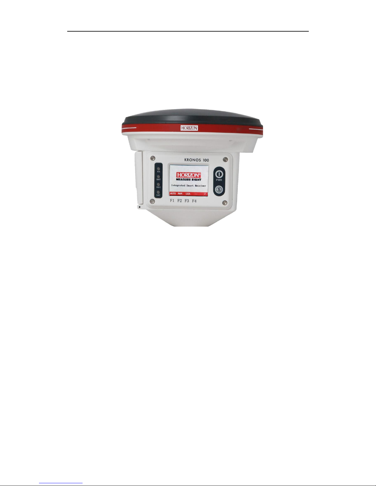
1.1 RECEIVER..........................................................................................................................................................................4
1.2 ACCESSORIES....................................................................................................................................................................4
1.2.1Controller ................................................................................................................................................................4
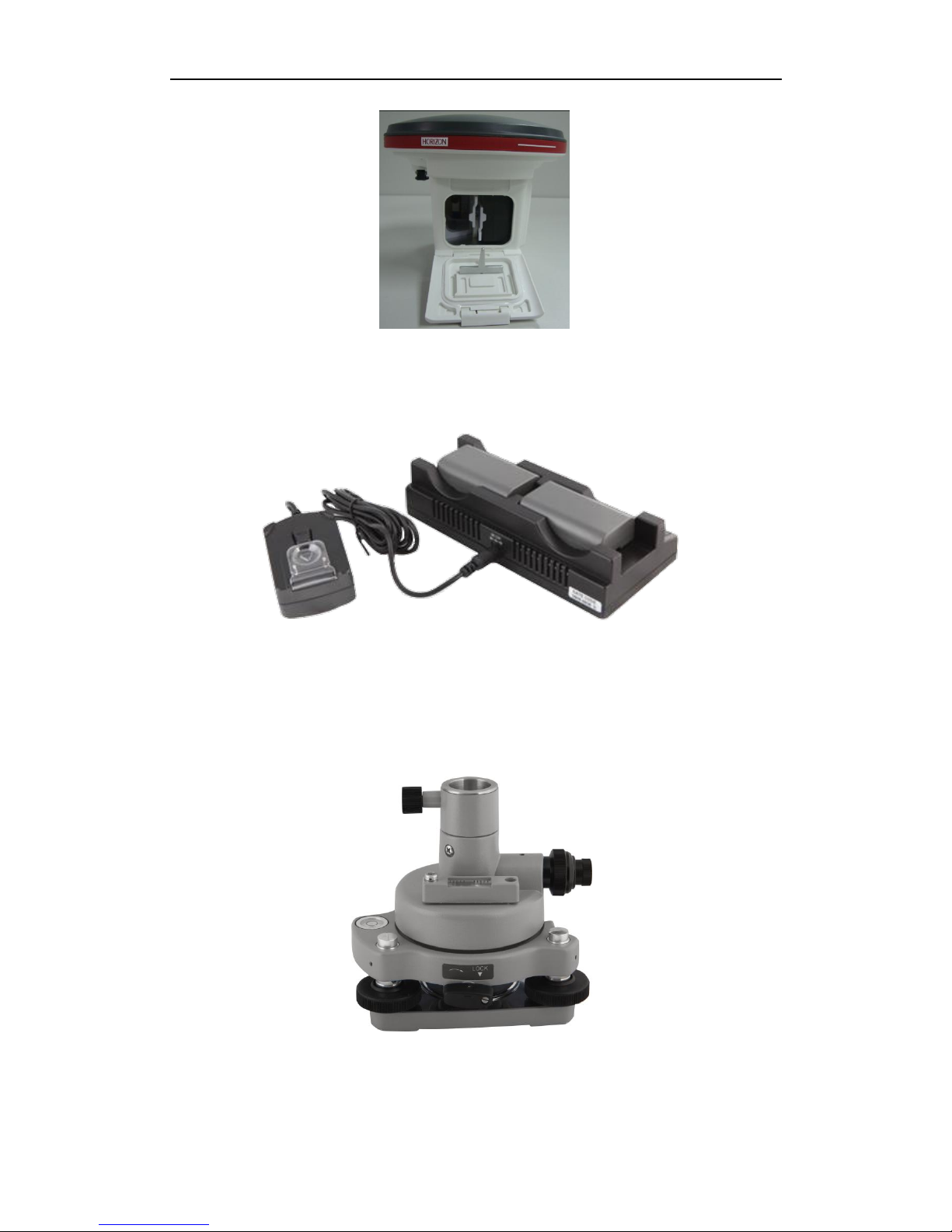
1.2.2 Battery and Charger .........................................................................................................................................5
1.2.3 Tribrach & plummet ..........................................................................................................................................6
1.2.4 Communication cable........................................................................................................................................7
1.2.5 Soft bag...................................................................................................................................................................7
1.3 SOFTWARE OF KRONOS100 GNSS SURVEY SYSTEM .............................................................................................7
CHAPTER II PREPARING WORK.....................................................................................................................9
2.1 WORKING MODE OF KRONOS100 RECEIVER ...........................................................................................................9
2.2 GRAPH DESIGN OF NET ...................................................................................................................................................9
2.3 WORKING RANGE..........................................................................................................................................................10
2.4 FIX THE RECEIVER IN THE FIELD ................................................................................................................................11
2.5 HOW TO MEASURE ANTENNA HEIGHT.......................................................................................................................11
2.6 NOTICE OF USING KRONOS100 RECEIVER ............................................................................................................11
CHAPTER III OPERATION IN THE FIELD ..................................................................................................13
3.1 MAIN INTERFACE...........................................................................................................................................................13
3.1.1 Initialize interface...........................................................................................................................................13
3.1.2 System interface...............................................................................................................................................13
3.2 OPERATION IN THE FIELD............................................................................................................................................18
3.2.1 AUTO Mode.........................................................................................................................................................18
2.2.2 MAN. Mode Collecting..................................................................................................................................... 20
2.2.3 LED mode............................................................................................................................................................22
CHAPTER IV KRONOS100 DIFFERENTIAL GPS SYSTEM.....................................................................23
4.1 WORKING MODE ..........................................................................................................................................................23
4.2 THE INITIALIZATION INTERFACE ...............................................................................................................................23
4.3 STEPS OF FIELD WORK................................................................................................................................................23
4.4 DYNAMIC POST-PROCESSING SOFTWARE...................................................................................................................28
4.4.1 Software start-up & operation brief.........................................................................................................28
4.4.2 Main menu & function introduction.........................................................................................................28
CHAPTER V MANUAL OF KRONOS STATIC MANAGER .........................................................................32
5.1 BRIEF INTRODUCTION..................................................................................................................................................32
5.1.1 Import record data..........................................................................................................................................32
5.1.2 Device Setting....................................................................................................................................................33
5.1.3 Register................................................................................................................................................................33
5.1.4 Firmware Upgrade..........................................................................................................................................35
APPENDICES ......................................................................................................................................................38
ASPECIFICATION ..............................................................................................................................................................38

3
BSTANDARD PACKING .....................................................................................................................................................39

4
Chapter I Receiver & Accessories
1.1 Receiver
KRONOS100 receiver integrates antenna, circuit board and main board in a single housing.
The waterproof, dustproof and drop resistant housing allows it to operate in the toughest
environments. The Kronos 100 is built with simplicity and durability in mind.
Figure 1-1 KRONOS100 receiver
The front panel consists of a large LCD color display, four display LEDs and two buttons. The
four LEDs are RX/BAT/REC/SAT. RX is the controller communication LED, and shows
whether the controller is connected or not. BAT is the power LED. REC is showing recording
interval. These LEDs will indicate when you select LED mode (LED mode, please refer to
chapter III). SAT is the satellite indicator LED.
These are two keys on receiver, one is power key, and another is S key, the function of which
is to communicate with controller.
For initial connection between controller with receiver, press S key once, then press
any button on controller to establish connection between receiver and controller.
To clear the connection, press and hold S key.
Battery slot is in the side of the receiver. There is one port in the back of receiver, which uses
a 7pin connector, to communicate with PC and download raw data from receiver to PC.
1.2 Accessories
1.2.1Controller
This controller has 16 keys. Number keys from 0-9. There are four function keys: F1, F2,
F3 and F4. The other two keys, Fa and Fb, currently not in use.

5
Figure 1-2 Controller
1.2.2 Battery and Charger
A. Battery
The receiver uses rechargeable lithium batteries. It can last 7.5 hours continuously and
needs five hours to recharge.
Figure1-3 lithium-battery
Installing the battery
1. Open the cover of batteries slot, see the following figure:
Figure 1-4 open the cover
2. Install the batteries, see figure 1-4.
Please push this
button towards to
bottom

6
Figure 1-5 The Battery compartment
Battery Charger
When recharging battery, the LED will display red. When batteries are fully charged, the LED
will display green. If the charger does not connect with battery, the LED is also red.
Figure 1-5 Chargers
1.2.3 Tribrach & plummet
KRONOS100 GPS receiver uses standard optical tribrach & plummet
Figure1-6 tribrach &plummet

7
1.2.4 Communication cable
KRONOS100 receiver uses a USB cable to connect to PC. One end has 7pins, and there are
two connectors on the other end, a COM connector and a USB connector. The USB port is
used to connect receiver to PC, and download data from receiver. The COM port is used to
upgrade firmware for the receiver.
Figure 1-7 communication cable
1.2.5 Soft bag
KRONOS100 soft bag is a durable soft casing to carry and store the KRONOS 100 receiver.
Figure 1-8 Soft bag
1.3 Software of KRONOS100 GNSS Survey System
A. Firmware software
This is the firmware software, used to record raw data in the field.
B. Downloading software (KRONOS STATIC MANAGER)
It is used to download data from receiver to computer and to register code for receiver.
C. Post-processing software
This software is used to process and adjust the raw data recorded in receiver.

8
Figure 1-9 post processing software

9
Chapter II Preparing work
2.1 Working mode of KRONOS100 receiver
GPS working mode is the working measure adopted to ensure the relative position between
observation stations by use of GPS orientation technology. Different working mode has
different working measure and different time interval of observation. KRONOS100 GPS
surveying system is mainly used in control survey, which adopts static carrier wave relative
orientation mode.
2.2 Graph design of net
The net design mainly subject to the users’ requirement, but outlay, time interval of
observation, type of receiver and the receiver amount, etc also relate to the net design.
In order to satisfy the users’ requirement, we should keep the principle as follows:
1. GPS net normally forms closed graph by independent observation borders, such as triangle,
polygon or connecting traverse, etc, to add checking conditions and to improve the net
consistency.
2. When designing the net, the net point should be superposition with the original ground
net points. The superposition points are generally no less than three and distribute evenly
on the net in order to ensure the changing parameters between GPS net and local net.
3. GPS net point should be superposition with the level points, and the other points are
normally united—surveyed with level surveying way or the equivalent way. You can also set
some level united—surveying points in order to offer geoid’s information.
4. In order to observe and level united survey, we often set GPS net points at a clear and easy
arriving field.
5. We often distribute some well eyeshot azimuth points around GPS net to ensure united
survey direction. The distance from azimuth to observation station should be more than 300
meters.
According to different purpose of GPS surveying, independent observation borders of GPS
net should compose definite geometry graph. The basic graphs are as follows:
1.Triangle net
The triangle in GPS net is composed of independent observation borders, it has strong
geometry structure and well self-checking ability, it can also find out the coarse difference of
result and to share the difference to each KRONOS100line with adjustment.
But this net need a lot of observation, especially when receivers are lacking it will greatly
prolong the observation time. So only when accuracy and security are required very high,
and receivers are more than three, we can use this graph, see fig 2-2.
2. Circle net
Circle net is composed of many loops which are formed of many independent observation
borders. This net is similar with one of the classical surveying-- lead net. Its structure is a
little worse than triangle net. The amount of KRONOS100 lines in closed loop decides the
self--checking ability and consistency. General speaking, the amount of KRONOS100 lines
has such limit as follows:

10
The advantage of circle net is the small workload, good self-checking and consistency. But
the main disadvantage is that the accuracy of indirect-observed border is lower than that of
direct-observed border, and the KRONOS100 line accuracy of neighbor points distributes
unevenly. In field surveying, we usually use annexed traverse as special example according
to practical situation and the net usage. This requirement for this traverse is the high
accuracy for the known vectors between two point ends. Furthermore, the amount of
annexed traverses cannot exceed the limits.
Fig 2-1 triangle net Fig 2-2 circle net
3. Star shape net
Star net has simple geometry graph, but the KRONOS100lines of it mostly don’t compose a
closed graph, so it has a bad checking ability and consistency.
The advantage of this net is that it only needs two receivers, the work is very simple, so it is
mostly used in the quick surveying as quick static orientation and kinematical orientation.
This working mode is widely used in project layout, border surveying and GIS surveying, etc.
Figure 2-4 star net
2.3 Working range
The accuracy of satellite signal received with GPS receiver can reach millimeter level, but
due to the signal suffers ionosphere and troposphere infection when transmitting through
aerosphere, the accuracy will be depressed. To settle this problem, we adopt adjustment by
use of two receivers to observe one KRONOS100line at the same time, thus the influence of
ionosphere on observation can be mostly counteracted. The shorter of KRONOS100line, the
better is the effect, so we suggest KRONOS100line is not more than 20 kilometers when
designing.

11
2.4 Fix the receiver in the field
Steps of fixed receiver:
1. You can mount a tripod on a selected point. Please make sure the surrounding meet
these conditions: avoid under shade and building, keep away from reflecting things and
electromagnetism interfering, etc.
2. Open the instrument case firstly; then take out plummet and the tribrach and mount on
the tripod, center and level the plummet & tribrach on the surveying point.
3. Take out receiver, fix it on the plummet & tribrach and lock it tightly.
2.5 How to measure antenna height
After fixed the instrument, user should measure antenna height at the beginning and the
end of every period of time to ensure the accuracy “mm” level. We usually measure from the
center point on the ground to the center waterproof loop of antenna. That is an inclined
height. Please refer to fig 2-5.
Fig2-5 Measuring antenna height
We use a formula to calculate antenna height.
H h R h
20
20
(2-3)
“h” is the inclined height that measure from point on the ground to the waterproof loop of
antenna.
R
0
is the radius of antenna.
h
0
is the distance from antenna phase center to the middle of antenna.
H is the calculation result. We usually measure antenna height twice and adopt the
average.
Attention: We input the inclined height as the antenna height, which is the inclined
distance from point on the ground to the waterproof loop of antenna.
2.6 Notice of using KRONOS100 receiver
When you use KRONOS100 receiver, please pay attention to the following items.
1. You must operate according to this manual to ensure the required result. For example,
when you select surveying point, you should avoid shade, buildings, interfere fountain and so
on.
2. The receiver should not work under low power; otherwise, the data quality cannot be

12
ensured.
3. When conveyed the mainframe, please be careful.
4. Please ensure that receiver should be used once every three month. Otherwise, the data
stored in the EMS will be lost, and when you use the receiver next time, the receiver will
take a long time to initialize .

13
Chapter III Operation in the field
Connecting controller with receiver
The first time you want to connect controller with mainframe, you can press S key quickly,
then press any button on controller, it will build connection between receiver and controller.
If you want to clear the connection, you can press and hold S key.
3.1 main interface
3.1.1 Initialize interface
Power on KRONOS100 receiver, you will see the initialization interface as following:
F1 F2 F3 F4
Figure 3-1 Vector KRONOS100 Initialization interface
1. Mode select in initialization interface
There are three modes in the initialization interface, which are AUTO, MAN and LED., with
the default being AUTO mode.
a. AUTO mode
It is a very intelligent collecting mode, the receiver can evaluate if the condition meets the
requirement and then auto enter the collection status. At the same time, you can see satellite
ephemeris and distribution.
b. MAN mode
This mode needs you to estimate if the collecting condition meets the requirement, which
asks for PDOP less than 6 and in the 3D status, you can input point name and period of time
number to enter the collecting state.
c. LED mode
At this state the LCD doesn’t work, you can only estimate the collection state according to
indicator lights.
2. Indicator lights
On the left of LCD screen, there are four indicator lights, which are RX light, battery
light ,recording light and satellite indicatory light from top to bottom.
If two batteries are both not enough, the power light will blink.
When it enters 3D, receiver will log data, the recording light will blink as time interval.
3.1.2 System interface
Select AUTO or MAN. to enter main interface. See figure as follows.

14
F1 F2 F3 F4
Fig 3-2 main interface of file system
The main interface includes three parts.
a. Satellite distributing graph
You can see how many satellites can be observed from this graph.
b. System prompt area
LSTIME: it shows local time.
RETIME: it shows that receiver logged time.
FREEMEM: it shows you the free memory of the receiver. For example, on the screen you
can see 16048K, which means the rest EMS memory is about15.6M. Power system and
battery showing:It shows that how much power is used.
c. Function key
If you want to use function key, please select the key on the controller. For example, select F1
to enter the “File” menu.
The introduction of every function key is as follows.
1. Press F1 to enter “file” interface, see fig 3-3
F1 F2 F3 F4
Fig 3-3 second interface of file
You can view the data storage state in the file interface.
If you select MAN., you will see point names on the screen.
Press F1, to enter next page.
Press F2, to enter previous page.

15
Press F3, to select a file in the current page.
Press F4, to return main interface.
2. Press F2 to enter “set” interface, see fig 3-4.
F1 F2 F3 F4
Fig 3-4 second interface of “set”
Press F1 to set the collecting interval, the default value is 10 second. You can press F1 to
change the interval. Press F2 to change the mask angle, you can change it from 0 degree to
45degrees. Press F3 to change the track times, which is used for Stop and go function.
After you finish all settings, press F4 to confirm, the setting will be saved.
Special notice: If several receivers are working at the same time, please set their mask angle
and collecting interval as the same.
3. Press F3 to enter “survey” interface, see fig 3-5.
F1 F2 F3 F4
Fig 3-5 second interfaces of “measure”
It includes five submenus: status, satellite, point name (collection), return and icon logging.
Press F1 to show LONG., LAT., ALT., PDOP, NAV. MODE, FIXED and number of visible satellite,
see figure 3-6.

16
F1 F2 F3 F4
Fig 3-6 second interfaces of “status”
Press F2, it will show ID of satellites and SN, see fig 3-7.
Press F3 in the AUTO mode, it will show point name. In the MAN mode, it will show
collection,see fig 3-8.
You can input the information of point in the fig 3-8, such as name of point, number of time
period of collection and antenna height.
Point name: please input four characters. the name should be as four characters.
Number of period of time: this is to select the surveying period for control point, it requires
to input the same file name and different period number before you move the control point.
Antenna height: the height of receiver. The method is to survey from point on the ground to
the blue seal waterproof loop.
F1 F2 F3 F4
Fig 3-7 second interface of “satellites”

17
F1 F2 F3 F4
Fig 3-8 input point information
Introduction of input method:
Press F1 to select a character among character segment.
F2 key is used to move cursor.
Press F3 continuously to select different characters segments, such as 0-9, A-G, H-N, O-U, V-Z.
Let’s use GPS1 as the point name to introduce:
(1). Select the characters segment from A to G with key F3.
(2). Use F1 to select the letter G from the above characters segment, thus character G is
inputted.
(3). Use key F2 to move the cursor..
(4). Repeat the steps until input the whole name “GPS1”.
(5). Press F4 to finish this operation.
When the cursor moves to “period of time input” and “antenna height input”, input them
according to the way above, press F4 to confirm it and return to the main interface.
4. Press F4 to enter “system” interface, see fig 3-9
F1 F2 F3 F4
Fig 3-9 system

18
F1 key: switch LED or not
F2 key: power off
F3 key: the information of the firmware.
5. Long press PWR turn off the receiver.
3.2 Operation in the field
Power on KRONOS100 receiver, there are three collecting modes in the initialization
interface, You need to select one of them within ten seconds, otherwise, the system will
enter “Auto Mode” automatically.
3.2.1 AUTO Mode
1. Data collecting
Press F1 to enter AUTO mode, see fig 3-10.
F1 F2 F3 F4
Fig 3-10 automatic interface
Enter AUTO mode, software will auto estimate the orientation status and the PDOP value.
You do not need make any operation; the software will enter the data collect status when
PDOP meets the requirement. You can see the increasing time in the right side, which means
KRONOS100 mainframe is logging the GPS data. You can name the logging data or the
software will set the default name as “****”. The file construction is set according to collecting
turns, if you want to reset the file name, please change it when logging the data, you can also
rename it according to the operation below:
2. Name a file for the saved data:
a. Press F3 to enter “survey” interface, you can see the single point geodetic coordinates,
receiver status, positioning status and PDOP.

19
F1 F2 F3 F4
Fig 3-11 “survey” interface
b. Press F3 to enter point name input interface, you can name the logging data, input period
number and antenna height here, see as:
F1 F2 F3 F4
Fig 3-12 name interface
Note: The different between AUTO and MAN: In AUTO mode, the receiver names the data
when logging it, but in MAN mode, you should input the point name and press the key to
start log date.
3. End logging data:
Firstly, you should end to log the data, before you power off the receiver. Please refer to
figure 3-11, when the time is enough, you can press “F4” to end logging.
4. Power off receiver.
1). Use controller to operate the receiver back to the main interface and long press PWR key
on receiver to turn it off.
2). Switch to the interface as following figure, then press F2 to power off receiver.

20
F1 F2 F3 F4
Figure 3-13 power off receiver
2.2.2 MAN. Mode Collecting
1. Data collect
Power on receiver, enter MAN mode by pressing F2 key in the initialization, see fig 3-14.
In this mode, the receiver will not auto collects data until you confirm that the receiver status
meets the required condition, which is PDOP less than 6 and in 3D status. When conditions
are satisfied, press F3 to enter data collecting interface, see fig 3-15.
2. Name a logging file:
When conditions are satisfied, press F3 to enter file name input interface, see fig 3-12. When
you finish the input of file name, number of period of time and antenna height, press F3, the
receiver will begin to log data.
Table of contents