Horizon Hobby SCX6 JEEP User manual

AXI05000T1/T2
Before operating this vehicle, please read all printed materials thoroughly.
Horizon Hobby is not responsible for inadvertent errors in this manual.
INSTRUCTION MANUAL
BEDIENUNGSANLEITUNG
MANUEL D’UTILISATION
MANUALE DI ISTRUZIONI
Scan the QR code and select the Manuals and Support quick links from the
product page for the most up-to-date manual information.
Scannen Sie den QR-Code und wählen Sie auf der Produktseite die Quicklinks
Handbücher und Unterstützung, um die aktuellsten Informationen zu Handbücher.
Scannez le code QR et sélectionnez les liens rapides Manuals and Support sur la
page du produit pour obtenir les informations les plus récentes sur le manuel.
Scannerizzare il codice QR e selezionare i Link veloci Manuali e Supporto dalla
pagina del prodotto per le informazioni manuali più aggiornate.

2
EN
Age Recommendation: Not for children under 14 years.This is not a toy.
WARNING: Read the ENTIRE instruction manual to become familiar with the features of the product before operating. Failure to operate
the product correctly can result in damage to the product, personal property and cause serious injury.
This is a sophisticated hobby product. It must be operated with caution and common sense and requires some basic mechanical ability. Failure to
operate this Product in a safe and responsible manner could result in injury or damage to the product or other property. This product is not intended for
use by children without direct adult supervision. Do not use with incompatible components or alter this product in any way outside of the instructions
provided by Horizon Hobby, LLC. This manual contains instructions for safety, operation and maintenance. It is essential to read and follow all the
instructions and warnings in the manual, prior to assembly, setup or use, in order to operate correctly and avoid damage or serious injury.
NOTICE
All instructions, warranties and other collateral documents are subject to change at the sole discretion of Horizon Hobby, LLC. For up-to-date
product literature, visit horizonhobby.com or towerhobbies.com and click on the support or resources tab for this product.
MEANING OF SPECIAL LANGUAGE
The following terms are used throughout the product literature to indicate various levels of potential harm when operating this product:
WARNING: Procedures, which if not properly followed, create the probability of property damage, collateral damage, and serious injury OR
create a high probability of superficial injury.
CAUTION: Procedures, which if not properly followed, create the probability of physical property damage AND a possibility of serious injury.
NOTICE: Procedures, which if not properly followed, create a possibility of physical property damage AND a little or no possibility of injury.
As the user of this product, you are solely responsible for operating in a manner that does not endanger yourself and others or result in damage
to the product or property of others.
This model is controlled by a radio signal subject to interference from many sources outside your control. This interference can cause momentary
loss of control, so it is advisable to always keep a safe distance in all directions around your model as this margin will help avoid collisions or injury.
• Never operate your model with low transmitter batteries.
• Always operate your model in open spaces away from full-size
vehicles, traffic and people.
• Never operate the model in the street or in populated areas for any
reason.
• Carefully follow the directions and warnings for this and any optional
support equipment (chargers, rechargeable battery packs, etc.) you use.
• Keep all chemicals, small parts and anything electrical out of the
reach of children.
• Never lick or place any portion of the model in your mouth as it could
cause serious injury or even death.
• Exercise caution when using tools and sharp instruments.
• Take care during maintenance as some parts may have sharp edges.
• Immediately after using your model, do NOT touch equipment
such as the motor, electronic speed control and battery, because
they generate high temperatures. You may burn yourself seriously
touching them.
• Do not put fingers or any objects inside rotating and moving parts, as
this may cause damage or serious injury.
• Always turn on your transmitter before you turn on the receiver in the
car. Always turn off the receiver before turning your transmitter off.
• Keep the wheels of the model off the ground when checking the
operation of the radio equipment.
SAFETY PRECAUTIONS AND WARNINGS
WARNING AGAINST COUNTERFEIT PRODUCTS: Always purchase from a Horizon Hobby, LLC authorized dealer to ensure
authentic high-quality Spektrum product. Horizon Hobby, LLC disclaims all support and warranty with regards, but not limited to,
compatibility and performance of counterfeit products or products claiming compatibility with DSM® or Spektrum technology.

3
EN
Your new Horizon Hobby vehicle has been designed and built with
a combination of waterproof and water-resistant components to
allow you to operate the product in many “wet conditions,” including
puddles, creeks, wet grass, snow and even rain.
While the entire vehicle is highly water-resistant, it is not completely
waterproof and your vehicle should NOT be treated like a submarine.
The various electronic components used in the vehicle, such as the
Electronic Speed Control (ESC), servo(s) and receiver are waterproof,
however, most of the mechanical components are water-resistant and
should not be submerged.
Metal parts, including the bearings, hinge pins, screws and nuts, as
well as the contacts in the electrical cables, will be susceptible to
corrosion if additional maintenance is not performed after running in
wet conditions. To maximize the long-term performance of your vehicle
and to keep the warranty intact, the procedures described in the “Wet
Conditions Maintenance” section below must be performed regularly
if you choose to run in wet conditions. If you are not willing to perform
the additional care and maintenance required, then you should not
operate the vehicle in those conditions.
CAUTION: Failure to exercise caution while using this
product and complying with the following precautions could
result in product malfunction and/or void the warranty.
GENERAL PRECAUTIONS
• Read through the wet conditions maintenance procedures and make
sure that you have all the tools you will need to properly maintain your
vehicle.
• Not all batteries can be used in wet conditions. Consult the battery
manufacturer before use. Caution should be taken when using Li-Po
batteries in wet conditions.
• Most transmitters are not water-resistant. Consult your transmitter’s
manual or the manufacturer before operation.
• Never operate your transmitter or vehicle where lightning may be present.
• Do not operate your vehicle where it could come in contact with salt
water (ocean water or water on salt-covered roads), contaminated
or polluted water. Salt water is very conductive and highly corrosive,
so use caution.
• Even minimal water contact can reduce the life of your motor if it
has not been certified as water-resistant or waterproof. If the motor
becomes excessively wet, apply very light throttle until the water is
mostly removed from the motor. Running a wet motor at high speeds
may rapidly damage the motor.
• Driving in wet conditions can reduce the life of the motor. The
additional resistance of operating in water causes excess strain. Alter
the gear ratio by using a smaller pinion or larger spur gear. This will
increase torque (and motor life) when running in mud, deeper puddles,
or any wet conditions that will increase the load on the motor for an
extended period of time.
WET CONDITIONS MAINTENANCE
• Drain any water that has collected in the tires by spinning them at high
speed. With the body removed, place the vehicle upside down and pull
full throttle for a few short bursts until the water has been removed.
CAUTION: Always keep hands, fingers, tools and any loose
or hanging objects away from rotating parts when performing
the above drying technique.
• Remove the battery pack(s) and dry the contacts. If you have an air
compressor or a can of compressed air, blow out any water that may
be inside the recessed connector housing.
• Remove the tires/wheels from the vehicle and gently rinse the mud
and dirt off with a garden hose. Avoid rinsing the bearings and
transmission.
NOTICE: Never use a pressure washer to clean your vehicle.
• Use an air compressor or a can of compressed air to dry the vehicle
and help remove any water that may have gotten into small crevices or
corners.
• Spray the bearings, drive train, fasteners and other metal parts with
a water-displacing light oil. Do not spray the motor.
• Let the vehicle air dry before you store it. Water (and oil) may
continue to drip for a few hours.
• Increase the frequency of disassembly, inspection and lubrication of
the following:
-Front and rear axle hub assembly bearings.
-All transmission cases, gears and differentials.
-Motor—clean with an aerosol motor cleaner and re-oil the
bushings with lightweight motor oil.
WATER-RESISTANT VEHICLE WITH WATERPROOF ELECTRONICS
TABLE OF CONTENTS
Water-Resistant Vehicle With Waterproof Electronics.............................3
Box Contents.....................................................................................................4
Required Equipment ........................................................................................ 4
Recommended Tools....................................................................................... 4
Getting Started Checklist................................................................................ 5
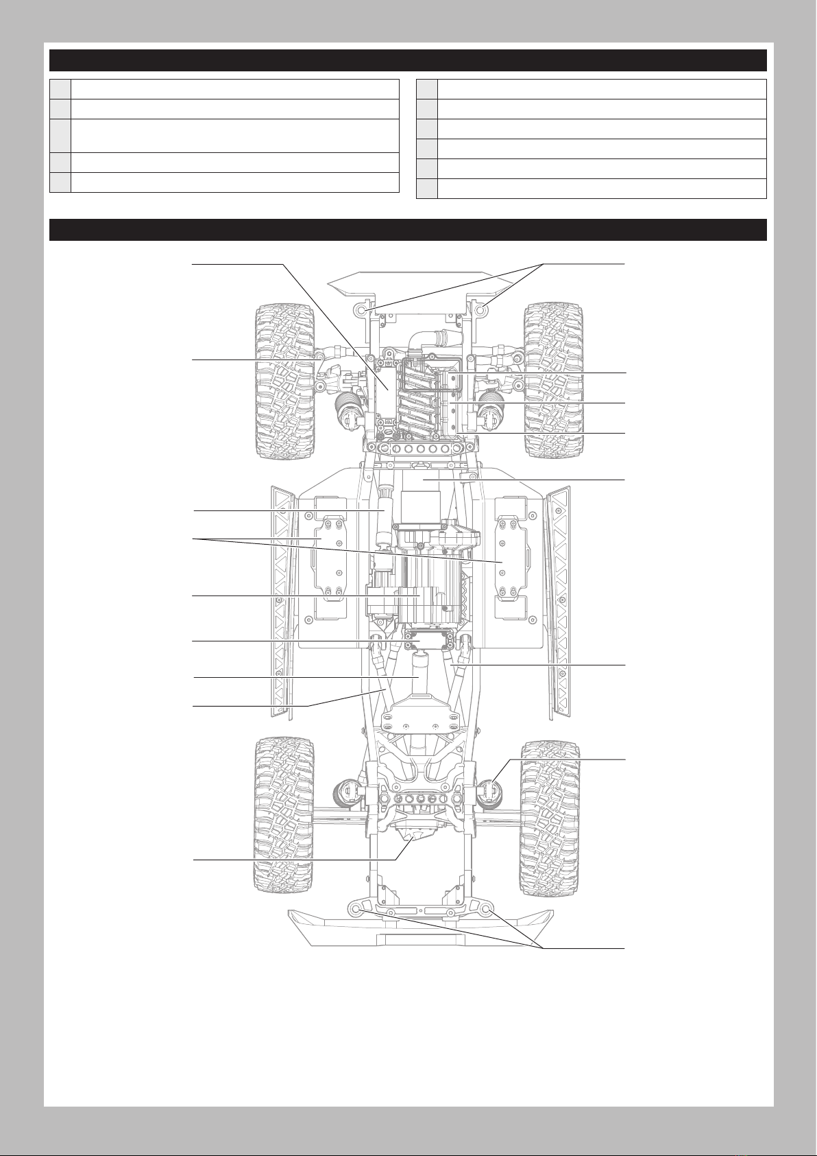
Vehicle Parts..................................................................................................... 5
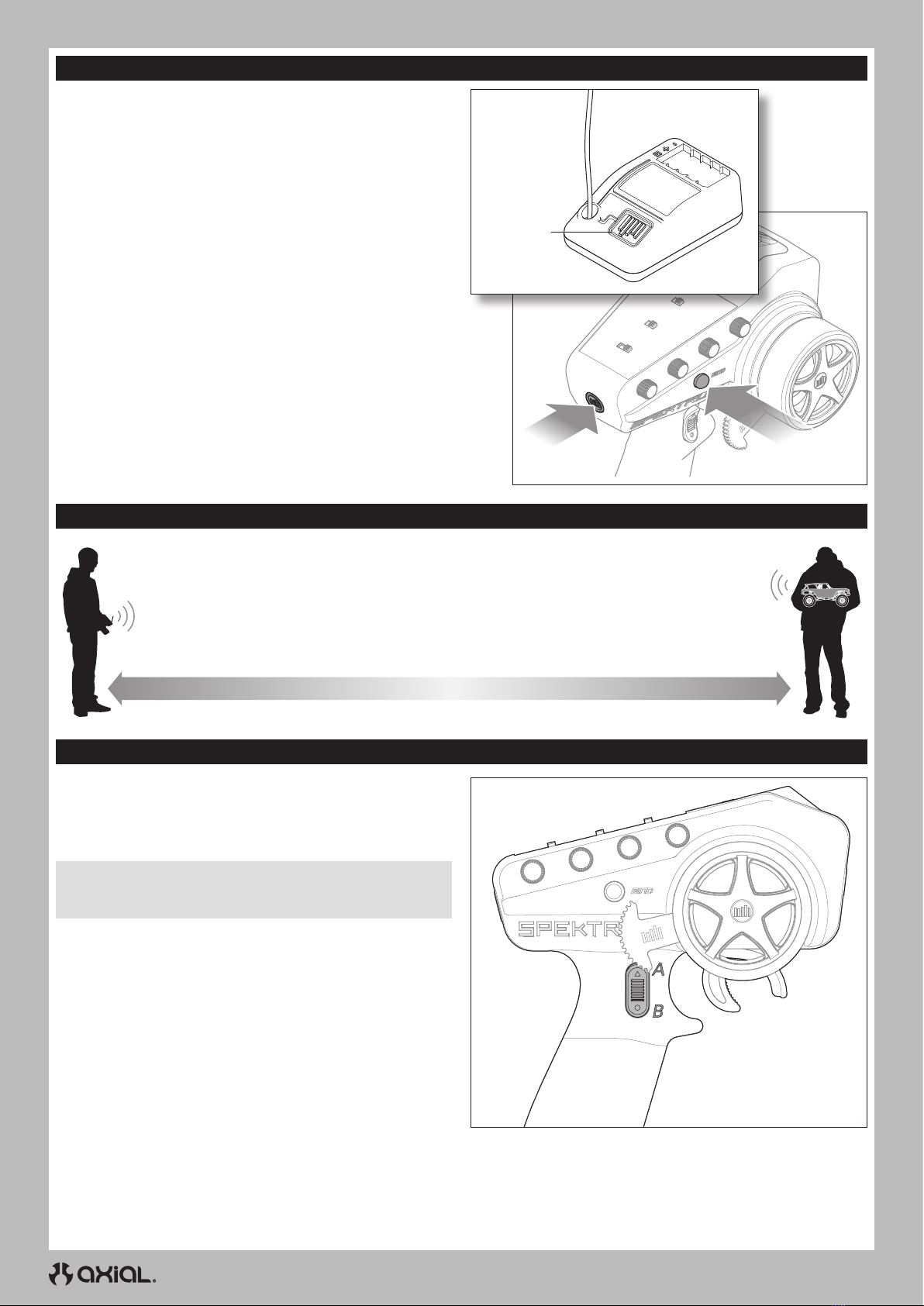
Charge the Vehicle Battery ............................................................................ 6
Install the Transmitter Batteries....................................................................6
Transmitter Functions......................................................................................6
Adjusting the Vehicle Battery Tray................................................................7
Install the Vehicle Battery .............................................................................. 7
Binding............................................................................................................... 8
Range-Checking the Radio System ..............................................................8
Using the Two Speed transmission...............................................................8
Vehicle Maintenance ...................................................................................... 9
ESC Operation.................................................................................................10
ESC Programming..........................................................................................10
Gear Ratios......................................................................................................11
Troubleshooting..............................................................................................11
Limited Warranty............................................................................................ 12
Warranty and Service Contact Information ..............................................13
FCC Information.............................................................................................. 13
IC Information.................................................................................................13
Compliance Information for the European Union.....................................14
Exploded Views..............................................................................................54
Parts List.......................................................................................................... 59
Electronics ......................................................................................................61

4
EN
BOX CONTENTS
• Battery charger compatible with
the chosen vehicle battery type
• Hex Drivers
(2.0, 2.5, 3.0mm) • Hobby
Knife • Side Cutter • Curved
Scissors • Long-nose Plier
RECOMMENDEDTOOLS
REQUIRED EQUIPMENT
• 3S Standard or “Shorty” LiPo Battery
(IC5®Connector Required)
• SCX6™1/6 Jeep JLU Wrangler RTR
- SR515 DSMR 5 CH Receiver (SPMSR515)
- 1200Kv 1/6 Brushless Sensored Crawler Motor (SPMXSM3100)
- 120A Crawl Smart Brushless Sensored ESC (SPMXSE1080)
- Water Proof S905 Large Scale Servo 15T (SPMS905)
- Water Proof Metal Gear Surface Servo (SPMS614)
• Spektrum™DX3™2.4GHz Transmitter (SPM2340T)
• 4 AA Batteries

5
EN
Steering Servo
Transmission Servo
Rear Driveshaft
Front Driveshaft
Upper 4-link Bar
Front Body Mount
Rear Body Mount
Lower 4-link Bar
Shock Absorber
VEHICLE PARTS
GETTING STARTED CHECKLIST
Read the manual
Familiarize yourself with the vehicle and its components
Check all screws, especially the driveshaft setscrews, for
tightness from the factory
Charge the vehicle battery
Install 4 AA batteries in the transmitter
Power on the transmitter
Install the vehicle battery in the vehicle
Check for proper function of the throttle and steering
Range check the radio system
Drive the vehicle, challenge yourself and have FUN!
Perform any necessary vehicle maintenance
Steering Knuckle
Battery Trays
Motor
Two Speed Transmission
Locked Differential
(inside axle housing)
ESC
(under top cover)
ESC Power Button
(on bottom)
Receiver
(inside receiver box)

6
EN
INSTALLTHETRANSMITTER BATTERIES
TRANSMITTER FUNCTIONS
This transmitter requires 4 AA batteries.
1. Remove the battery cover from the transmitter.
2. Install the batteries as shown.
3. Install the battery cover.
CAUTION: NEVER remove the transmitter batteries while the
model is powered on. Loss of model control, damage, or injury
may occur.
CAUTION: If using rechargeable batteries, charge only
rechargeable batteries. Charging non-rechargeable batteries
may cause the batteries to burst, resulting in injury to persons and/or
damage to property.
CAUTION: Risk of explosion if battery is replaced by an incorrect
type. Dispose of used batteries according to national regulations.
Channel 3 Button (Two-Speed Function)
Throttle/Brake
Steering Wheel
Steering Rate
Adjusts the end point of the steering
Brake Rate
Adjusts the braking end point.
SteeringTrim
Adjusts the steering center point. Normally, the steering trim is
adjusted until the vehicle tracks straight.
ThrottleTrim
Adjusts the throttle neutral point
SMART Battery Level Indicator
Servo Reversing
To reverse the Throttle (TH) or Steering (ST) channel, switch
the position of the correlating switch—“N” is for normal, “R”
is for reverse.
Throttle Limit
Limits throttle output to 50/75/100%
Select 50% or 75% for less experienced drivers or when you
are driving the vehicle in a small area.
Power LED
• Solid red lights: Indicates radio connectivity and
adequate battery power
• Flashing red lights: Indicates the battery voltage is
critically low. Replace batteries
Power Button
Bind Button
C
D
H
J
K
L
I
G
F
E
M
N
A/B
A/B.
C.
D.
E.
F.
G.
H.
I.
J.
K.
L.
M.
N.
Follow the manufacturer’s directions for your charger to properly
charge the vehicle battery.
CAUTION: Only use chargers designed to charge the chosen
battery type. Using an incorrect charger or incorrect charger
settings could cause the battery to catch fire or explode.
CHARGETHE VEHICLE BATTERY

7
EN
Power
INSTALL THE VEHICLE BATTERY
ADJUSTINGTHE VEHICLE BATTERY TRAY
The battery trays may be adjusted to fit a wide range of battery sizes.
To adjust the battery tray:
1. Loosen the four flathead screws shown in the illustration.
2. Slide the ends of the battery tray in or out to fit the desired battery.
3. Tighten the four flathead screws. Do not over-tighten the screws.
2. Remove the four body clips from under the body.
3. Lift the body from the chassis.
4. Place the battery in the battery tray. The battery tray length may be
adjusted to fit the battery as described in the previous section.
5. Secure the battery to the tray with the hook and loop strap.
6. Connect the battery to the ESC.
7. Re-install the body and four body clips to the chassis.
NOTICE: Always power off the ESC and disconnect the battery from
the ESC before powering off the transmitter. Loss of vehicle control
may result.
1. Power on the transmitter.
The following steps show the installation of a single standard size battery in the left battery tray of the vehicle.
Vehicle run time can be extended by installing a second battery pack in the opposite side battery tray, using a parallel y-harness (SPMXCA509).
The other pack should be installed in the opposite side battery tray.
8. Power on the receiver/ESC by pressing the power button located
on the bottom of the chassis, opposite the steering servo.

8
EN
BINDING
The radio system should be checked before operating the vehicle to ensure proper operation and adequate range.
1. Turn on the transmitter.
2. Connect the battery in the vehicle.
3. Have a friend hold the vehicle while keeping hands and loose clothing away from moving parts.
4. Walk away until you are at the maximum planned operating distance from the vehicle.
5. Turn the steering wheel side to side and operate the throttle, both forward and reverse, checking for any
erratic behavior.
6. If any erratic behavior is exhibited, DO NOT operate the vehicle. Call customer service for assistance.
RANGE-CHECKINGTHE RADIO SYSTEM
Bind Button
Bind ButtonPower Button
Binding is the process of programming the receiver to recognize the
GUID (Globally Unique Identifier) code of a single specific transmitter.
The transmitter and receiver are bound at the factory. If you need to
rebind, follow the instructions below.
1. Connect a fully charged battery pack to the ESC/receiver.
2. Disconnect the two-speed transmission servo lead from the
receiver.
3. Push and hold the receiver bind button.
4. Power on the vehicle.
5. Release the bind button after the receiver goes into bind mode,
indicated by the flashing LED.
6. With the throttle trigger at neutral, press and hold the transmitter
bind button while powering on to put the transmitter in bind mode.
The throttle should be at neutral to set failsafe.
7. The bind process is complete when the LED on the receiver
remains lit.
8. Connect the two-speed transmission servo lead to the receiver.
You must rebind when different failsafe positions are needed e.g.,
when throttle or steering reversing has been changed.
The vehicle includes an installed two speed transmission, capable of
changing speeds with the A/B switch on the transmitter.
To operate the two speed transmission:
1. Slow the vehicle to approximately 1 mph.
2. Toggle the A/B switch on the transmitter to change gears.
NOTICE: Do not attempt to change gears while the vehicle is
either not moving or moving at a high rate of speed. Damage to the
transmission gears or the transmission servo will result.
USINGTHETWO SPEEDTRANSMISSION

9
EN
Replace any
noticeable bent or
broken parts
Check the wheel nuts
for tightness
If applicable, check
the slipper clutch for
proper operation
Check for wear on
the ball joints in
the steering and
suspension links
(replace if necessary)
Ensure the wheel
beads are still firmly
bonded around the
entire circumference
of the rim
Check the receiver
antenna for damage
Check driveshaft
set screws and
apply thread
locking compound if
necessary
Keep the chassis free
of dirt and debris
Check the steering
operation for any
binding
Inspect shock
absorbers for smooth
dampened operation
Check for loose
screws on the chassis,
especially the knuckle,
C-hub and axle lockout
screws
Inspect the spur
and pinion gears for
damage
Check for any loose
connections or frayed
wiring
Check the driveline
for smooth, bind free
operation
Replace the
transmitter batteries
when indicated by
the transmitter, as
described in the
Transmitter Functions
section
Just like a full size car or truck your RC vehicle must undergo periodic maintenance in order to ensure peak performance. Preventative maintenance
will also help avoid needless breakages which could result in costly repairs. Below are some suggestions to properly maintain your vehicle.
VEHICLE MAINTENANCE

10
EN
Programmable Item Option 1 Option 2 Option 3 Option 4 Option 5 Option 6 Option 7 Option 8 Option 9 Option 10
1. Running Mode F/R F/R/B
2. Cutoff Voltage Disabled Low Medium High
3. RPM/ Throttle Matching Low Medium High
4. Max. Forward Force 25% 37.5% 50% 62.5% 75% 87.5% 100%
5. Max. Reverse Force 25% 37.5 50% 62.5% 75% 87.5% 100%
6. Turbo Timing 0° – 10°, Adjustable in 1° Increments (0° Default)
7. Turbo Delay Off 0.1s 0.2s 0.3s 0.4s 0.5s
8. Drag Brake Force 50% – 200%, Adjustable in 5% Increments (Default: 80%)
9. Drag Brake Rate Level 1 Level 2 Level 3 Level 4 Level 5 Level 6 Level 7 Level 8 Level 9 Auto
10. Neutral Range 6% –17%, Adjustable in 1% Increments (Default: 10%)
11. Start Mode (Punch) Level 1 Level 2 Level 3 Level 4 Level 5 Level 6 Level 7 Level 8 Level 9
12. BEC Voltage 6.0V 7.4V
13. Motor Rotation CW CCW
Blacked out cells with white lettering represent the default settings.
ESC PROGRAMMING
PROGRAMMINGTHE ESC WITHTHE OPTIONAL SPMXCA200 SMART PROGRAMMER BOX
1. Connect the programming box to the switch.
2. Connect a battery to the ESC.
3. Power on the box and select the parameter with the SELECT button.
4. Change the values of the selected parameter with the EDIT button
5. Press the SAVE button to save the changes. The ESC requires a
power cycle to implement the saved changes.
SPECIFICATIONS
Dimensions (L × W × H) 47mm × 36mm × 24mm
Weight 4 oz (113.4g)
Max Current 120A
Voltage Range Voltage Range
2-4S Lipo
Servo Output Voltage
(BEC) 6 or 7.4V selectable,
Continuous current of 6A
Battery Input Connector IC5®(EC5™compatible)
Motor Connectors 5mm Bullet
*Default setting for low voltage cutoff is Li-Po.
ESC OPERATION
TRANSMITTER AND ESC CALIBRATION
The transmitter throttle neutral, forward and brake/reverse positions must be calibrated prior to ESC operation. To calibrate the transmitter and ESC:
1. Power on the transmitter.
2. Connect a fully charged battery to the ESC.
3. Press and hold the ESC power button.
4. Release the button when the red LED on the button flashes. The
red LED on the ESC will start to flash.
5. With the transmitter trigger in the neutral position, press the
ESC power button to store the neutral position. The green LED
on the ESC will flash once and the motor will emit a single tone,
indicating the neutral position has been stored.
6. Pull the transmitter trigger to full throttle, and press the ESC power
button. The green LEDon the ESC will flash twice, and the motor will
emit two tones, indicating the full throttle position has been stored.
7. Push the transmitter trigger fully forward to the full brake/reverse
position, and press the ESC power button. The green LED on the
ESC will flash three times and the motor will emit three tones,
indicating the brake/reverse position has been stored.
The ESC and motor can now be operated normally.
ESC MOTOR PAIRING
In the event the motor has been subjected to a severe impact, is
overheating or has abnormal power output, use the following process
to automatically pair the motor to the ESC:
1. Disconnect the throttle lead from the receiver.
2. Remove the pinion gear from the motor.
NOTICE: Do not attempt to pair the ESC and motor without
removing the pinion gear from the motor. Failure to remove the
gear may result in the vehicle accelerating unexpectedly as well as
incorrect pairing.
3. Connect a fully charged battery to the ESC.
4. Press and hold the power button. The red LED on the power button
will flash, followed by a short double flash that repeats after
approximately eight seconds.
5. Release the power button.
6. The motor will automatically rotate and the green LED on the ESC
will flash. When the motor stops, the green LED will glow solid,
indicating the pairing process is complete.
7. Power off the ESC.
8. Install the pinion gear to the motor.
9. Connect the throttle lead to the receiver.
LED STATUS INDICATION
Normal
Operation
Red and Green LEDs off Throttle is at neutral
Red LED glows solid Throttle is moved away
from neutral, either forward
or reverse/brake
Error
Codes
Red LED single flashes
continuously Low voltage cutoff
activated
Green LED single flashes
continuously ESC thermal protection
activated
Green LED double flashes
continuously Motor thermal protection
activated
Red and Green LEDs flash
continuously
Sensor error. Check
the motor sensor wire
connection
Programming port
Power button

11
EN
1. Running Mode: Select your running mode, Forward and Reverse
without brake (F/R) is the preferred rock crawler mode. Select
Forward Reverse and Brake (F/R/B) if you want to use reverse
throttle input to control brakes.
2. Cutoff Voltage: Low Voltage Cutoff (LVC) for Lipo Protection.
This item is mainly for preventing LiPo packs from being over-
discharged. If the LVC is enabled, the ESC will reduce the output to
50% and cut power 10 seconds later when the voltage goes below
the cutoff threshold. The red LED will begin a repeating single
flash when the ESC enters LVC.
If the LVC is disabled, the ESC will not cut off the power when the
voltage is low. We don’t recommend setting the LVC to “Disabled”
when using a LiPo pack, Without LVC it is easy for a LiPo battery to be
damaged due to over-discharge.
• NIMH - For a NiMH pack, we recommend setting this item to “Disabled.”
• Cutoff Voltage - The ESC will set the cutoff for the pack based on the
voltage the battery is at when the battery is connected.
3. RPM / Throttle Matching: The motor RPM will change when the
vehicle encounters obstacles or terrain changes (RPM is based on
the loads on the vehicle). This setting manages how aggressively
the ESC will change the RPM under load.
When the throttle input remains unchanged, setting this item to “Low”
provides the feeling of a brushed motor. Setting it to “High” provides a
strong sense of speed-governing, making the vehicle maintain speed at
a given throttle setting regardless of the resistance.
The default setting is medium. This feature is only available in “Forward
and Reverse (rock crawler)” mode.
4. Max. Forward Force: The power applied to the motor when the
throttle trigger is at the full throttle position. You can reduce the
value for better driving feel/control when you drive a crawler over
difficult terrain.
5. Max. Reverse Force: The power applied to the motor when the
throttle trigger is at the full reverse position. We recommend using
a low value for most drivers.
6. Turbo Timing: This item is adjustable from 0 degree to 10 degrees,
the value you select will initiate at full throttle. It’s usually activated
on long straightaways and makes the motor unleash its maximum
potential. Turbo timing adds a margin of power at full throttle.
7. Turbo Delay: When “Turbo Delay” is set to “Instant”, the Turbo
Timing will be activated immediately when the throttle trigger is
moved to the full throttle position. Turbo Delay values will delay the
application of the selected Turbo Timing value.
8. Drag Brake Force: Braking power when the throttle is at the
neutral position. Higher drag brake values are used to provide a
stronger hold or hill brakes.
IMPORTANT: Drag brakes will consume more power and heat
will be increased, start with small values and use with caution.
Improve ventilation to ESC if heat is excessive.
9. Drag Brake Rate: This feature manages how rapidly the ESC
applies drag brakes. Choose the drag brake rate from level 1 (very
soft) to level 9 (very aggressive); lower values ramp the brakes
slower and prevent sudden stops or jerky stopping movements.
In Auto mode, the ESC adjusts the Drag Brake Rate automatically based
on the current speed and can be helpful to prevent the vehicle from
flipping over or from sustaining drivetrain damage from harsh braking,
but also provides a sensitive braking feel at low speeds;
• The higher the current speed, the lower the drag brake rate.
• The lower the current speed, the higher the drag brake rate.
10. Neutral Range: Adjust this parameter to your preference to
account for deadband in the throttle response. If you notice
inconsistent drag brakes, increase your Neutral Range value.
11. Start Mode/(Punch): Set the punch from level 1 (very soft) to level
9 (very aggressive). This feature is very useful for preventing tires
from spinning. Punch levels 7 and above require high discharge
capable batteries. If the car stutters or suddenly loses power when
accelerating it may indicate the battery does not have adequate
discharge capabilities for the application. Reduce the punch value,
pinion gear size, or change to a higher C rated battery.
12. BEC Voltage: Option 1: 6.0V Appropriate for most standard servos.
Not recommended for High Voltage (HV) servos.
• Option 2: 7.4V Appropriate for high voltage servos. Do not use
this option with standard servos; it’s possible a standard 5 – 6
Volt rated servo will be damaged at this voltage setting.
13. Motor Rotation: Change this setting to reverse the motor rotation.
Do not change wiring order with this motor/ESC combo.
TROUBLESHOOTING
PROBLEM POSSIBLE CAUSE SOLUTION
The system will not connect
Your transmitter and receiver are too
close together Move transmitter 8 to 12 feet away from receiver
You are near metal objects Move to an area with less metal
The receiver is bound to a different
model memory Make sure the correct model memory is active in your
transmitter
Your transmitter was placed into bind
mode and is no longer bound to your
receiver Rebind your transmitter and receiver, and then re-calibrate
The receiver goes into failsafe a short
distance away from the transmitter Check for damage on the receiver
antenna
Make sure your receiver antenna is protected and located
as high as practical
Replace the receiver or contact Horizon Product Support
The receiver stops responding during
operation
Low receiver battery voltage. If the
battery voltage is low, it may drop
below 3.5V momentarily, causing the
receiver to brown-out, then reconnect
Charge the receiver or vehicle battery. Spektrum receivers
require at least 3.5V to operate
Loose or damaged wires or connectors
between battery and receiver Check the wires and connection between the battery and
receiver. Repair or replace wires and/or connectors
Vehicle does not move
Batteries are not installed properly in
the transmitter Ensure the transmitter batteries are properly installed
Weak or no battery in the vehicle Install a freshly charged vehicle battery
Damaged motor Replace the motor
Frayed or broken wiring Replace any damaged wiring
ESC is shut down by heat protection circuit
Allow the ESC to cool down completely
GEAR RATIOS
SPUR/PINION GEAR RATIO CHART
Pinion Size 11 12 13 14 15 16 17
Low Speed 81.47 74.68 68.94 64.01 59.75 56.01 52.72
High Speed 44.85 41.11 37.95 35.24 32.89 30.83 29.02
Standard Pinion

12
EN
PROBLEM POSSIBLE CAUSE SOLUTION
Loss of vehicle control
Improper antenna placement Ensure the transmitter antenna is not blocked and the
receiver antenna is located properly
Weak or no batteries in the transmitter
or vehicle Install a freshly charged vehicle battery and new
transmitter batteries
Neutral or trim position is incorrect Adjust the steering trim
Receiver and/or battery not connected
properly Check all receiver and battery connections
Steering and/or throttle function is
reversed
Servo travel is reversed at the transmitter Set the transmitter servo reversing switch to the correct position
Motor wires are not connected properly Check all motor wires for correct polarity and secure connection
ESC ON - No motor function, audible tone
or LED
Battery/connection issue Recharge/replace battery. Secure all connections
Damaged ESC/switch Repair/replace ESC switch/ESC
Damaged motor Repair/replace
Motor- Stops and LED blinks Low voltage protection When the ESC LED blinks, recharge/replace battery
Overheat protection When the LED blinks, let motor/ESC cool, change set up or
gearing to avoid overheating
Motor- Accelerates irregularly
Battery issue Repair damaged wiring/replace battery
Incorrect gearing Adjust/replace gearing
Worn or damaged motor Repair/replace motor
Motor- Does not turn continuously in
response to throttle ESC/motor damaged Repair/replace wiring or motor/ESC
Motor- Slows but will not stop Incorrect transmitter/ESC calibration Adjust throttle travel/other throttle settings on the
transmitter/ESC. Repeat the ESC Calibration Procedure
Steering servo- Operates; motor does not
run
Damaged motor Test the motor apart from the vehicle system, repair/replace
motor as needed
Incorrect transmitter/ESC calibration Adjust throttle travel/other throttle settings on the
transmitter/ESC. Repeat the ESC Calibration Procedure
Steering/motor- not functioning
Low battery voltage Recharge/replace
Wrong model memory selected on
transmitter Select correct model settings on your transmitter, refer to
transmitter and/or receiver manual
Receiver not bound to transmitter Bind transmitter to receiver, refer to transmitter and/or
receiver manual
Vehicle- Does not operate at full speed Battery issue Recharge/replace
Incorrect transmitter/ESC calibration Adjust throttle travel/other throttle settings on the
transmitter/ESC. Repeat the ESC Calibration Procedure
What this Warranty Covers
Horizon Hobby, LLC, (Horizon) warrants to the original purchaser that the
product purchased (the “Product”) will be free from defects in materials
and workmanship for a period of 2 years from the date of purchase.
What is Not Covered
This warranty is not transferable and does not cover (i) cosmetic damage,
(ii) damage due to acts of God, accident, misuse, abuse, negligence,
commercial use, or due to improper use, installation, operation or
maintenance, (iii) modification of or to any part of the Product, (iv)
attempted service by anyone other than a Horizon Hobby authorized
service center, (v) Product not purchased from an authorized Horizon
dealer, or (vi) Product not compliant with applicable technical regulations
or (vii) use that violates any applicable laws, rules, or regulations.
OTHER THAN THE EXPRESS WARRANTY ABOVE, HORIZON MAKES NO
OTHER WARRANTY OR REPRESENTATION, AND HEREBY DISCLAIMS
ANY AND ALL IMPLIED WARRANTIES, INCLUDING, WITHOUT
LIMITATION, THE IMPLIED WARRANTIES OF NON-INFRINGEMENT,
MERCHANTABILITY AND FITNESS FOR A PARTICULAR PURPOSE. THE
PURCHASER ACKNOWLEDGES THAT THEY ALONE HAVE DETERMINED
THAT THE PRODUCT WILL SUITABLY MEET THE REQUIREMENTS OF
THE PURCHASER’S INTENDED USE.
Purchaser’s Remedy
Horizon’s sole obligation and purchaser’s sole and exclusive remedy
shall be that Horizon will, at its option, either (i) service, or (ii) replace,
any Product determined by Horizon to be defective. Horizon reserves
the right to inspect any and all Product(s) involved in a warranty
claim. Service or replacement decisions are at the sole discretion of
Horizon. Proof of purchase is required for all warranty claims. SERVICE
OR REPLACEMENT AS PROVIDED UNDER THIS WARRANTY IS THE
PURCHASER’S SOLE AND EXCLUSIVE REMEDY.
Limitation of Liability
HORIZON SHALL NOT BE LIABLE FOR SPECIAL, INDIRECT,
INCIDENTAL OR CONSEQUENTIAL DAMAGES, LOSS OF PROFITS OR
PRODUCTION OR COMMERCIAL LOSS IN ANY WAY, REGARDLESS OF
WHETHER SUCH CLAIM IS BASED IN CONTRACT, WARRANTY, TORT,
NEGLIGENCE, STRICT LIABILITY OR ANY OTHER THEORY OF LIABILITY,
EVEN IF HORIZON HAS BEEN ADVISED OF THE POSSIBILITY OF SUCH
DAMAGES. Further, in no event shall the liability of Horizon exceed the
individual price of the Product on which liability is asserted. As Horizon
has no control over use, setup, final assembly, modification or misuse,
no liability shall be assumed nor accepted for any resulting damage
or injury. By the act of use, setup or assembly, the user accepts all
resulting liability. If you as the purchaser or user are not prepared to
accept the liability associated with the use of the Product, purchaser
is advised to return the Product immediately in new and unused
condition to the place of purchase.
Law
These terms are governed by Illinois law (without regard to conflict of law
principals). This warranty gives you specific legal rights, and you may also
have other rights which vary from state to state. Horizon reserves the right
to change or modify this warranty at any time without notice.
WARRANTY SERVICES
Questions, Assistance, and Services
Your local hobby store and/or place of purchase cannot provide
warranty support or service. Once assembly, setup or use of the Product
has been started, you must contact your local distributor or Horizon
directly. This will enable Horizon to better answer your questions and
service you in the event that you may need any assistance. For questions
or assistance, please visit our website at www.horizonhobby.com,
submit a Product Support Inquiry, or call the toll free telephone number
referenced in the Warranty and Service Contact Information section to
speak with a Product Support representative.
Inspection or Services
If this Product needs to be inspected or serviced and is compliant in
the country you live and use the Product in, please use the Horizon
Online Service Request submission process found on our website
or call Horizon to obtain a Return Merchandise Authorization (RMA)
number. Pack the Product securely using a shipping carton. Please
note that original boxes may be included, but are not designed to
withstand the rigors of shipping without additional protection. Ship
LIMITED WARRANTY

13
EN
via a carrier that provides tracking and insurance for lost or damaged
parcels, as Horizon is not responsible for merchandise until it arrives
and is accepted at our facility. An Online Service Request is available
at http://www.horizonhobby.com/content/service-center_render-
service-center. If you do not have internet access, please contact
Horizon Product Support to obtain a RMA number along with
instructions for submitting your product for service. When calling
Horizon, you will be asked to provide your complete name, street
address, email address and phone number where you can be reached
during business hours. When sending product into Horizon, please
include your RMA number, a list of the included items, and a brief
summary of the problem. A copy of your original sales receipt must be
included for warranty consideration. Be sure your name, address, and
RMA number are clearly written on the outside of the shipping carton.
NOTICE: Do not ship Li-Po batteries to Horizon. If you have any
issue with a Li-Po battery, please contact the appropriate Horizon
Product Support office.
Warranty Requirements
For Warranty consideration, you must include your original sales
receipt verifying the proof-of-purchase date. Provided warranty
conditions have been met, your Product will be serviced or replaced
free of charge. Service or replacement decisions are at the sole
discretion of Horizon.
Non-Warranty Service
Should your service not be covered by warranty, service will be
completed and payment will be required without notification or
estimate of the expense unless the expense exceeds 50% of the retail
purchase cost. By submitting the item for service you are agreeing
to payment of the service without notification. Service estimates
are available upon request. You must include this request with your
item submitted for service. Non-warranty service estimates will be
billed a minimum of 1/2 hour of labor. In addition you will be billed for
return freight. Horizon accepts money orders and cashier’s checks,
as well as Visa, MasterCard, American Express, and Discover cards.
By submitting any item to Horizon for service, you are agreeing to
Horizon’s Terms and Conditions found on our website http://www.
horizonhobby.com/content/service-center_render-service-center.
ATTENTION: Horizon service is limited to Product compliant in
the country of use and ownership. If received, a non-compliant
Product will not be serviced. Further, the sender will be responsible
for arranging return shipment of the un-serviced Product, through
a carrier of the sender’s choice and at the sender’s expense.
Horizon will hold non-compliant Product for a period of 60 days from
notification, after which it will be discarded.
10/15
COUNTRY OF PURCHASE HORIZON HOBBY CONTACT INFORMATION ADDRESS
United States of America
Horizon Service Center
(Repairs and Repair Requests) servicecenter.horizonhobby.com/RequestForm/
2904 Research Rd
Champaign, IL 61822
Horizon Product Support
(Product Technical Assistance)
productsupport@horizonhobby.com
877-504-0233
Sales websales@horizonhobby.com
800-338-4639
D 22885 Barsbüttel, Germany
Sales: Horizon Hobby GmbH +49 (0) 4121 2655 100
WARRANTY AND SERVICE CONTACT INFORMATION
FCC INFORMATION
IC INFORMATION
CAN ICES-3 (B)/NMB-3(B)
6157A-SRIRVINGV1
Contains IC: 6157A-KATY1T
This device complies with Industry Canada licence-exempt RSS
standard(s). Operation is subject to the following two conditions: (1) this device may not cause interference, and (2) this device must
accept any interference, including interference that may cause undesired
operation of the device.
BRWSRIRVINGV1
Contains FCC ID: BRWKATY1T
This equipment complies with FCC and IC radiation exposure limits
set forth for an uncontrolled environment. This equipment should be
installed and operated with minimum distance 20cm between the
radiator and/or antenna and your body (excluding fingers, hands,
wrists, ankles and feet). This transmitter must not be co-located or
operating in conjunction with any other antenna or transmitter.
SUPPLIER’S DECLARATION OF CONFORMITY
Axial SCX6 Jeep JLUWrangler (AXI05000)
This device complies with part 15 of the FCC Rules. Operation is
subject to the following two conditions: (1) This device may not
cause harmful interference, and (2) this device must accept any
interference received, including interference that may cause undesired
operation.
CAUTION: changes or modifications not expressly approved
by the party responsible for compliance could void the user’s
authority to operate the equipment.
NOTE: This equipment has been tested and found to comply with the
limits for a Class B digital device, pursuant to part 15 of the FCC Rules.
These limits are designed to provide reasonable protection against
harmful interference in a residential installation. This equipment
generates, uses and can radiate radio frequency energy and, if not
installed and used in accordance with the instructions, may cause
harmful interference to radio communications. However, there is no
guarantee that interference will not occur in a particular installation. If
this equipment does cause harmful interference to radio or television
reception, which can be determined by turning the equipment off and
on, the user is encouraged to try to correct the interference by one or
more of the following measures:
• Reorient or relocate the receiving antenna.
• Increase the separation between the equipment and receiver.
• Connect the equipment into an outlet on a circuit different from that
to which the receiver is connected.
• Consult the dealer or an experienced radio/TV technician for help.
Horizon Hobby, LLC
2904 Research Rd.,
Champaign, IL 61822
Email: compliance@horizonhobby.com
Web: HorizonHobby.com

14
EN
COMPLIANCE INFORMATION FORTHE EUROPEAN UNION
EU COMPLIANCE STATEMENT:
Axial SCX6 Jeep JLUWrangler (AXI05000)
Hereby, Horizon Hobby, LLC declares that the device is in
compliance with the following: EU Radio Equipment Directive 2014/53/
EU; RoHS 2 Directive 2011/65/EU; RoHS 3 Directive - Amending 2011/65/
EU Annex II 2015/863.
The full text of the EU declaration of conformity is available at the
following internet address: https://www.horizonhobby.com/content/
support-render-compliance.
NOTE: This product contains batteries that are covered under the
2006/66/EC European Directive, which cannot be disposed of with
normal household waste. Please follow local regulations.
Wireless Frequency Range and Wireless Output Power
Transmitter
2402.0 - 2478.0 MHz
17.7 dBm
Receiver
2404-2476 MHz
-1.33 dBm
EU Manufacturer of Record:
Horizon Hobby, LLC
2904 Research Road
Champaign, IL 61822 USA
EU Importer of Record:
Horizon Hobby, GmbH
Hanskampring 9
22885 Barsbüttel Germany
WEEE NOTICE:
This appliance is labeled in accordance with European
Directive 2012/19/EU concerning waste of electrical and
electronic equipment (WEEE). This label indicates that this
product should not be disposed of with household waste. It
should be deposited at an appropriate facility to enable
recovery and recycling.

EXPLODEDVIEWS // EXPLOSIONSZEICHNUNGEN //VUES ÉCLATÉES // VISTE ESPLOSE
AXI05000
54
AXI254006
AXI254006
TLR255010
TLR255010
TLR255010
AXI252003
AXI252003
AXI252000
LOSB5972
AXI252002
AXI254000
AXI254006
AXI235129
AXI254006
LOSB5972
TLR255010
AXI254005
AXI254005 AXIC0225
AXI252007
AXI252007
AXIC0146
AXI252008
AXIC0225
AXIC0225
LOS255014
LOS255014
AXI254005
AXI254005
AXI254005
LOS255016
AXI252009
AXI252009
AXI256001
AXIC0045
AXI237020
AXI254005
AXI254005
TLR255010
TLR255010
AXI252010
AXI254005
AXI252011 AXIC0225
AXI256000
AXI252004
AXI252004
AXI256000
AXI256000
AXIC0225
TLR256011
AXI252011
AXI237033
AXI237033
AXI252005
AXI252005
AXI256000
AXI254006
AXI254006
AXI254004
AXI254002
FRONT AXLE
VORDERACHSE
ESSIEU AVANT
ASSALE ANTERIORE
SHOCK ABSORBERS
STOSSDÄMPFER
AMORTISSEURS
AMMORTIZZATORI
TLR5901
TLR256005
AXI253000
AXI253005 Rear
AXI253006 Front
AXI253004
AXI253000
AXI253001
AXI253003
AXI253002
AXI253001
WHEELS ANDTIRES
REIFEN UND RÄDER
ROUES ET PNEUS
RUOTE E PNEUMATICI
AXIC0085
TLR255008
AXI45001
AXI45000
AXI45001

EXPLODEDVIEWS // EXPLOSIONSZEICHNUNGEN //VUES ÉCLATÉES // VISTE ESPLOSE
AXI05000
55
REAR AXLE
HINTERACHSE
ESSIEU ARRIÈRE
ASSALE POSTERIORE
AXI252002
AXI252007
AXIC0146
LOSB5972
AXIC0225
AXIC0225
AXI252006
AXI252006
TLR255010
AXI254005
AXIC0045
AXI256001
AXI252009
AXI252010
AXI252009
LOS255016
AXI254005
TLR255010
AXI252001
TLR255008
TLR255008
AXI252011
AXI252011 LOSB5972
AXI252008
AXI252007
AXI237020
AXI254005
AXI254005
AXI254005
AXI254003
AXI254004
AXI254004
AXI254005
TLR255010
TLR255010
AXI235129
AXI254006
AXI254006
AXI254006
AXIC0225
TLR256011

EXPLODEDVIEWS // EXPLOSIONSZEICHNUNGEN //VUES ÉCLATÉES // VISTE ESPLOSE
AXI05000
56
LOS255016
LOS255016
AXI252009
AXI252009
AXI252009 AXI256001
AXI252013
AXI252013
AXI252020
AXI252020
AXI252019
AXI252018
AXI252018
AXI252014
TLR256009
TLR256009
AXI252012
TLR255014
TLR256006
ARAC9701
ARA310961
SPMXSM3100
AXI252013
AXI252016
AXI252016
AXIC0225
AXIC0225
AXIC0225
AXIC0225
AXIC0225
AXI252017
LOS255014
AXI251006
AXI251004
LOS255019
AXI254005
AXI254005 AXI254005
AXI254005
TLR255010
TLR255010
TLR255010
TLR255010
AXI252015
AXI252012
AXI256003
AXIC0225
AXIC0225
AXI252024
AXI235102
AXIC0221
AXI256003
AXI256003
AXI256003
AXI256003
AXI252020
AXI252023
AXI252022
AXI252023
AXI252021
AXI252022
AXI252017
AXI252015
AXI252015
AXI252009 AXI256001
ARA723412
ARAC9701
AXI252010
AXI252010
AXI252025
SPMS614
AXIC0146
AXIC0146
AXI252013
TLR255014
AXI235192
AXIC1009
TRANSMISSION
GETRIEBE
TRANSMISSION
TRASMISSIONE
AXI251001
AXI251001
AXI251001
AXI251001
AXI251005
AXI251001
AXI251001
SPMS905
AXI254007
AXI254007
AXI254007
AXI254007
AXI250002
AXI250002
AXI251000
AXI251000
AXI251008
AXI251008
AXI251008
AXI251009
AXI251009
AXI254005
AXI252013
AXI251010
AXI256001
AXI256001
TLR256005
LOS255017
LOS255017
LOS255017
TLR255010
TLR255010
LOS255017
TLR255010
AXIC0116
AXIC1009 AXIC0085
AXIC0146 AXIC0118
AXIC0146
AXI251007
AXIC0118
TLR255010
TLR255010
LOS255017
LOS255017
TLR255014
TLR255014
LOS255014
LOS255014
LOS255014
LOS255014
CHASSIS
KAROSSERIE
CHÂSSIS
TELAIO

EXPLODEDVIEWS // EXPLOSIONSZEICHNUNGEN //VUES ÉCLATÉES // VISTE ESPLOSE
AXI05000
57
LOS255014
LOS255014
LOS255014
AXI251001
AXI251002
AXIC0118 AXI250003
AXI250003
AXIC0118
AXIC0118
AXIC0118
AXIC0118
AXIC0118
AXI251007
AXI251007
LOS255014
LOS255014
LOS255014
AXI251003
AXI251003
AXI256002
AXI256002
AXI251007
AXI251007
AXI251002
LOS255017
LOS255014
CHASSIS
KAROSSERIE
CHÂSSIS
TELAIO

EXPLODEDVIEWS // EXPLOSIONSZEICHNUNGEN //VUES ÉCLATÉES // VISTE ESPLOSE
AXI05000
58
BODY ASSEMBLY
KAROSSERIEMONTAGE
ENSEMBLE DE CARROSSERIE
GRUPPO CARROZZERIA
AXI250009
AXI15001
AXI15001
AXI250009
AXI250004
AXI250010
AXI250010
AXI250010
AXIC0012
AXIC0012
TLR255014
AXI250000
TLR255014
TLR255014
TLR255013
TLR255013 TLR255013
TLR255013
TLR255013
TLR255008
TLR255008
AXI250006
AXIC1185
LOS255017
LOS255017
TLR255013
AXI250004
AXI250004
AXI250004
AXI250005
AXI15000
AXI250007
AXI250006
AXIC1185
AXI250007
AXI250007
TLR5913
TLR245012
TLR245012
AXI250004
AXI250004
AXI250004
AXIC0118
AXIC0118
AXIC0118
AXI250001
AXI250001
AXI250001
AXI250001
AXI250004
AXIC1185
LOS255020
LOS255020
TLR5913
TLR5913
AXI250008
LOS255020

5959
PARTS LISTS //TEILELISTEN // LISTE DES PIÈCES // ELENCO COMPONENTI
ARA723412 Cap Head Screw M4x12mm (4) Inbusschraube M4x12mm (4) Vis d’assemblage creuse,
M4x12mm (4) Viti a testa cilindrica M4x12 mm
(4)
ARAC9701 AR702002 Cap Hd Scrw 2.5x12(10) AR702002 Inbusschraube 2,5x12(10) Vis d’assemblage creuse 2,5 x 12
(10) AR702002 AR702002 viti testa cil 2,5x12 (10)
AXI15000 White LED Light String Weiße LED-Lichtkette Série de lumières DEL blanches Cordino LED bianco
AXI235099 M2.5 x 10mm, Button Head (10) M2,5 x 10mm Rundkopf (10) Vis à tête bombée, M2,5 x 10mm (10) Viti a testa tonda M2,5x10 mm (10)
AXI235102 M2.5 x 18mm, BHS (10) M2,5 x 18mm, Rundkopfschraube (10) Vis à tête bombée, M2,5x18mm (10) Viti a testa tonda M2,5x18 mm (10)
AXI235129 M4 x 40mm, Button Hd Screw (8) M4 x 40mm, Rundkopfschraube (8) Vis à tête bombée, M4x40mm (8) Viti a testa tonda M4x40 mm (8)
AXI235192 M4 x 30mm, Flat Head Screw (8) M4 x 30mm, Flachkopfschraube (8) Vis à tête plate, M4 x 30mm (8) Vite a testa piatta M4x30 mm (8)
AXI235424 M4x3mm Cup Point Set Screw (10) M4x3mm Stellschraube mit
Ringschneide (10) Vis de fixation à bout cuvette, M4 x
3mm (10) Vite fermo no testa M4x3 mm (10)
AXI237033 15 x 24 x 5mm Ball Bearing (2) 15 x 24x5mm Kugellager (2) Roulement à billes 15x24x5mm (2) Cusc a sfera 15x24x5 mm (2)
AXI250000 Jeep JLU Body (Clear) Jeep JLU Gehäuse (Farblos) Carrosserie Jeep JLU (transparente) Interno Jeep JLU (trasp)
AXI250001 Jeep JLU FR&RR Fndrs&Mnts Jeep JLU Front/Heck Schutzb. u.
Halter. Garde-boue et supports avant et
arrière Jeep JLU Jeep JLU paraf e supp An/Pos
AXI250002 CRC JLU Front & Rear Bumper CRC JLU Front- u. Heckstoßstange Pare-chocs avant et arrière CRC JLU CRC JLU paraurti ant/post
AXI250003 CRC Rock Rail JLU Wrangler CRC Geländeschienen JLU Wrangler Barre de protection contre les
pierres CRC JLU Wrangler CRC Rock Rail JLU Wrangler
AXI250004 EXT Detail Parts EXT Details Pièces détaillées extérieures EXT dettagli in scala
AXI250005 Fr Grille/Lt Bck Fr Gitter/Lt hinten Grille avant/feu arrière Griglia ant/lt post
AXI250006 Driver & Interior (Clear) Treiber u. Innenraum (Farblos) Pilote et intérieur (transparent) Pilota e interno (trasp)
AXI250007 Roll Cage Set Überrollkäfig-Set Ensemble cage de retournement Set scocca di sicurezza
AXI250008 Body Mount Set R Gehäusehalterungssatz R Ensemble support de carrosserie
arrière Set supp carrozzeria post
AXI250009 Brake Lens & Bucket Bremsleuchte u. Schale Spot et lentille de freinage Fanale e luci freni
AXI250010 6mm Body Clip with Tabs (8) 6mm Gehäuseklemme mit Laschen (8) Attache de carrosserie de 6mm
avec languettes (8) Clip carroz 6 mm e lingh (8)
AXI250010 6mm Body Clip with Tabs (8) 6mm Gehäuseklemme mit Laschen (8) Attache de carrosserie de 6mm
avec languettes (8) Clip carroz 6 mm e lingh (8)
AXI251000 Frame Rail Set Rahmenschienensatz Ensemble longeron de cadre de
châssis Set longheroni telaio
AXI251002 Molded Fender Liner Set, FR/RR Geformtes Schutzblechset, Front/
Heck Ensemble revêtement de garde-
boue moulé, avant et arrière Set riv paraf stamp, ant/post
AXI251003 Chassis Side Plates, L/R Chassis-Seitenplatten, L/R Plaques latérales de châssis,
gauche/droite Piastre laterali telaio sx/dx
AXI251004 Center Transmission Skid Plate Getriebe Gleitbrett Mitte: Plaque de protection pour
transmissioncentrale Piastra proteggi trasmissione
AXI251005 Fr Servo Mount/Engine Cover/Seal Fr Servohalterung/Motorabdeckung/
Abdichtung Support de servo avant/capot du
moteur/joint Cop mot/guarn/supp servo ant
AXI251006 Upper Center Link Mounts Obere Gestänge-Halterungen Mitte Supports du bras central supérieur Sup braccetto sosp sup
AXI251007 Battery Trays & Straps Se Akkufächer u. Halterungen Se Ensemble sangles et supports de
batterie Set porta batterie e fascette
AXI251008 FR Bmpr Mnt/BdyMnts FR/RR FR Ansch.-Halt./Geh.-Halt. Front/Heck Support de pare-chocs avant/
supports de carrosserie avant/arrière Sup carr ant/sup parurt sx/dx
AXI251009 Rr Chass/Shock Tower Brac Heck Chass/Stoßdämpferbrücke Châssis arrière/support de tour
d’amortisseur Bret torre amm/telaio post
AXI251010 Steering Servo Arm (15T) Servolenkarm (15T) Bras du servo de direction (15dents) Braccio servo sterzo (15T)
AXI252000 AR90 Front Axle Housing AR90 Vorder-Achsgehäuse Carter d’essieu avant AR90 AR90 carcassa assale ant
AXI252001 AR90 Rear Axle Housing AR90 Heck-Achsgehäuse Carter d’essieu arrière AR90 AR90 carcassa assale post
AXI252002 AR90 DifCvr Axlhsng Red(2 AR90 DifCvr Achsgehä Rot(2 Carter d’essieu couvercle de
différentiel AR90 rouge (2) AR90 car ass cop diff ros (2)
AXI252003 AR90 Steer Knuckl Crrs L/ AR90 Lenkrollen Crrs L/ Crrs de rotule de direction AR90
gauche/ AR90 cart fuso a snodo sx
AXI252004 AR90 Steering Knuckles L/ AR90 Lenkrollen L/ Rotules de direction AR90 gauche/ AR90 fuso a snodo sx
AXI252005 AR90 Uni Drvshaft Set (Fr) AR90 Uni Antriebswellensatz (Fr) Ensemble arbre de transmission
universel AR90 (avant) AR90 Set alb trasm uni (ant)
AXI252006 AR90 Axle Shaft Set Rear(2) AR90 Achswellensatz Heck(2) Ensemble arbre d’essieu AR90
arrière (2) AR90 Set alb assale post (2)
AXI252007 AR90 Ring & Pin Gear Set AR90 Ring u. Zahnr.-Getriebesatz Ensemble anneau et pignon AR90 AR90 kit pignone e corona
AXI252008 AR90 Differential Locker AR90 Differenzial-Sicherung Blocage de différentiel AR90 AR90 blocco diff.
AXI252009 Driveshaft Set (Composite) Antriebswellensatz
(Verbundmaterial) Ensemble arbre de transmission
(composite) Set alb trasm (composito)
AXI252010 Driveshaft Coupler Set Antriebswellenkupplungssatz Ensemble coupleur d’arbre de
transmission Set accopp alb trasmissione
AXI252011 17mm Hex Set w/Pins (4) 17mm Sechskant-Set mit Stiften (4) Ensemble hexagonal 17mm avec
broches (4) Set hex 17 mm con perni (4)
AXI252012 Motor Plate & Clamp Motorplatte, Klemme Plaque moteur et pince Piastra motore e morsetto
AXI252013 2-Speed Trans Case Brac S 2-Geschw.-Übertragung Gehäuse-
Halt. S Ensemble support de boîtier de
transmission à deux rapports Supp scatola cambio 2 vel
AXI252014 50T Metal Spur Gear 50T Metall-Stirnrad Roue droite cylindrique en métal
50dents Corona metallo 50T
AXI252015 Mid Shaft Gear Set Mittelwelle Getriebesatz Ensemble engrenage d’arbre médian Set ingr. albero centrale
Table of contents