HornBlasters PA-100H User manual

P.A. SYSTEM
INSTALLATION MANUAL
100 Watt Public Address w/ Sirens
WARNING: To ensure the longevity of
your system, reading and following
these instructions are recommended.

6511 N 54th St
Tampa, FL 33610
+1 (813) 783-8058
Fax: +1 (813) 783-2407
www.hornblasters.com [email protected]
BEFORE GETTING STARTED
Read over the entire instruction guide before you begin your installation.
KIT CONTENTS:
• HornBlasters PA Control unit with microphone
• HornBlasters PA speaker
• Wiring Kit
IMPORTANT SAFETY INSTRUCTIONS
This document provides all the necessary information to allow your HornBlasters product to be properly and safely
installed. Before beginning the installation and/or operation of your new product, the installation technician and
operator must read this manual completely. Important information is contained herein that could prevent serious
injury or damage.
• Proper installation of this product requires the installer to have a good understanding of automotive electronics,
systems, and procedures.
• If mounting this product requires drilling holes, the installer must be sure that no vehicle components or other
vital parts could be damaged by the drilling process. Check both sides of the mounting surface before drilling
begins. Also de-burr any holes and remove any metal shards or remnants. Install grommets into all wire
passage holes.
• Do not install this product or route any wires in the deployment area of your air bag. Equipment mounted or
located in the air bag deployment area will damage or reduce the eectiveness of the air bag, or become a
projectile that could cause serious personal injury or death. Refer to your vehicle owner’s manual for the air
bag deployment area. The User/Installer assumes full responsibility to determine proper mounting location,
based on providing ultimate safety to all passengers inside the vehicle.
• For this product to operate at optimum eciency, a good electrical connection to chassis ground must be made.
The recommended procedure requires the product ground wire to be connected directly to the NEGATIVE (-)
battery post.
• This product uses a remote device to activate or control the unit, make sure this control is located in an area
that allows both the vehicle and the unit to be operated safely in any driving condition. DO NOT ATTEMPT TO
ACTIVATE OR CONTROL THIS DEVICE IN A HAZARDOUS DRIVING SITUATION.
• It is recommended that these instructions be stored in a safe place and referred to when performing maintenance
and/or reinstallation of this product.
• FAILURE TO FOLLOW THESE SAFETY PRECAUTIONS AND INSTRUCTIONS COULD RESULT IN
DAMAGE TO THE PRODUCT OR VEHICLEAND/OR SERIOUS INJURY TO YOUAND YOUR PASSENGERS!
PUBLIC ADDRESS SYSTEM INSTALLATION GUIDE
IMPORTANT: This complete public address system uses 12 volt DC components. Only install this kit with a 12
volt DC power source.
SAFETY DURING INSTALLATION
• Disconnect the ground of your battery before beginning your installation.
• Use eye protection when operating drills.
• Take your time and do not rush your installation.

6511 N 54th St
Tampa, FL 33610
+1 (813) 783-8058
Fax: +1 (813) 783-2407
www.hornblasters.com [email protected]
The HornBlasters PA-100H can be installed in many dierent types of vehicles. The guidelines for the installation
of the product are written so that no matter what vehicle is being used, the installation and operation will be simple
and straight forward.
SELECTING A MOUNTING LOCATION
The following guidelines will help you select a good location.
A) The unit should be mounted on a metal surface to aid heat dissipation. Be sure that this surface is not one that
either generates or is exposed to excessive heat during normal operation of the vehicle.
B) Do not select a location where the unit will be exposed to potential damage from any unsecured or loose
equipment in the vehicle.
C) Be sure the area selected will not allow the unit to be exposed to water.
D) When routing the wires, it is important to choose a path that will keep these wires away from excessive heat and
from any vehicle equipment that could compromise the integrity of the wires (ex. trunk lids, door jams, etc.)
E) When the best mounting location has been determined, securely fasten the unit to its mounting surface using
the supplied hardware.
Caution: As it will be necessary to drill holes into the mounting surface, the installer MUST be sure that no
vehicle components or other vital parts could be damaged by the drilling process. Check both sides of the
mounting surface before drilling begins.
1) Position the unit in its proposed mounting location to ensure that it ts properly. With the unit in place, insert an
awl or other suitable tool into the mounting screw area of the unit and scribe the areas that are to be drilled.
2) Remove the unit from its mounting area and using as appropriately sized drill bit, drill a hole in each of the areas
scribed in the previous step.
3) Return the unit to its mounting location and using the supplied screws, mount the unit onto its mounting surface.
Important
Disconnect the ground (Negative -) terminal from your battery until you are nished making all electrical connections.
WIRING YOUR PA
1. Make sure all connections have a good contact and are secure. Use the provided quick-connect terminals or butt
connectors to make connections between all wires.
2. Make sure you have a good, clean ground. Clean all grime from the grounding location until you have bare metal
or run a wire to the negative terminal on the battery to insure a clean ground.
ACCESSORY SWITCHES
• Your amplier comes with two optional accessory switches that may be used to control other automotive accessories.
These switches are optional to use.
• To power high-amp devices and to reduce risk of damage to your amplier, use these switches each with a relay.
You can use a 4-pin relay to facilitate toggling an accessory on and o, or a 5-pin relay to switch between two
accessories (e.g. between a high pitch air horn and a train horn). To do this, please ow the high-amp diagram on
page 4.
• When wiring the switches, the inputs may be negative or positive. The output will be the same as the input per
switch. (e.g. Attach ‘Accessory 2 Input’ to positive: when the second toggle switch is turned on (I), ‘Accessory 2
Output’ will be a positive; when it is o (0) the output will be dead/not connected).
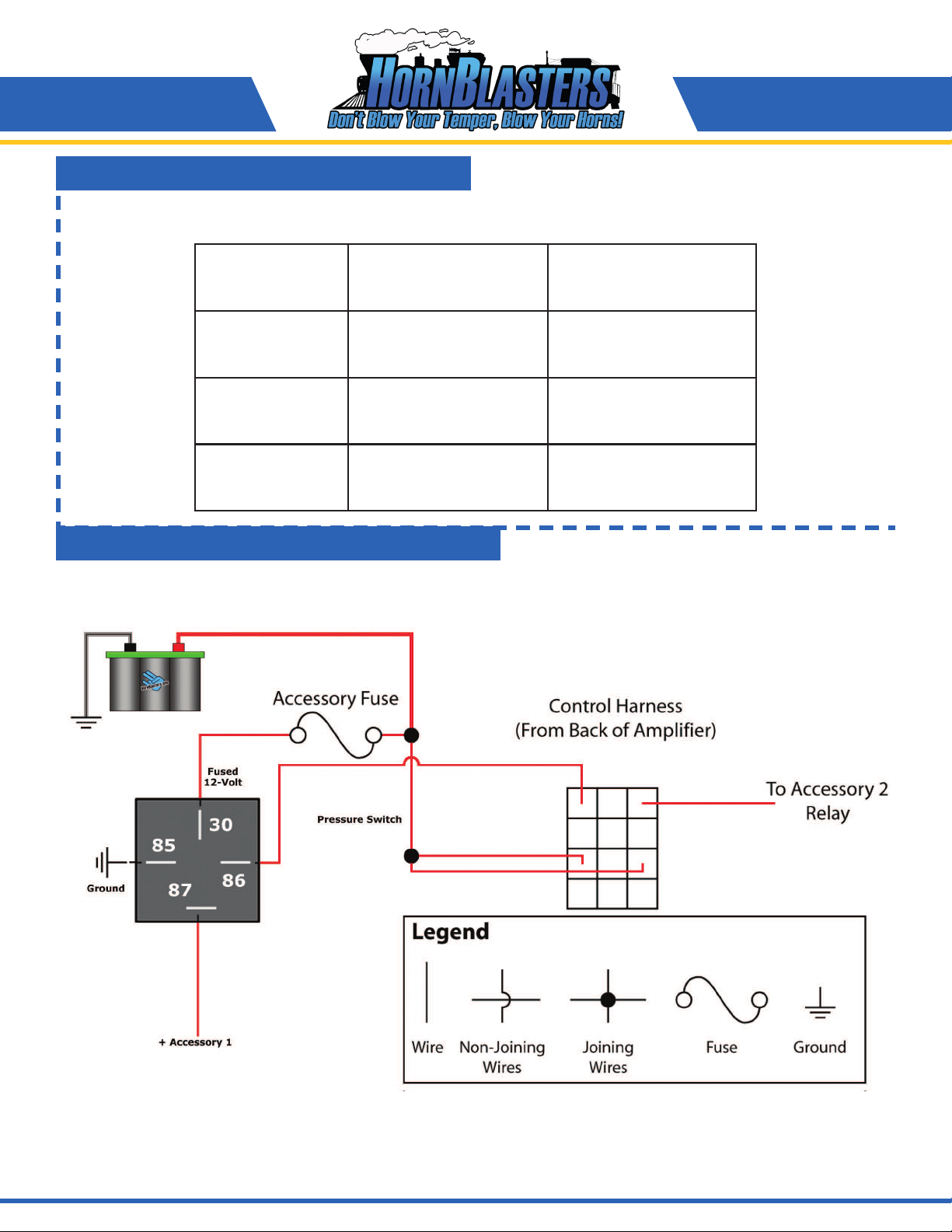
• In the wiring diagram on the following page, we have marked both inputs as positive for simplicity. In this model,
we would recommend wiring each accessory output to pin 85 on a separate relays. Then wire each relay pin 86 to
ground. You may then use pin 30 as a power source and 87 to connect to your device. On 5-pin relays, pin 97a is
active when your toggle switch is ‘o’ and pin 87 is when the toggle switch is ‘on’.
INSTALLING YOUR PUBLIC ADDRESS SYSTEM
IMPORTANT: We do not oer support on accessory switches and any accessories you attach to the PA
system. Opening the PA control unit will void your warranty with HornBlasters.

6511 N 54th St
Tampa, FL 33610
+1 (813) 783-8058
Fax: +1 (813) 783-2407
www.hornblasters.com [email protected]
• The control harness in the diagram is a representation of the harness at the back of the amplier.
• As shown in the legend, the thick (bolded) lines are ones required to use the public address/siren functions of the unit.
• The thinner lines, marked in the legend as optional connections, may be used to wire up accessories. Please refer to the
‘Accessory Switches’ section in the manual on page 2.
• Although the amplier contains 3 fuses (one for the input power, and one for each of the accessory switches) we recommend
installing an inline fuse from the battery. This will make the connections safer against re and also make maintenance easier.
• If your accessories will draw less than 8 amps each, you may use the diagram above. If your accessories pull more than 8 amps
then follow the wiring diagram on page 4.
• The speaker wires (green) may be reversed. This will reverse the speaker phase and should make no apparent dierence to
the listener. Ignore the fact that the speaker has red and black wires.
Having trouble? Call us today at 877.209.8179.
WIRING DIAGRAM IMPORTANT: Disconnect the ground (Negative -)
terminal from your battery until you are nished
making all electrical connections.

6511 N 54th St
Tampa, FL 33610
+1 (813) 783-8058
Fax: +1 (813) 783-2407
www.hornblasters.com [email protected]
The control harness comes pre-wired with the required wires to use the public address (bolded in diagram). To aid in understanding
the layout it is as follows: (use the red/black wires to determine orientation).
Having trouble? Call us today at 877.209.8179.
CLOSE UP ON THE CONTROL HARNESS
HIGH-AMP ACCESSORY WIRING DIAGRAM
Accessory 1 Output Power (+) (Red) Accessory 2 Output
(Not Used) Ground (-) (Black) (Not Used)
Accessory 1 Input (Not Used) Accessory 2 Input
Speaker Output A (Not Used) Speaker Output B

6511 N 54th St
Tampa, FL 33610
+1 (813) 783-8058
Fax: +1 (813) 783-2407
www.hornblasters.com [email protected]
TESTING YOUR INSTALLATION
Before using your public address and siren system, you should test the work you’ve done.
1. Make sure every electrical connection is solid and that there are no loose wires. A loose wire could create an electrical
re, blow a fuse, or cause other havoc in your vehicle.
2. Verify that the speaker and amplier are mounted securely. They must be able to withstand jerks, vibrations, and any
other shock that your vehicle exposes them too. If either does not feel secure, remount it and secure the unit safely before
continuing.
Read the usage instructions below carefully before using your public address system
USING YOUR PA-100H SYSTEM
Before using your Public Address & Siren system, please make sure you have read this entire instruction manual. Always make
sure that no person or animal is close to the system speaker when it is in use. You and anyone close to the device should always
use hearing protection. Failure to do so may lead to permanent injury. Use safety at all times.
USING YOUR PUBLIC ADDRESS SYSTEM
1. Turn the function dial to ‘radio’ on the front of your amplier.
2. Turn the gain up on your amplier (must be to an audible level)
3. Press and hold the button the side of the mic while speaking into it.
USING THE AIR HORN SOUND & SIRENS
You must be authorized to use the emergency sirens and sound eects. Please check with the local, state, and federal law
enforcement agencies before sounding a siren or using the air horn sound.
USING THE AIR HORN SOUND
The air horn sound is a distinctive emergency air horn tone. You may use this sound while the amplier is in any function mode.
1. Make sure the gain is turned up on your amplier (must be to an audible level).
2. Push up the air-horn/manual siren paddle to the air horn label. The amplier will play the sound as long as you hold the
paddle up.
USING THE AUTOMATIC SIRENS
The automatic siren functions will sound a siren repeatedly until the amplier is turned o or function dial is turned back to
‘radio’.
1. Make sure the gain is turned up on your amplier (must be to an audible level).
2. Turn the function dial to any of the siren options: Manual, Wail, Yelp, Yelp-1 or Hi-lo. Your amplier should begin to play
the selected siren automatically until it is turned o.
USING THE MANUAL SIREN
The manual siren may be used to override any of the automatic sirens, or while using the ‘radio’ function to play the siren for a
brief amount of time.
1. Make sure the gain is turned up on your amplier (must be to an audible level).
2. While using any of the functions, push the air horn/manual siren paddle down to the manual siren label. The amplier will
play the manual siren for a short period of time. You may interrupt it by turning your amplier o, pushing the talk button
on the mic (while in ‘radio’ function), or using the air horn sound eect momentarily.
Having trouble? Call us today at 877.209.8179.
Once you have nished your installation, make sure the gain of your amplier us turned to the ‘o’ position, the accessory switches
are in the o (0) positions, fuses are inserted into any fuse block you installed, and nally to reconnect the ground terminal of your
battery.
FINISHING UP

6511 N 54th St
Tampa, FL 33610
+1 (813) 783-8058
Fax: +1 (813) 783-2407
www.hornblasters.com [email protected]
GENERAL PUBLIC ADDRESS SYSTEM MAINTENANCE
• Make sure all wired connections are secure and making good contact.
• Periodically check to make sure that your speaker is free from dirt and debris.
TIPS
• Make sure your engine is running when your public address is in use to insure proper voltage proper
CAN’T FIGURE IT OUT?
No problem! Give us a call at 877-209-8179, or email at [email protected] and we’ll be more than happy to help you x
your system. Also feel free to visit our online train horn community, www.TrainHornForums.com, for more information.
No problem! Give us a call at 877-209-8179, or email at [email protected] and we’ll be more than happy to help you x
your system. Also feel free to visit our online train horn community, www.TrainHornForusm.com, for more information.
Having Trouble? Call us today! +1 (877) 209-8179
MAINTENANCE & TIPS
TROUBLESHOOTING
Problem Possible Cause(s) Correcve Acon
Public address system does
not turn on when gain is
turned up. (Light should light
up on control panel)
1. Fuse is blown.
2. Bad electrical connections.
3. Light has burnt out. (Unlikely)
1. Check all electrical connections. When okay,
replace fuse.
2. Make sure your negative and positive
connections are good.
3. Replace light and conrm the PA is receiving
power.
No sound is being output
from the speaker. (The
amplier is receiving power
and light turns on when gain
is turned up)
1. The gain turned up.
2. The speaker is not connected properly.
3. You are not using the mic correctly while on
the ‘radio’ function, and are not using a siren
function.
1. In order to hear anything from the speaker, the
gain must be turned up to an audible level.
2. Make sure one green wire is connected to the
black wire, and the other to the red wire. Make
sure the connections are good.
3. You must depress the mic button rmly while
speaking to produce sound. Otherwise, you may
turn the function dial to anything other than
‘radio’.
Accessory switches do not
do anything.
1. These switches only function if you add the
additional wiring circuits as described in the
wiring diagram. You have not made these
yet.
2. Blown fuse.
3. Bad electrical connections.
1. You may wire either a positive or negative
connection to the accessory input and then use
the output to provide power to your accessory.
(You do not have to wire both switches).
2. You must open your amplier and replace the
internal fuse.
3. Check connection with a multi-meter to insure
everything is hooked up correctly.
Table of contents
Popular Car Amplifier manuals by other brands

Audiosystem
Audiosystem R Series owner's manual

Sound Storm
Sound Storm Force F2.800 user guide

B2 Audio
B2 Audio Zero1 owner's manual

PowerAcoustik
PowerAcoustik Fanatik PF2.600 owner's manual

PowerAcoustik
PowerAcoustik PWR 180 instruction manual

Diamond Audio Technology
Diamond Audio Technology D7056 installation manual