Howden VARIAX B Service manual

Page 1 of 8
Technical Bulletin: Issue 3 – March 2014
Calibration of the Regulating Unit
on VARIAX®B & C Hub Fans
Internal and external
regulating parts –
schematic view
Howden has seen difficulties with the previous erection procedure for regulating
units on VARIAX®B & C Hub Fans. It is very important – especially for fans
operating in parallel – that the regulating units are mounted and calibrated correctly.
This procedure is implemented in all new erection and maintenance manuals edited after December 2013. The
procedure is valid for fans with Howden B- and C-hubs.
Verification Document V213351-9 (see pages 7/8/9).
3.20 Blade Pitch Actuator
The movement of the actuator lever is
transmitted to the external regulating arm of
the fan through a connecting rod. From the
external regulating arm the regulating
movements are transmitted to the hydraulic
regulating unit (hydraulic cylinder) through a
regulating shaft and a pull fork.
The position of the actuator in relation to the
regulating arm is designed so that the angular
motion of the actuator and the air volume are
almost linear.
1. The pedestal for the actuator on the
side of the diffuser has been mounted
according to the drawing in chapter
10.00 of the Fan Manuals “Actuator
Arrangement”. Verify the location of
the bracket is correct in verification
document V213351-9.
Figure 1: Bracket on outer regulating arm
Notice: All dimensions and angle given in this instruction are for reference only and the relevant project drawings must be
used when calibrating the regulating drive assembly.

Technical Bulletin
Page 2 of 8
2. Verify the regulating arm bracket (see
Figure 1) on the outer regulating arm
is at the correct radius according to the
drawing “Actuator Arrangement “
3. Check / adjust actuator crank length
“R1” (Figure 2) according to above
mentioned drawings.
4. Check measurements “L1” and “L2”
(Figure 2) according to the above
mentioned drawings – correct if
necessary. If tolerances are greater
than ± 3 mm (0.12”) contact Howden
for new calculation of “L3”.
5. Mount the rod ends on the external
regulating arm and adjust the
connecting rod length “L3 (Figure 2)
according to above mentioned
drawings.
6. Adjust the actuator until the bracket on
external regulating arm is in horizontal
position – see Figure 2. According to
above mentioned drawings.
Checkpoint: Check
measurement of the outer
regulating arrangement –
check horizontal position for
the bracket – see Calibration
of Regulating Drive Assembly
in verification document.
For electrical connections please see the
actual terminal plan in Fan Manuals.
3.21 Calibration of the Regulating
Drive Assembly (Internal and
External)
Adjustment of the regulating drive assembly
is very important to obtain an approximately
linear control of the blade pitch. This means
that the speed of the hydraulic cylinder is
constant. Regulating Drive geometry is
designed so that the torque from the actuator
cannot "break" the external regulating arm
(activating the torque switch) during normal
operation.
The theoretical minimum and maximum blade
angles can be found in the fan performance
curve (blade angles) in chapter 2.00 in Fan
Manuals. See example copy in Figure 3.
Checkpoint: Note actual
theoretical minimum blade
angle and actual maximum
blade angle in document
V213351-9.
Any blade angle (maximum/minimum)
references in section 3;00 of the IOM manual
must be verified by comparing the blade
angle on the fan performance curve in
chapter 2:00 of the IOM manual. Any
deviations may be reported to Howden for
clarification.
Figure 2: Extract from drawing “Actuator Arrangement”
Figure 3: Fan Curve – find actual curve in Fan Manual “Performance Data”
Min blade angle = lowest mentioned angle + 1: (here 30+1=31)
Max blade angle = highest mentioned working point +1: (here 77+1=78)

Technical Bulletin
Page 3 of 8
The procedure below describes how to adjust
the minimum and maximum mechanical
blade pitch regulating range of the fan
impeller, adjustment of the graduated scale at
the external regulating lever, and adjustment
of the torque switch mounted at the regulating
lever.
Check that the maximum allowable working
pressure has been reduced to an opening
pressure at app. 20-35 bar (290-507 psi). The
pressure reduction is required for mechanical
protection of the mechanical regulating parts
inside the hub when adjusting the mechanical
blade pitch range and the torque switch. See
chapter 3.00 in Fan Manuals “Mounting of Oil
Cabinets”
Warning: When handling
the blades, it is mandatory
to use Howden's hosting
tool for blades. See Figure 4
and Instruction Manual for
VARIAX®Blade Lifting Tool
in Fan Manual.
Close the ball valve placed in the pressure
line. Adjust the pressure relief valves at the
control oil pumps in the oil cabinet
downwards to the minimum pressure working
pressure, 20 bar (290 psi). Open the ball
valve and regulate the hub, if the hub does
not regulate, slow increase the pressure relief
valve setting until the hub moves.
Stop the Hydraulics and observe site safety
regulations for working on energized
equipment and fan blades.
1. Dismount one blade and mount the
blade adjustment tool onto the blade
pivot in the hub. See Figure 6.
(Note the blade pivot number at the
verification document V213351-9).
2. Start the control oil unit, for supplying
oil to the hydraulic regulating unit.
3. Verify the blade angle tool position, it
should be at 55˚. If adjustment is
required adjust the blade angle to 55°
(mid-pitch) on the blade angle tool by
loosening the set screws on the
internal crank and rotating the internal
crank manually. Exercise caution while
moving the blades.
4. Stop the control oil unit.
5. Check that the blade angle is 55°. If
necessary, start the control oil unit and
increase or decrease the blade angle
until 55° is reached when the control
oil unit is stopped.
6. Adjust the push rod length of the pull
fork when the blades are in the middle
position (55˚). The rod length should
be adjusted to position the internal
regulating crank arm exactly in the
vertical position.
Figure 4: Blade Lifting Tool
Figure 6: Blade Angle Measuring Tool
Figure 5: Nipple for Hydraulic Hoses
Figure 7: Regulating Unit
Figure 8: Blade “no touch distance”

Technical Bulletin
Page 4 of 8
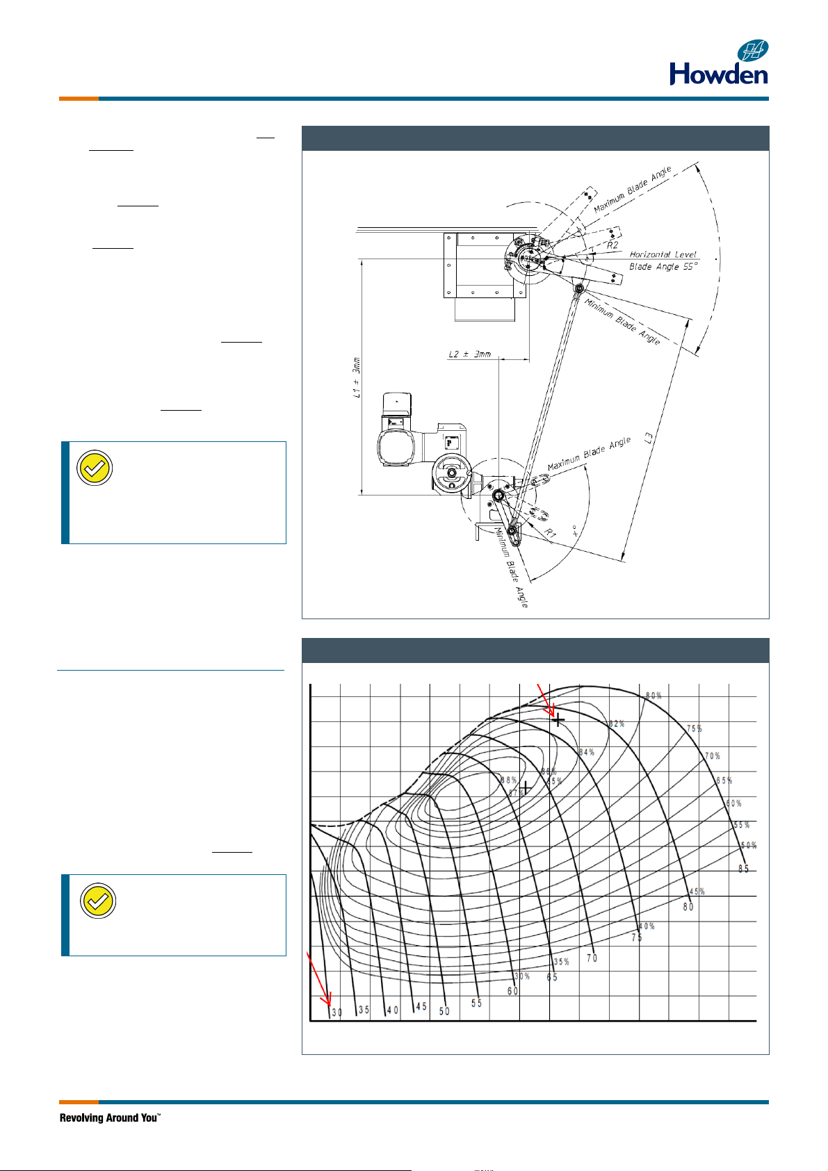
7. Start the control oil unit and check that
the blade angle is 55°. If necessary,
the pull fork push rod length may be
adjusted until the blade angle is 55°
with oil pressure.
8. Secure the crank in the vertical
position by means of the two socket
set screws.
Checkpoint: Check vertical
position for the crank arm –
see Calibration of Regulating
Drive Assembly in verification
document V213351-9.
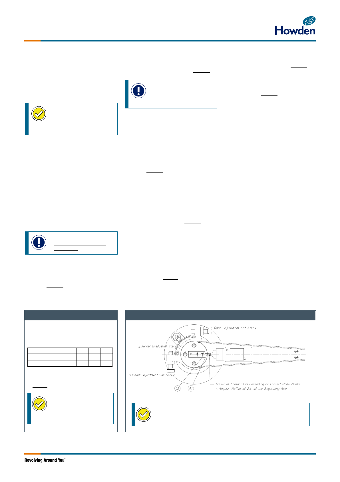
9. Adjust the regulating drive external
graduated scale to 55° ± 0.5°,
corresponding to 55° measured on the
graduated scale of the blade
adjustment tool. See Figure 9.
10. Start control oil unit.
11. Close the blades carefully to
mechanical minimum limit, a spike in
hydraulic pressure will indicate a hard
stop has been reached. Mechanical
minimum is: contact of the internal
parts in hub or blades are close to
touching each other. Record the angle
on the blade angle tool mounted in the
hub.
Notice: Important: Blades
are not allowed to touch
each other.
12. Then open blade angle 2°, measured
on the graduated scale of the blade-
angle adjustment tool, and tighten the
“closed mechanical stop bolt”
(see Figure 9) towards the stop pin.
13. To avoid mechanical contact between
the blades the current minimum blade
angle must be adjusted to a distance
between blades ≥3 mm – see Figure 8.
Notice: Correct example
blade angles in item 14) 19)
and 20) and Table 1
according to actual Fan Curve
14. Open the blades carefully to
mechanical maximum limit, a spike in
hydraulic pressure will indicate a hard
stop has been reached. Mechanical
maximum is: contact of the internal
parts in hub. Record the angle on the
blade angle tool mounted in the hub.
E.g. 78° measured on the graduated
scale of the blade adjustment tool and
tighten the “open mechanical stop bolt”
(see Figure 9) towards the stop pin.
15. Adjust blade angle to 55° measured at
the blade angle measuring tool and
check that external graduated scale
corresponds to 55° ± 0.5°.
16. Adjust the internal end of the travel
limit electronic switches and the
position feedback transmitter in the
actuator so that the “open and closed
mechanical stop bolts” (Figure 9) avoid
touching the stop pin in the extreme
position. One of the internal
mechanical switches can be adjusted
to the position corresponding to the fan
stall-cancelling angle.
17. The internal end of travel limit switches
in the actuator should be adjusted
according to the supplier's instructions.
18. When adjusted, the blade angles
(example) in Table 1 should be
reached. (recalculate mA value for stall
cancelling for actual blade angles).
19. Close the blades carefully to minimum
e.g. 31° and tighten the “closed
mechanical stop bolt” (see Figure 9)
slightly towards the stop pin and
secure with the locknut.
20. Open the blades to maximum e.g. 78°
and tighten the “open adjustment set
screw” (see Figure 9) slightly towards
the stop pin and secure with the
locknut.
21. Secure the internal crank and the
external regulating arm to the
regulating shaft by means of the socket
set screws. Dismount one screw at a
time and carefully drill a dimple (app 3
mm (0.12”)) in the shaft through the
threaded hole – take care not to
damage the thread. Carefully clean the
hole before remounting the screw.
22. Check that the friction brake disc and
friction disc are set at torque 10 Nm
(7.38 lbft) by adjusting the clearance
between the stop fork and the brake
disk to approx. 2-3 mm (0.08”-0.12”).
23. Mount the torque switch on the
external regulating arm (see drawing
no in Fan Manual) and adjust it
according to Figure 9. Adjust the screw
(01) so that the torque/limit switch is
activated, but still have a clearance of
X mm (Y”) to the bottom of the
torque/limit switch movement. Lock the
screw with the locknut (02).
24. Dismount the blade adjustment tool
and mount the blade.
25. Mount the inspection cover in the
impeller casing and seal with new
"Super Seal" (PTFE) packing cord.
26. If fans are installed for parallel
operation, the blade angle limits for
both fans should be adjusted to the
same value ± 0.5°.
Calculation of Set Point for Plant DCS
Figure 9: Placing of Torque Limit Switch
Correct angle according to curve from Fan
Performance Curve in the Fan Manual
Table 1 (reference only)
min blade angle 31 4,0 mA
max blade angle 78 20,0 mA
stall canceling angle ≤42 7,7 mA
Any deviations should be noted for further
programming of the DCS – refer specially
to item 14.
Checkpoint: Calibration
of Regulating Drive
Assembly in verification
document V213351-9 in
chapter 11.00.
Checkpoint:Readjust the pressure relief valves – note in Calibration
of Regulating Drive Assembly in verification document V213351-9.

Technical Bulletin
Page 5 of 8
Regulating Drive – Complete
3.22 Readjustment of Maximum
Working Pressure
1. Stop the control oil unit.
Warning: Depressurize
hoses/pipes containing high-
pressure fluids and allow them
to cool to a suitable temperature.
2. Dismount the supply and return oil
hoses at the rotating oil-seal and short-
circuit the two hoses with the nipple
used previously, see Figure 5.
3. Close the ball valve placed in the
pressure line just before the outlet
flange in the oil unit and start the oil unit.
Readjust the pressure relief valves at
the control oil pumps at the oil unit
upwards to the original pressure limit at
xxx bar (yyyy psi). Check actual value in
actual set point list in Fan Manual.
4. Stop the oil unit, dismount the short-
circuit valve and mount the supply and
return oil hoses at the rotating oil-seal.
3.23 Balancing the Counterweight
at the Internal Regulating
Crank Arm
All position numbers refer to drawing
“Regulating Drive – Complete” in Fan
Manual. See example above.
The internal regulating crank arm of the fan is
equipped with an adjustable counterweight
(30) mounted on a lever (29). The
counterweight is mounted to balance the
spring inside of the hydraulic cylinder, which
acts on the pilot valve, forcing it to go out of
position. If not balanced, hydraulic pressure
will result in an uncontrolled movement of the
hydraulic piston.
Adjustment of the counterweight balancing
the hydraulic pressure is done from the inside
of the inner tube of the diffuser. The external
regulating arm must be disconnected from
the actuator by disconnecting the connecting
rod from the external regulating arm.
Balance procedure:
1. Disconnect the external regulating
arm linkage.
2. Start the control oil unit.
3. Place the internal regulating crank
arm in a position approximately in
the middle of the regulating range.
4. Observe if the piston valve moves
and if so observe the direction.
5. If any movement is observed,
adjust the counterweight position
at the lever to increase the force
applied to the piston valve in the
opposite direction of the movement.
6. Repeat the adjustment procedure
by placing the internal regulating
crank arm in different positions,
including the end positions.
7. When adjusted stop the control oil
unit.
Checkpoint:Calibration of Regulating Drive Assembly in verification document V213351-9.

Technical Bulletin
Page 6 of 8
Howden Verification document V213351-9: Page 1

Technical Bulletin
Page 7 of 8
Howden Verification document V213351-9: Page 2

Technical Bulletin
For more information please contact your local Howden office.
This bulletin has been released by:
Howden Denmark ApS, Industrivej 23, DK-4700, Næstved, Denmark
Tel: +45 55 77 62 62
Web: www.howden.com
Email: [email protected]
Page 8 of
8
Howden Verification document V213351-9: Page 3
This manual suits for next models
1
Other Howden Fan manuals
Popular Fan manuals by other brands

S&P
S&P TPSB ECOWATT Series instruction manual

Bosch
Bosch DRC99PS25 User manual and installation instructions

Sonnenkonig
Sonnenkonig VIND 2 instruction manual

Fanimation
Fanimation KUTE 44 FPD8547BSBL manual

Commercial Electric
Commercial Electric BF24TFCE Use and care guide

Trion
Trion Grease Viper Series instructions

Ebmpapst
Ebmpapst R2E250-AS47-09 operating instructions

Ebmpapst
Ebmpapst R3G220-RD53-01 operating instructions

HAMPTON BAY
HAMPTON BAY SEAPORT AL634-WH Use and care guide

Gaggenau
Gaggenau AR 401 742 installation instructions

Ebmpapst
Ebmpapst R2E146-AW07-05 operating instructions

Bigassfans
Bigassfans Yellow Jacket installation guide