Howden Roots RAM Series Instruction manual

www.howden.com
RootsTM RAMTM and
RAM-J Series
Installation Operation & Maintenance Manual

2ISRB-2001 GEA20258 rev._04_16

3
ISRB-2001 GEA20258 rev._04_16
Information Summary....................................................1
Safety Precautions .......................................................3
Operating Limitations ....................................................3
Installation ............................................................... 4 - 6
Lubrication ..............................................................7, 13
Operation ......................................................................8
Contents
Troubleshooting.............................................................9
Inspection & Maintenance...........................................10
Figures .................................................................. 11-12
Tables..........................................................................13
Parts Lists ...................................................................14
Assembly Drawings.....................................................15
o Check shipment for damage. If found, file claim with
carrier and notify Howden.
o Unpack shipment carefully, and check contents against
Packing List. Notify Howden if a shortage appears.
o Store in a clean, dry location until ready for
installation. Lift by methods discussed under
INSTALLATION to avoid straining or distorting the equip-
ment. Keep covers on all openings. Protect against weather
and corrosion if outdoor storage
is necessary.
o Read OPERATING LIMITATIONS and INSTALLATION
sections in this manual and plan the complete
installation.
o Provide for adequate safeguards against accidents
to persons working on or near the equipment during both
installation and operation. See SAFETY
PRECAUTIONS.
o Install all equipment correctly. Foundation design must be
adequate and piping carefully done. Use recommended
accessories for operating protection.
Do these things to get the most from your Roots Blower
Roots products are sold subject to Howden’s general terms of sale and warranty policy; contact your nearest
Howden office for more information.
o Make sure both driving and driven equipment is
correctly lubricated before start-up. See
LUBRICATION.
o In event of trouble during installation or operation, do
not attempt repairs of Howden furnished equipment. Notify
Howden, giving all nameplate information plus an outline of
operating conditions and a description of the trouble. Un-
authorized attempts at equipment repair may void Howden
warranty.
o Units out of warranty may be repaired or adjusted
by the owner. Good inspection and maintenance
practices should reduce the need for repairs.
NOTE: Information in this manual is correct as of the
date of publication. Howden reserves the right to make design
or material changes without notice, and without
obligation to make similar changes on equipment of
prior manufacture.

4ISRB-2001 GEA20258 rev._04_16
Operating Limitations
A Roots blower or exhauster must be operated within certain
approved limiting conditions to enable continued satisfactory
performance. Warranty is contingent on such operation.
Maximum limits for pressure, temperature and speed are speci-
fied in Table 1, page 13 for various models & sizes of blowers
& exhausters. These limits apply to all units of normal construc-
tion, when operated under standard atmospheric conditions.
Be sure to arrange connections or taps for instruments such as
thermometers and pressure or vacuum gauges at or near the
inlet and discharge connections of the unit. These, along with a
tachometer, will enable periodic checks of operating conditions.
Pressure – The pressure rise, between inlet and discharge,
must not exceed the figure listed for the specific unit frame
size concerned. Also, in any system where the unit inlet is at a
positive pressure above atmosphere a maximum case rating
of 25 PSI gauge (1725 mbar) should not be exceeded without
first consulting Roots. Never should the maximum allowable
differential pressure be exceeded.
On vacuum service, with the discharge to atmospheric pres-
sure, the inlet suction or vacuum must not be greater than
values listed for the specific frame size.
Temperature – Blower & exhauster frame sizes are approved
only for installations where the following temperature limitations
can be maintained in service:
• Measured temperature rise must not exceed listed values
when the inlet is at ambient temperature. Ambient is con-
sidered as the general temperature of the space around
the unit. This is not outdoor temperature unless the unit is
installed outdoors.
• If inlet temperature is higher than ambient, the listed allow-
able temperature rise values must be reduced by 2/3 of
the difference between the actual measured inlet tempera-
ture and the ambient temperature.
• The average of the inlet and discharge temperature must
not exceed 250°F. (121°C).
• The ambient temperature of the space the blower/motor is
installed in should not be higher than 120°F (48.8°C).
Speed – These blowers & exhausters may be operated at
speeds up to the maximum listed for the various frame sizes.
They may be direct coupled to suitable constant speed drivers
if pressure/temperature conditions are also within limits. At low
speeds, excessive temperature rise may be a limiting factor.
Special Note: The listed maximum allowable temperature rise
for any particular blower & exhauster may occur well before
its maximum pressure or vacuum rating is reached. This may
occur at high altitude, low vacuum or at very low speed. The
units’ operating limit is always determined by the maximum
rating reached first. It can be any one of the three: Pressure,
Temperature or Speed.
Safety Precautions
It is important that all personnel observe safety
precautions to minimize the chances of injury.
Among many considerations, the following should be particu-
larly noted:
• Blower casing and associated piping or accessories
may become hot enough to cause major skin burns on
contact.
• Internal and external rotating parts of the blower and
driving equipment can produce serious physical injuries.
Do not reach into any opening in the blower while it is
operating, or while subject to accidental starting. Protect
external moving parts with adequate guards.
• Disconnect power before doing any work, and avoid
bypassing or rendering inoperative any safety or
protective devices.
• If blower is operated with piping disconnected, place a
strong coarse screen over the inlet and avoid standing in
the discharge air stream.
CAUTION: Never cover the blower inlet with your hand or
other part of body.
• Stay clear of inlet and discharge openings.
• Stay clear of the blast from pressure relief valves and the
suction area of vacuum relief valves.
• Use proper care and good procedures in handling,
lifting, installing, operating and maintaining the
equipment.
• Casing pressure must not exceed 25 psi (1725 mbar)
gauge. Do not pressurize vented cavities from an external
source, nor restrict the vents without first consulting
Howden.
• Do not use air blowers on explosive or hazardous gases.
• Other potential hazards to safety may also be
associated with operation of this equipment.
All personnel working in or passing through the area
should be trained to exercise adequate general safety
precautions.

5
ISRB-2001 GEA20258 rev._04_16
Installation
Howden blowers & exhausters are treated after factory assembly
to protect against normal atmospheric corrosion. The maximum
period of internal protection is considered to be one year under
average conditions, if shipping plugs & seals are not removed.
Protection against chemical or salt water
atmosphere is not provided. Avoid opening the unit until ready to
start installation, as corrosion protection will be quickly lost due
to evaporation.
If there is to be an extended period between installation
and start up, the following steps should be taken to ensure
corrosion protection.
o Coat internals of cylinder, gearbox and drive end bearing
reservoir with Nox-Rust VCI-10 or equivalent. Repeat once a
year or as conditions may require. Nox-Rust
VCI-10 is petroleum soluble and does not have to be re-
moved before lubricating. It may be obtained from Daubert
Chemical Co., 2000 Spring Rd., Oak Brook, Ill. 60521.
o Paint shaft extension, inlet and discharge flanges, and
all other exposed surfaces with Nox-Rust X-110 or equiva-
lent.
o Seal inlet, discharge, and vent openings. It is not recom-
mended that the unit be set in place, piped to the system,
and allowed to remain idle for extended periods. If any part is
left open to the atmosphere, the Nox-Rust VCI-10 vapor will
escape and lose its effectiveness.
o Protect units from excessive vibration during storage.
o Rotate shaft three or four revolutions every two weeks.
o Prior to start up, remove flange covers on both inlet and
discharge and inspect internals to ensure absence of rust.
Check all internal clearances.
Because of the completely enclosed unit design, location of
the installation is generally not a critical matter. A clean, dry and
protected indoor location is preferred. However, an
outdoor location will normally give satisfactory service.
Important requirements are that the correct grade of lubricating
oil be provided for expected operating temperatures, and that
the unit be located so that routine checking and servicing can
be performed conveniently. Proper care in locating driver and
accessory equipment must also be considered.
Supervision of the installation by a Howden Service Engineer is
not usually required for these units. Workmen with experience
in installing light to medium weight machinery should be able to
produce satisfactory results. Handling of the equipment needs
to be accomplished with care, and in compliance with safe
practices. Unit mounting must be solid, without strain or twist,
and air piping must be clean, accurately aligned and properly
connected.
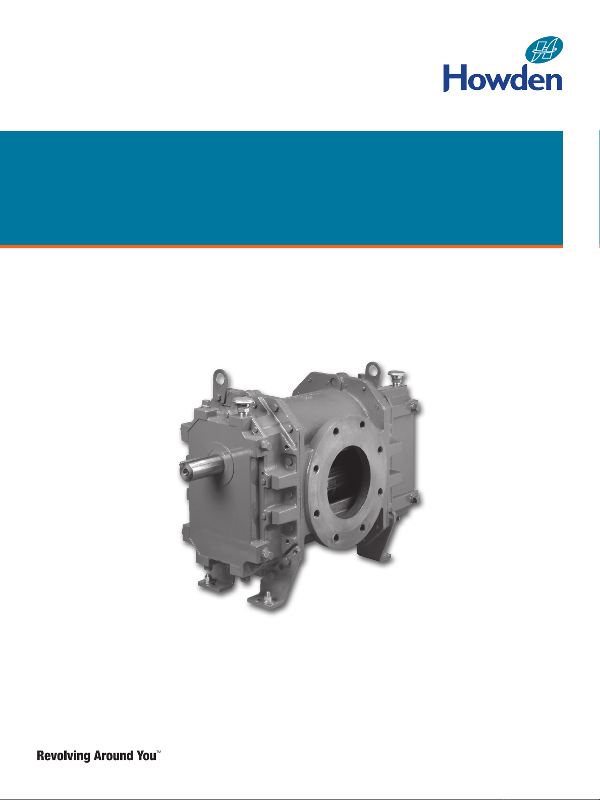
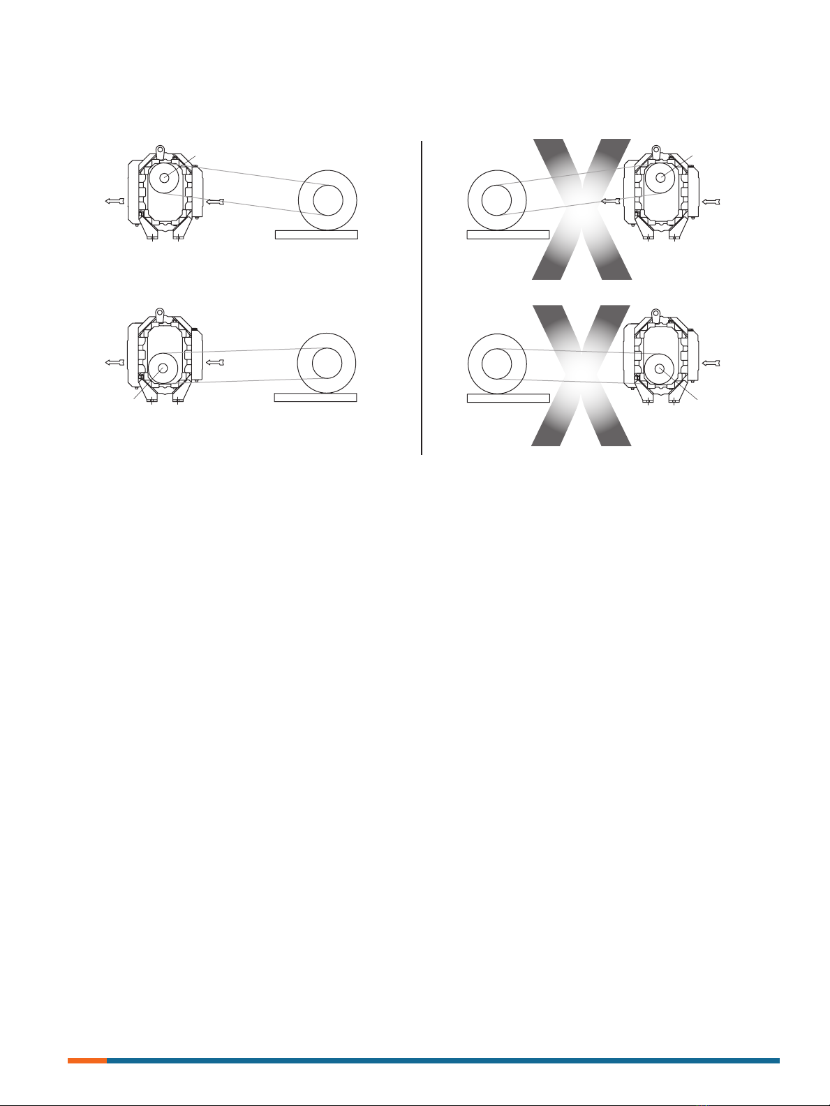
Bare-shaft Units: Two methods are used to handle a unit
without base. One is to use lifting lugs bolted into the top of the
unit headplates. Test them first for tightness and fractures by
tapping with a hammer. In lifting, keep the direction of cable
pull on these bolts as nearly vertical as possible. If lifting lugs
are not available, lifting slings may be passed under the cylinder
adjacent to the headplates. Either method prevents strain on the
extended drive shaft.
Packaged Units: When the unit is furnished mounted on
a baseplate, with or without a driver, use of lifting slings passing
under the base flanges is required. Arrange these slings so that
no strains are placed on the unit casing or mounting feet, or
on any mounted accessory equipment. DO NOT use the lifting
lugs in the top of the unit headplates.
Before starting the installation, remove plugs, covers or seals
from unit inlet and discharge connections and inspect the
interior completely for foreign material. If cleaning is required,
finish by washing the cylinder, headplates and impeller thor-
oughly with a petroleum solvent. Turn the drive shaft by hand
to make sure that the impellers turn freely at all points. Anti-rust
compound on the connection flanges and drive shaft extension
may also be removed at this time with the same solvent. Cover
the flanges until ready to
connect piping.
Mounting
Care will pay dividends when arranging the unit mounting. This
is especially true when the unit is a “bare-shaft” unit furnished
without a baseplate. The convenient procedure may be to
mount such a unit directly on a floor or small concrete pad,
but this generally produces the least satisfactory results. It
definitely causes the most problems in leveling and alignment
and may result in a “Soft Foot” condition. Correct soft foot be-
fore operation to avoid unnecessary loading on the casing and
bearings. Direct use of building structural framing members is
not recommended.
For blowers without a base, it is recommended that a well
anchored and carefully leveled steel or cast iron mounting plate
be provided. The plate should be at least 1 inch (25 mm) thick,
with its top surface machined flat, and large enough to provide
leveling areas at one side and one end after the unit is mount-
ed. It should have properly sized studs or tapped holes located
to match the unit foot drilling. Proper use of a high quality
machinist’s level is necessary for adequate installation.
With the mounting plate in place and leveled, set the unit
on it without bolting and check for rocking. If it is not solid,
determine the total thickness of shims required under one foot
to stop rocking. Place half of this under each of the diagonally-
opposite short feet, and tighten the mounting studs or screws.
Rotate the drive shaft to make sure the impellers turn freely. If
the unit is to be direct coupled to a driving motor, consider the
height of the motor shaft and
the necessity for it to be aligned very accurately with the unit
shaft. Best unit arrangement is directly bolted to the mount-
ing plate while the driver is on shims of at least 1/8 inch (3mm)
thickness. This allows adjustment of motor position in final
shaft alignment by varying the shim thickness.
Aligning
When unit and driver are factory mounted on a common base-
plate, the assembly will have been properly aligned and is to be
treated as a unit for leveling purposes. Satisfactory installation
can be obtained by setting the baseplate on a concrete slab
that is rigid and free of vibration, and leveling the top of the
base carefully in two directions so that it is free of twist. The
slab must be provided with suitable anchor bolts. The use of
grouting under and partly inside the leveled and shimmed base
is recommended.

6ISRB-2001 GEA20258 rev._04_16
It is possible for a base-mounted assembly to become twisted
during shipment, thus disturbing the original
alignment. For this reason, make the following checks after
the base has been leveled and bolted down. Disconnect the
drive and rotate the unit shaft by hand. It should turn freely at all
points. Loosen the unit foot hold-down screws and
determine whether all feet are evenly in contact with the base. If
not, insert shims as required and again check for free impel-
ler rotation. Finally, if unit is direct coupled to the driver, check
shaft and coupling alignment carefully and make any necessary
corrections.
In planning the installation, and before setting the unit,
consider how piping arrangements are dictated by the unit
design and assembly. Drive shaft rotation must be established
accordingly and is indicated by an arrow near the shaft.
Typical arrangement on vertical units has the drive shaft at the
top with counterclockwise rotation and discharge to the left.
Horizontal units are typically arranged with the drive shaft at the
left with counterclockwise rotation and discharge down. See
Figure 4 for other various unit
arrangements and possible conversions.
When a unit is DIRECT COUPLED to its driver, the driver
RPM must be selected or governed so as not to exceed the
maximum speed rating of the unit. Refer to Table 1, page 13 for
allowable speeds of various unit sizes.
A flexible type coupling should always be used to connect the
driver and unit shafts.
When direct coupling a motor or engine to a blower you
must ensure there is sufficient gap between the coupling halves
and the element to prevent thrust loading the blower bearings.
When a motor, engine or blower is operated the shafts may
expand axially. If the coupling is installed in such a manner that
there is not enough room for expansion the blower shaft can be
forced back into the blower and cause the impeller to contact the
gear end headplate resulting in damage to the blower. The two
shafts must be in as near
perfect alignment in all directions as possible, and the gap must
be established with the motor armature on its
electrical center if end-play exists. Coupling manufacturer’s rec-
ommendations for maximum misalignment, although
acceptable for the coupling, are normally too large to
achieve smooth operation and maximum life of the blower.
The following requirements of a good installation are
recommended. When selecting a coupling to be fitted to the
blower shaft Roots recommends a taper lock style coupling to
ensure proper contact with the blower shaft. Coupling halves
must be fitted to the two shafts with a line to line thru .001” inter-
ference fit. Coupling halves must be warmed up per
coupling manufacturer’s recommendations. Maximum
deviation in offset alignment of the shafts should not exceed .005”
(.13 mm) total indicator reading, taken on the two
coupling hubs. Maximum deviation from parallel of the inside
coupling faces should not exceed .001” (.03 mm)
when checked at six points around the coupling.
When a unit is BELT DRIVEN, the proper selection of sheave
diameters will result in the required unit speed. When selecting
a sheave to be fitted to the blower shaft Roots recommends a
taper lock style sheave to ensure proper
contact with the blower shaft. This flexibility can lead to operat-
ing temperature problems caused by unit speed being too
low. Make sure the drive speed selected is within the allowable
range for the specific unit size, as specified under Table 1,
page 13.
Belt drive arrangements should employ two or more V-belts
running in grooved sheaves. Installation of the driver is less
critical than for direct coupling, but its shaft must be level and
parallel with the unit shaft. The driver should be mounted
on the inlet side of a vertical unit (horizontal piping)
and on the side nearest to the shaft on a
horizontal unit. The driver must also be mounted on an
adjustable base to permit installing, adjusting and removing
the V-belts. To position the driver correctly, both sheaves need
to be mounted on their shafts and the nominal shaft center
distance known for the belt lengths to be used.
CAUTION: Drive couplings and sheaves (pulleys) should have
an interference fit to the shaft of the blower (set screw types
of attachment generally do not provide reliable service.) It is
recommended that the drive coupling or sheave used have a
taper lock style bushing which is properly sized to provide the
correct interference fit required. Drive couplings, that require
heating to fit on the blower shaft, should be installed per cou-
pling manufacturer recommendations. A drive
coupling or sheave should not be forced on to the shaft of the
blower as this could affect internal clearances resulting in dam-
age to the blower.
Engine drive applications often require special
consideration to drive coupling selection to avoid
harmful torsional vibrations. These vibrations may
lead to blower damage if not dampened adequately.
It is often necessary to install a fly-wheel and/or a
torsionally soft elastic element coupling based on the
Engine manufacturer recommendations.
The driver sheave should also be mounted as close to its
bearing as possible, and again should fit the shaft correctly.
Position the driver on its adjustable base so that 2/3 of the total
movement is available in the direction away from the unit, and
mount the assembly so that the face of the sheave is accu-
rately in line with the unit sheave. This position
minimizes belt wear, and allows sufficient adjustment for both
installing and tightening the belts. After belts are
installed, adjust their tension in accordance with the
manufacturer’s instructions. However, only enough
tension should be applied to prevent slippage when the
unit is operating under load. Excessive tightening can
lead to early bearing concerns or shaft breakage.
Before operating the drive under power to check initial belt ten-
sion, first remove covers from the unit connections. Make sure
the interior is still clean, then rotate the shaft by hand. Place
a coarse screen over the inlet connection to prevent anything
being drawn into the unit while it is operating, and avoid stand-
ing in line with the discharge opening. Put oil in the sumps per
instructions under LUBRICATION.

7
ISRB-2001 GEA20258 rev._04_16
Motor on Inlet Side of Blower (Top Shaft)
Motor on Inlet Side of Blower (Bottom Shaft)
Bottom Shaft
INLETDISCHARGE
Top Shaft
DISCHARGEINLET
Motor on Drive Shaft
Side of Blower
INLET
DISCHARGE
Drive Shaft Driven Shaft
Motor on Discharge Side of Blower (Top Shaft)
INLET
DISCHARGE
Top Shaft
Motor on Discharge Side of Blower (Bottom Shaft)
Bottom Shaft
INLET
DISCHARGE
Motor on Driven Shaft
Side of Blower
INLET
DISCHARGE
Drive Shaft Driven Shaft
Acceptable Blower Drive Arrangement Options
ACCEPTABLE UNACCEPTABLE
Piping
Before connecting piping, remove any remaining anti-rust com-
pound from Unit connections. Clean pipe should be no smaller
than unit connections. In addition, make sure it is free of scale,
cuttings, weld beads, or foreign material of any kind. To further
guard against damage to the unit,
especially when an inlet filter is not used, install a substantial
screen of 16 mesh backed with hardware cloth at or near
the inlet connections. Make provisions to clean this screen of
collected debris after a few hours of operation. It should be re-
moved when its usefulness has ended, as the wire will eventu-
ally deteriorate and small pieces going into the unit may cause
serious damage.
Pipe flanges or male threads must meet the unit connections
accurately and squarely. DO NOT attempt to correct misalign-
ment by springing or cramping the pipe. In most cases this will
distort the unit casing and cause impeller rubbing. In severe
cases it can prevent operation or result
in a broken drive shaft. For similar reasons, piping should
be supported near the unit to eliminate dead weight strains.
Also, if pipe expansion is likely to occur from temperature
change, installation of flexible connectors or expansion joints is
advisable.
Figure 3, page 11 represents an installation with all
accessory items that might be required under various
operating conditions. Inlet piping should be completely free of
valves or other restrictions. When a shut-off valve can not be
avoided, make sure a full size vacuum relief is installed nearest
the unit inlet. This will help protect
against unit overload caused by accidental closing of
the shut-off valve.
Need for an inlet silencer will depend on unit speed and pres-
sure, as well as sound-level requirements in the general sur-
roundings. An inlet filter is recommended, especially in
dusty or sandy locations. A discharge silencer is also normally
suggested, even though WHISPAIR™units operate at generally
lower noise levels than conventional rotary blowers. Specific
recommendations on silencing can be obtained from your local
Roots distributor.
Discharge piping requires a pressure relief valve, and should
include a manual unloading valve to permit starting the unit un-
der no-load conditions. Reliable pressure/vacuum gauges and
good thermometers at both inlet and discharge are recom-
mended to allow making the important checks on unit operat-
ing conditions. The back-pressure regulator shown in Figure 3,
page 11 is useful mainly when volume demands vary while the
unit operates at constant output. If demand is constant, but
somewhat lower than the unit output, excess may be blown off
through the manual unloading valve.
In multiple unit installations where two or more units
operate with a common header, use of check valves
is mandatory. These should be of a direct acting or free
swinging type, with one valve located in each line between the
unit and header. Properly installed, they will protect against
damage from reverse rotation caused by air and material back-
flow through an idle unit.
After piping is completed, and before applying power, rotate
the drive shaft by hand again. If it does not move with uniform
freedom, look for uneven mounting, piping strain, excessive
belt tension or coupling misalignment.
DO NOT operate the unit at this time unless it has been lubri-
cated per instructions.

8ISRB-2001 GEA20258 rev._04_16
Lubrication
Due to sludge build-up and seal leakage problems,
Roots recommendation is DO NOT USE Mobil SHC
synthetic oils in Roots blowers.
LUBRICATION: For Units with Splash Lubrication on
Both Ends.
• The specified and recommended oil is Roots Synthetic oil
of correct viscosity per Table 2, page 13.
• The proper oil level should be half way or middle of the
sight gauge when the blower is not operating. DO NOT
OVERFILL OIL SUMP/S as damage to the blower may
occur.
• Oil level may rise or fall in the gauge during operation to an
extent depending somewhat on oil temperature and blower
speed.
• It is recommended that the oil be changed after initial 100
hours of operation.
• Proper service intervals of the oil thereafter are based on
the discharge air temperature of the blower. Please refer to
the information below to properly determine the oil service
intervals.
• If you choose to use another oil other than the specified
and recommended Roots Synthetic, use a good grade of
industrial type non-detergent, rust inhibiting,
anti-foaming oil and of correct viscosity per Table 2, page
13.
• Roots does NOT recommend the use of automotive type
lubricants, as they are not formulated with the properties
mentioned above.
Normal life expectancy of the specified and recommended
Roots Synthetic oil is approximately 6000 hours with an oil
temperature of 180°F (82°C) or less. As the oil temperature
increases by increments of 15°F (8°C), the oil life is reduced by
half for each 15°F (8°C) increase. Example: Oil temperatures of
195°F (90.5°C) will produce a life expectancy reduced by half or
3000 hours oil service life.
Normal life expectancy of petroleum based oils is about 2000
hours with an oil temperature of about 180°F (82°C). As the oil
temperature increases by increments of 15°F (8°C), the life is
reduced by half for each 15°F (8°C) increase. Example: Oil tem-
peratures of 195°F (90.5°C) will produce life expectancy reduced
by half or 1000 hours oil service life.
NOTE: To estimate oil temperature, multiply the
discharge temperature of the blower by 0.80. Example: if the
discharge air temperature of the blower is 200° F, it is estimated
that the oil temperature is 160° F.
Bearings and oil seals are lubricated by the action of the timing
gears or oil slingers which dip into the main oil sumps caus-
ing oil to splash directly on gears and into bearings and seals.
A drain port is provided below each bearing to prevent an
excessive amount of oil in the bearings. Seals located inboard
of the bearings in each headplate effectively retain oil within
the sumps. Any small leakage that may occur should the seals
wear passes into a cavity in each vented headplate and is
drained downward. Oil sumps on each end of the blower are
filled by removing top vent plugs, Item (21), and filling until oil
reaches the middle of the oil level sight gauge, Item (37).
Initial filling of the sumps should be accomplished with the
blower not operating, in order to obtain the correct oil level. Ap-
proximate oil quantities required for blowers of the
various models and configurations are listed in Table 3, page
13.
The oil level should not fall below the middle of the site gauge
when the blower is idle.
Proper lubrication is usually the most important single
consideration in obtaining maximum service life and
satisfactory operation from the unit. Unless operating
conditions are severe, a weekly check of oil level and
necessary addition of lubricant should be sufficient. During the
first week of operation, check the oil levels in the oil sumps
about once a day, and watch for leaks. Replenish as necessary.
Thereafter, an occasional check should be sufficient.
More frequent oil service may be necessary if the blower is
operated in a very dusty location.
Roots Synthetic oil is superior in performance to petroleum
based products. It has high oxidation stability, excellent corro-
sion protection, extremely high film strength and low coefficient
of friction. Typical oil change intervals are increased 2-3 times
over petroleum based lubricants. Also, Roots Synthetic oil is
100% compatible with petroleum based oils. Simply drain the
oil in the blower and refill the reservoirs with Roots Synthetic oil
to maintain optimum performance of your Roots blower.

9
ISRB-2001 GEA20258 rev._04_16
Operation
Before operating a blower under power for the first time,
recheck the unit and the installation thoroughly to reduce the
likelihood of avoidable troubles. Use the following procedure
check list as a guide, but consider any other special conditions
in the installation.
o Be certain that no bolts, tools, rags, or debris have been
left in the blower air chamber or piping.
o If an outdoor intake without filter is used, be sure the open-
ing is located so it cannot pick up dirt and is protected by
a strong screen or grille. Use of the temporary protective
screen as described under INSTALLATION is strongly rec-
ommended.
o Recheck blower leveling, drive alignment and tightness of
all mounting bolts if installation is not recent. If belt drive is
used, adjust belt tension correctly.
o Turn drive shaft by hand to make sure impellers still rotate
without bumping or rubbing at any point.
o Ensure oil levels in the main oil sumps are correct.
o Check lubrication of driver. If it is an electric motor, be sure
that power is available and that electrical overload devices
are installed and workable.
o Open the manual unloading valve in the discharge air line. If
a valve is in the inlet piping, be sure it is open.
o Bump blower a few revolutions with driver to check that
direction of rotation agrees with arrow near blower shaft,
and that both coast freely to a stop.
After the preceding points are cleared, blower is ready for trial
operation under “no-load” conditions. The following procedure
is suggested to cover this initial operation test period.
a. Start blower, let it accelerate to full speed, then shut off.
Listen for knocking sounds, both with power on and as
speed slows down.
b. After blower comes to a complete stop, repeat above, but
let blower run 2 or 3 minutes. Check for noises, such as
knocking sounds.
c. After blower comes to a complete stop, operate
blower for about 10 minutes unloaded. Check oil levels.
Observe cylinder and headplate surfaces for
development of hot spots such as burned paint, indicat-
ing impeller rubs. Be aware of any noticeable increase in
vibration.
Assuming that all trials have been satisfactory, or that
necessary corrections have been made, the blower should
now have a final check run of at least one hour under
normal operating conditions. After blower is restarted,
gradually close the discharge unloading valve to apply working
pressure. At this point it is recommended that
a pressure gauge or manometer be connected into the
discharge line if not already provided, and that
thermometers be in both inlet and discharge lines.
Readings from these instruments will show whether
pressure or temperature ratings of the blower are
being exceeded.
During the final run, check operating conditions frequently
and observe the oil levels at reasonable intervals. If excessive
noise or local heating develops, shut down immediately and
determine the cause. If either pressure rise or temperature rise
across the blower exceeds the limit specified in this manual,
shut down and investigate conditions in the piping system.
Refer to the TROUBLESHOOTING CHECKLIST for sug-
gestions on various problems that may appear.
The blower should now be ready for continuous duty
operation at full load. During the first few days make periodic
checks to determine whether all conditions remain steady, or
at least acceptable. This may be particularly important if the
blower is supplying air to a process system where conditions
can vary. At the first opportunity, stop the blower and clean the
temporary inlet protective screen.
If no appreciable amount of debris has collected, the
screen may be removed.
See comments under INSTALLATION. At this same time,
verify leveling, coupling alignment or belt tension, and mounting
bolt tightness.
Should operating experience prove that blower capacity is
a little too high for the actual air requirements, a small excess
may be blown off continuously through the
manual unloading or vent valve. Never rely on the pressure
relief valve as an automatic vent. Such use may cause the
discharge pressure to become excessive, and can also
result in unsafe operation of the valve itself. If blower
capacity appears to be too low, refer to the
TROUBLESHOOTING CHECKLIST.
Vibration Assessment Criteria
With measurements taken at the bearing locations on the
housings, see chart below for an appropriate assessment
guide for rotary lobe blowers rigidly mounted on
stiff foundations.
In general, blower vibration levels should be monitored on a
regular basis and the vibration trend observed for progressive
or sudden change in level. If such a change occurs, the cause
should be determined through spectral analysis.
As shown on the chart below, the level of all pass vibration will
determine the need to measure discrete frequency vibration
levels and the action required.
All Pass Vibra-
tions
(in/sec)
Discrete Fre-
quency
Vibration (in/
sec)
Action
0.45 or less N/R Acceptable
Greater than
0.45 but 1.0 or
less
0.45 or less @
any frequency
Greater than
0.45 @ any fre-
quency
Acceptable
Investigate
Greater than
1.0
Less than 1.0
Greater than 1.0
Investigate
Investigate

10 ISRB-2001 GEA20258 rev._04_16
Troubleshooting Checklist
Trouble Item Possible Cause Remedy
No flow 1
2
3
Speed too low
Wrong rotation
Obstruction in pip-
ing
Check by tachometer and compare with published performance.
Compare actual rotation with Figure 1, change driver if wrong.
Check piping, valves, silencer to assure open flow path.
Low capacity 4
5
6
7
Speed too low
Excessive pressure
rise
Obstruction in pip-
ing
Excessive slip
See item 1, if belt drive, check for slippage and readjust tension.
Check inlet vacuum and discharge pressure and compare with
published performance.
See item 3.
Check inside of casing for worn or eroded surfaces causing
excessive clearances
Excessive power 8
9
10
11
Speed too high
Excessive pressure
rise
Impeller rubbing
Scale , sludge, rust
or product build up
Check speed and compare with published performance.
See item 5
Inspect outside of cylinder for high temperature areas, then
check for impeller contact at these points. Correct blower
mounting, drive alignment.
Clean blower appropriately
Damage to bearings
or gears
12
13
14
15
16
Inadequate lubrica-
tion
Excessive lubrica-
tion
Excessive pressure
rise
Coupling misalign-
ment
Excessive belt ten-
sion
Check oil sump levels in gear and drive end headplates
Check oil levels. If correct, drain and refill with clean oil of
recommended grade.
See item 5.
Check carefully. Realign if questionable.
Readjust for correct tension.
Vibration 17
18
19
20
21
22
23
24
Misalignment
Impellers rubbing
Worn bearings/
gears
Unbalanced or rub-
bing impeller
Driver or blower
loose
Piping resonances
Scale/sludge build-
ups
Casing strain
See item 15
See item 10
Check gear backlash and conditions of bearings and replace as
indicated.
Scale or process material may build up on casing and impellers, or
inside impellers. Remove build-up to restore original clearances and
impeller balance.
Tighten mounting bolts securely.
Determine whether standing wave pressure pulsations are present in
the piping.
Clean out interior of impeller lobes to restore dynamic balance.
Re-work piping alignment to remove excess strain.
Driver stops, or will
not start
25
26
Impeller stuck
Scale, sludge, rust
or product build-up
Check for excessive hot spot on headplate or cylinder. See item
10. Look for defective shaft bearing and/or gear teeth.
Clean blower appropriately
Excessive breather
Blow-by or excessive
oil leakage to vent
area
Excessive oil leakage
in vent area
27
28
29
30
31
32
Broken seal
Defective O-ring
Defective/plugged
breather
Oil level too high
Oil type or viscosity
incorrect
Blower running hot
Replace seals
Replace seals and O-ring
Replace breather and monitor oil leakage
Check sump levels in gear and drive headplates
Check oil to ensure it meets recommendations. Drain then fill
with clean oil of recommended grade.
Recommended oil temperature can be found on page 6 of this
manual. The blower must be operated within the conditions of
this manual.

11
ISRB-2001 GEA20258 rev._04_16
A good program of consistent inspection and maintenance is
the most reliable method of minimizing repairs to a blower. A
simple record of services and dates will help keep this work on
a regular schedule. Basic service needs are:
• Lubrication
• Checking for hot spots
• Checking for increases or changes in vibration and noise
• Recording of operating pressures and temperatures
Above all, a blower must be operated within its specified rating
limits, to obtain satisfactory service life.
A newly installed blower should be checked often during
the first month of full-time operation. Attention thereafter may
be less frequent assuming satisfactory performance.
Lubrication is normally the most important consideration and
weekly checks of lubricant levels in the gearbox and bearing
reservoirs should be customary. Complete oil change sched-
ules are discussed under LUBRICATION.
Driver lubrication practices should be in accordance with the
manufacturer’s instructions. If direct connected to the blower
through a lubricated type coupling, the coupling should be
checked and greased each time blower oil is changed. This will
help reduce wear and prevent
unnecessary vibration.
In a belted drive system, check belt tension periodically and
inspect for frayed or cracked belts. In a new, and properly
installed, unit there is no contact between the two impellers,
or between the impellers and cylinder or headplates. Wear is
confined to the bearings (which support and locate the shafts)
the oil seals, and the timing gears. All are lubricated and wear
should be minimal if clean oil of the correct grade is always
used. Seals are subject to deterioration and wear, and may
require replacement at varying periods.
Piston ring seals (28) are designed to operate without
rubbing contact, once temperature and thermal growth have
stabilized. The stationary rings will rub the rotating sleeve (38)
briefly as a result of temperature cycles that occur during the
startup and shutdown of the unit. The sleeves are hardened
and the rings are coated with dry
lubricant that provides for temporary break in wear.
Replace piston ring seals if they become excessively worn.
Shaft bearings are designed for optimum life under average
conditions with proper lubrication and are critical to the service
life of the blower. Gradual bearing wear may allow a shaft
position to change slightly, until rubbing develops between
impeller and casing. This will cause spot heating, which can be
detected by observing these surfaces. Sudden bearing situa-
tions is usually more serious. Since the shaft and impeller are
no longer supported and properly located,extensive general
damage to the blower casing and gears is likely to occur.
Oil seals should be considered expendable items, to be
replaced whenever drainage from the headplate vent cavity
becomes excessive or when the blower is disassembled for
any reason. Some oil seal leakage may occur since an
oil film under the lip is required for proper operation.
Periodically leaked oil should be wiped off from surfaces.
Minor seal leakage should not be considered as indicating seal
replacement.
Timing gear wear, when correct lubrication is maintained,
should be negligible. Gear teeth are cut to provide the
correct amount of backlash, and gears correctly mounted on
the shafts will accommodate a normal amount of tooth wear
without permitting contact between lobes of the two impellers.
However, too high an oil level will cause churning and exces-
sive heating. This is indicated by unusually high temperature
at the bottom of the gear housing. Consequent heating of the
gears will result in loss of tooth-clearance , backlash and rapid
wear of the gear teeth usually will develop. Continuation of this
tooth wear will eventually produce impeller contacts (knock-
ing), and from this point serious damage will be unavoidable
if blower operation is continued. A similar situation can be
produced suddenly
by gear tooth fracture, which is usually brought on by
sustained overloading or momentary shock loads.
Problems may also develop from causes other than internal
parts damage. Operating clearances within a blower are only a
few thousandths of an inch. This makes it possible for impeller
interferences or casing rubs to result from shifts in the blower
mounting, or from changes in piping support. If this type of
trouble is experienced, and the blower is found to be clean, try
removing mounting strains. Loosen blower mounting bolts and
reset the leveling and drive alignment. Then tighten mounting
again, and make sure that all piping meets blower connec-
tions accurately and squarely Foreign materials sucked into
the blower will also cause trouble, which can only be cured by
disconnecting the piping and thoroughly cleaning the blower
interior.
A wide range of causes and solutions for operating troubles are
covered in the TROUBLE SHOOTING CHECKLIST. The
remedies suggested should be performed by qualified me-
chanics with a good background. Major repairs generally are to
be considered beyond the scope of maintenance, and should
be referred to your authorized Roots distributor.
Warranty situations should not be repaired at all, unless spe-
cific approval has been obtained through a Sales Office or the
factory before starting work. Unauthorized disassembly within
the warranty period may void the warranty.
Inspection & Maintenance: RAM and RAM-J Series Blowers

12 ISRB-2001 GEA20258 rev._04_16
A1/4" Max
Manual Discharge Unloading Valve
Inlet Air FIlter
Vacuum ReliefValve
Temperature Gauge
Manometers
Inlet
Silen
c
Tem porary Screen
Expansion Joint
Expansion Joint with Control Unit
AIR BLOWER
Back Pressure
Regulator(optional)
Pressure ReliefValve
Check Valve
Isolation Valve
with Limit Switch
Temperature Gauge
Discharge Silencer
*Differential Pressure &
Temperature Sw itc hes
Figure 2 - Allowable Overhung Loads for V-belt Drive 400-600
RAM and RAM-J Blowers
Figure 3 - Air Blower Installation with Accessories
1Belt Pull lbs = 275000 • Motor HP
Blower RPM • Sheave Diameter
Shaft Load (lb.in) = Belt Pull • (A + ¼" +
)
Sheave Width
2
Dimension “A”
Frame
Size
Stan-
dard
Unit
Max
Allowable
Shaft
Load
(lb-in.)
Min
Sheave
Diameter
Max
Sheave
Width
404, 406
409, 412,
418
2.11 3,200 7.10 3.06
612, 616,
624 2.67 7,975 8.50 4.44
NOTE:
Arc of sheave belt contact on the smaller sheave not to be less than 170°.
Driver to be installed on the inlet side for vertical units, and on the drive shaft
side for horizontal units.
Howden recommends the use of two or more 3VX, 5VX or 8VX matched set or
banded belts and sheaves.
1Based on SF = 1.4 for v-belt drives. If higher SF belt is used, belt load should
be increased proportionally and may exceed limits of the blower.

13
ISRB-2001 GEA20258 rev._04_16
Blower Orientation Conversion - RAM WHISPAIR Units
BTM DRV, L.S. DISCH
DISCH INLET
CW
L.H. DRV, TOP DISCH
DISCH
INLET
CW
R.H. DRV, BTM DISCH
DISCH INLET
CW
TOP DRV, R.S. DISCH
INLET DISCH
CW
TOP DRV, L.S. DISCH
INLET
DISCH
CCW
L.H. DRV, BTM DISCH
DISCH INLET
CCW
R.H. DRV, TOP DISCH
INLET DISCH
CCW
1. STANDARD ARRANGEMENT (3-WAY UNIVERSAL)
EXTERNAL SIGHT GLASSES (37) & BREATHERS (21) MUST BE RELOCATED AS SHOWN
FEET (76 & 77) & LIFTING LUGS (63) MUST BE RELOCATED AS SHOWN.
2. OPTIONAL ARRANGEMENT (3 WAY UNIVERSAL)
EXTERNAL SIGHT GLASSES (37) & BREATHERS (21)
FEET (76 & 77) & LIFTING LUGS (63) MUST BE RELOCATED AS SHOWN
3. BOTTOM DRIVE SHAFT ARRANGEMENT “SPECIAL ORDER” (3-WAY UNIVERSAL)
SPECIAL OGE OIL SLINGER REQUIRED FOR ASSEMBLY.
MAY BE CONVERTED TO HORIZONTAL CONFIGURATION AS PREVIOUSLY SHOWN
BTM DRV, R.S. DISCH
INLET DISCH
CCW

14 ISRB-2001 GEA20258 rev._04_16
Table 1 - RAM, RAM-J WHISPAIR Blower
Table 2 - Recommended Oil Grades
Table 3 - Approximate Oil Sump Capacities
RAM™-J Maximum Allowable Operating Conditions
Frame
Size
Gear
Diameter
(Inches)
Speed
RPM
Temp. Rise
F° C°
Delta Pressure
PSI
mbar
Inlet Vacuum
INHG
mbar
404 4.5 4000 240 133 18 1241 16 539
406 4.5 4000 240 133 18 1241 16 539
409 4.5 4000 240 133 18 1241 16 539
412 4.5 4000 240 133 15 1034 16 539
418 4.5 4000 240 133 10 690 16 539
612 63000 230 128 18 1241 16 539
616 6 3000 230 128 15 1034 16 539
624 6 3000 230 128 10 690 16 539
Ambient1
Temperature °F (°C)
ISO
Viscosity No.
Above 90° (32°) 320
32° to 90° (0° to 32°) 220
0° to 32° (-18° to 0°) 150
Below 0° (-18°) 100
Use a good grade of industrial type non-detergent,
rust inhibiting, anti-foaming oil and of correct viscosity
per Table 2. Roots synthetic oil (Roots P/N 813-106-)
is specified and recommended. Howden does not
recommend automotive type lubricants, as they are not
formulated with the properties mentioned above.
1 Ambient temperature is defined as the temperature of the space in which the
blower and drive are located.
RAM™, RAM™-J Approximate Oil Sump Capacities
Orientation Gearbox Drive End
Fl. Oz. Liters Fl. Oz. Liters
400 (Horizontal) 36 1.06 19 0.56
400 (Vertical) 18 0.52 9 0.27
600 (Horizontal) 95 2.81 50 1.48
600 (Vertical) 55 1.63 28 0.83

15
ISRB-2001 GEA20258 rev._04_16
Specified Lubricants RAM, RAM-J Series Parts List -4" and 6"
Gear Diameter (Refer to drawing #81881023)
ROOTS Synthetic Oil: ISO-VG-320 Grade
Part Number
Quart 13106004
Gallon 13106005
Case (12 qts) 13106007
ROOTS Synthetic Oil: ISO-VG-220 Grade
Part Number
Quart 13106001
Gallon 13106002
Case (12 qts) 13106008
Item # Part Name Qty.
1Headplate 2
3Gearbox 1
4Timing Gears 2
5End Cover 1
7Gasket – Gearbox/Cover 2
10 Shims Lot
11 Cylinder 1
12 Impeller & Shaft Drive 1
13 Impeller & Shaft Driven 1
14 Bearing Roller 4
16 Pin, Dowel (Pull Out) 4
17 Pin, Dowel 2
19 Key Square 1
21 Breather 2
22 Plug, Pipe 12
23 Screw, Cap Hex Hd. **
27 Seal, lip headplate 4
28 Piston, Ring-Seal 4
29 Washer, Wavy Spring 2
31 Gear Nut 2
32 Scr, Cap Hex Hd. 16
33 Seal, Lip Drive 1
34 Brg. Clamp Plate - D. E. 2
35 Lock Washer - Spring 16
37 Sight Plug - Oil Level 2
38 Sleeve, Shaft 4
40 Slinger - D.E. (Top Drive) 1
46 Slinger - G.E. 1
49 Oil Leader L/S 1
50 Oil, Leader-R/S 1
54 Brg Clamp Plate - G. E. 2
60 Screw, Cap Butt. HD. 1
64 Pin, Spring 1
66 Screw, Cap Hex HD. **
66.1 WHISPAIR, Spring Lock 3/8M **
70 Shims D.E. Brg. 1
75 Screw, Cap - Hex HD. **
76 Blower Foot - RH 2
77 Blower Foot - LH 2
85 Elb, Pipe-Black 2
85.1 Plug, Pipe 2
87 Scr, Cap BH 2
88 Anti Rotation Ball 4
90 BSHG-RDCG 2
91 Washer, Plain Flat 2
92 Washer, Plain Flat 2
93 Washer 2
94 Oil Leader 2
95 Cap Screw 4
** Quantity varies by blower

16 ISRB-2001 GEA20258 rev._04_16
Assembly of RAM Series - Air Blowers

17
ISRB-2001 GEA20258 rev._04_16

18 ISRB-2001 GEA20258 rev._04_16

19
ISRB-2001 GEA20258 rev._04_16

ISRB-2001 GEA20258_rev_04_16
www.howden.com
©Howden Group Limited. All rights reserved. 2016.
Howden and the flying H logo are registered trade marks belonging to Howden Group Limited.
At the heart of your operations
Howden people live to improve our products and services and for over
160 years our world has revolved around our customers. This dedication
means our air and gas handling equipment adds maximum value to your
operations. We have innovation in our hearts and every day we focus on
providing you with the best solutions for your vital operations.
Howden Roots
Howden Roots
900 W. Mount St.
Connersville
Indiana
USA
47331
Tel: +1 765 827 9200
Web: www.howden.com
This manual suits for next models
1
Table of contents
Popular Water Pump manuals by other brands

Dex
Dex ISMATEC MS-CA 2/620 operating manual

Macnaught
Macnaught J3 instruction manual

Davey
Davey M5138R Installation and operating instructions

Q-Pumps
Q-Pumps QTS-M08 Operation and maintenance manual

Nutricia
Nutricia Flocare Infinity Instructions for use

Grundfos
Grundfos AC 15 Installation and operating instructions

DAB
DAB PULSAR CB Instruction for installation and maintenance

Bestway
Bestway Built-in Sidewinder P3143 owner's manual

Walrus
Walrus TPHK Series instruction manual

Pentair Jung Pumpen
Pentair Jung Pumpen MULTICUT Series instruction manual

Dellmeco
Dellmeco DM 80/800 instruction manual

Malmbergs
Malmbergs 88 792 59 instruction manual