the input channel’s PFL switch is on
s PFL output is sent
to the C-R
the input channel’s PFL switch is o
,
then either the main ,GR
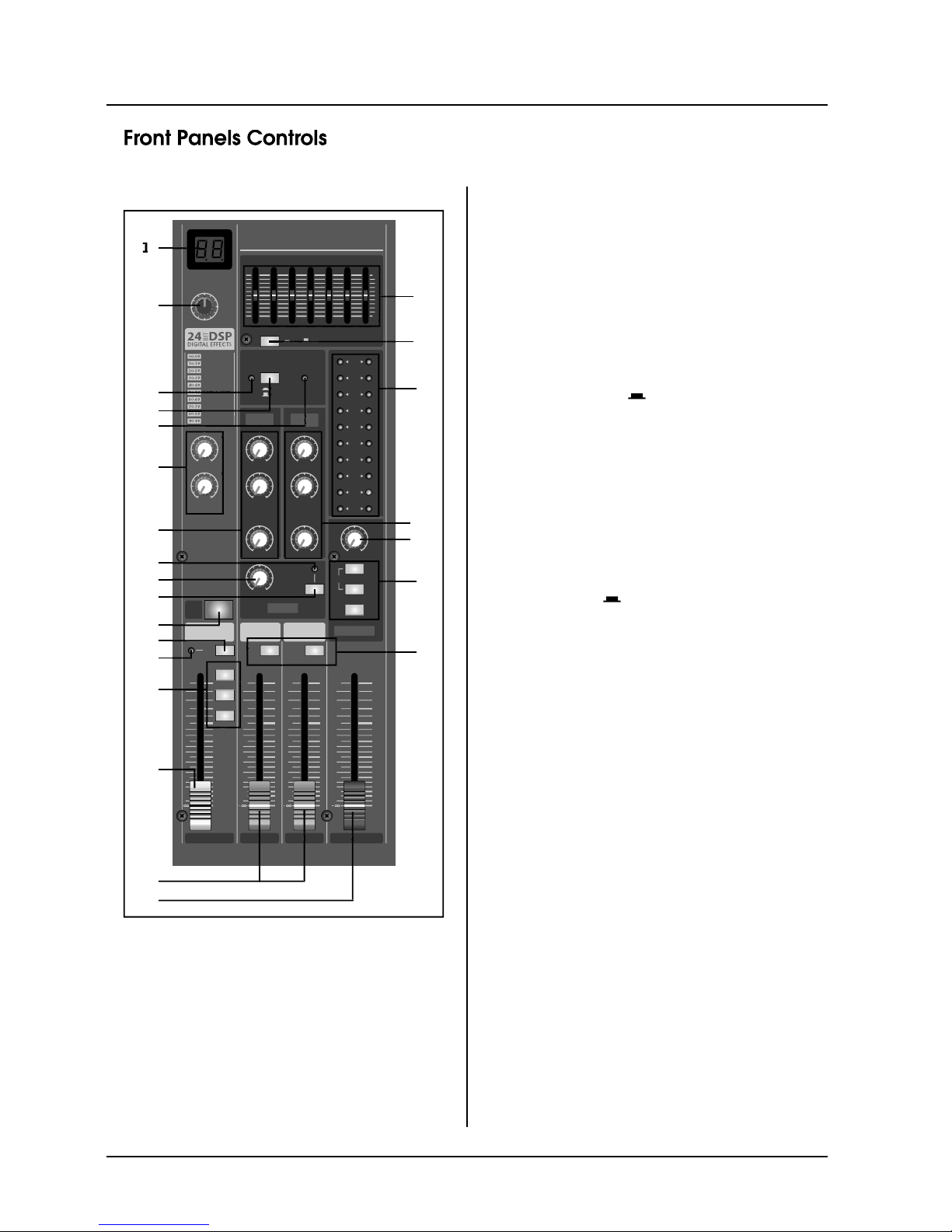
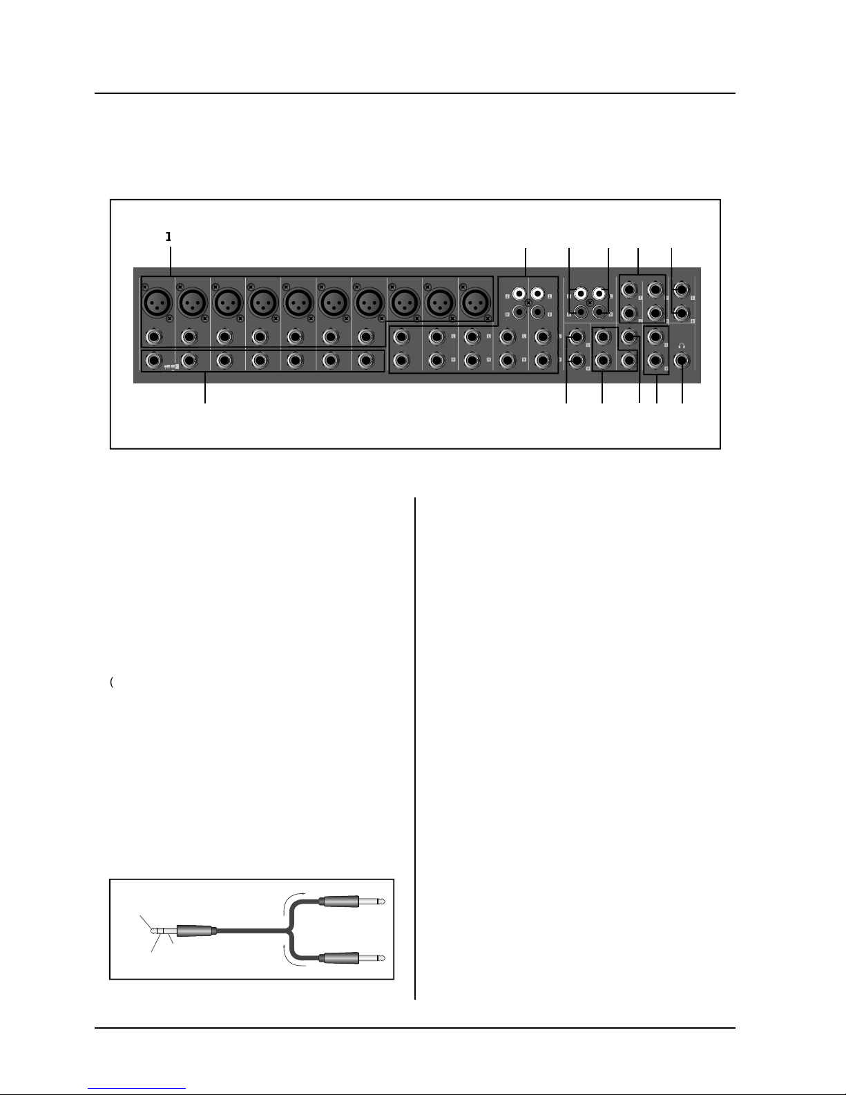
23. PHANTOM POWER SWITCH
This switch to
ou set
the switch on, the mixer su
ower to all channels
that provide XLR MIC input
et this switch on when usin
one or more condenser
micro
18. CTRL ROOM /PHONES CONTROL
ontrols the level of the si
. LEVEL METER
This LED displa
shows the level of the si
the selection switches described in the 17 above
LEVEL METER SIGNAL SWITCHES
orresponds to the standard output level of +4dB for
hts up red when the output hits the clippin
0. MAIN EQ ON/OFF Switch
The E
FF switch is used to engage or bypass
the MAIN E
UALIZER. When the switch is in the
down position, the E
is on and when the switch is up,
the E
1. MAIN STEREO EQUALIZER
The M1636FX
M2436FX provide a seven-band MAIN
ou to control the
frequenc
response of the MAIN stereo mix bus si
the frequencies that cause anno
at when the sliders are in
the center position. Movin
a slider in the positive direc-
tion will boost that frequenc
up to 12dB. And since the MAIN GRAPH-
IC E
curve is applied to
both the le
2. PHANTOM POWER INDICATOR
This indicator li
hts when the phantom power switch is
t
n.
Be sure to leave this switch o
s are connected to the XLR input
acks.
Devices other than condenser MI
ed if connected to the phantom power suppl
.
Note, however, that the switch ma
namic microphones.
To avoid dama
e to speakers, be sure to turn o
this switch on or off. We also recommend that
the switch, to avoid risk of loud noises that could
ou wish to output the TAPE IN
. TAPE IN CONTROL
This knob control the level o
nal that
is inserted to the master mixin
. LEVEL-METER SIGNAL SWITCHES
These level-meter switches, to
ether with the channel
PFL switches, select the si
4. POWER INDICATOR
This indicator li
hts when the mixer power switch is
t
hen this switch is on, the mixer supplies DC
48V power to pins 2 and 3 o