5
M822FX-USB / M1022-USB
M822FX / M1022
Front Panel Controls
Front Panel Controls
ON
OFF
ON
OFF
PHANTOM POWER
PROGRAM
POWER
TAPE/USB
AUX RETURN
LEVEL
LEVEL
0
5
10
LEVEL LEVEL
0
5
10
LEVEL
EFFECTS CTRL-R/PHONES
0
5
10
MAIN L/R
RL
SELECT
-20
-10
-7
-4
-2
0
+2
+4
+7
CLIP
0 10
5
0 10
5
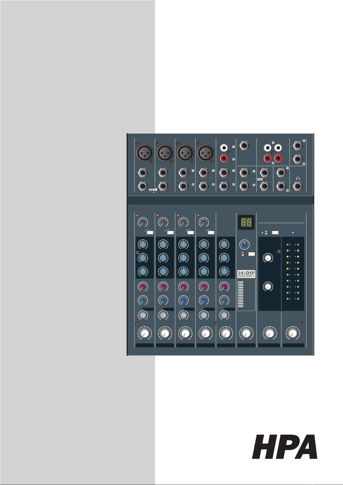
8 CH MIXING CONSOLE
M822FX-USB HPA
PERFORMANCE
HALL REVERB
PLATE REVERB
SPRING REVERB
ECHO
FLANGE+VERB
CHORUS+VERB
ECHO+VERB
CHORUS
FLANGE
1
1.MAIN CONTROL SECTION
(1). DSP PROGRAM DISPLAY
The Program Number LED displays the number of the se-
lected effects program.
(2). DSP PROGRAM SELECT SWITCH
Theprogram knobselects oneof the100built-indigital effects,
for each number you select. 24 Bit Digital Effects processor
with high quality, studio grade effects like Delay, Chorus and
Reverb.
(3). DSP ON/ OFF SWITCH
This switch turns the internal digital effect on/off.
(4). EFX RTN VOLUME
Adjust the level of the signal sent from the internal digital ef-
fect to the main bus.
(5). CTRL ROOM /PHONES CONTROL
Controls the level of the signal output to the PHONES jack
and the CTRL ROOM L and R jacks.
(6). MAIN L/R MASTER VOLUME
from all channels.
*No. 1~4areappliedonly toM822FX / M822FX-USB
(7). STEREO RETURN CONTROL
Adjust thelevelof themixed L/R signal sent from the RETURN
jack (L (MONO) and R) to the Main L/R bus.
(8). TAPE IN CONTROL
This control adjusts the level of the playback signal that is
inserted to the master mixing bus from the TAPE IN RCA jacks
on the top panel.
(9). OUTPUT LEVEL METER
A vertical row of ten LED show the continuous output level of
main Output L/R.
This type of display is free from over shoot problem of me-
chanical meters and is highly visible under poor lighting condi-
tions. The 0 LED means an output level of +4dB for +4dB
output (that’s the rated level).
(10). POWER INDICATOR
This indicator lights when the power switch is turned on.
(11). PHANTOM POWER SWITCH
This switch toggles phantom power on or off.If you set the switch
on, the mixer supplies power to all channels that provide XLR
mic input jacks. Set this switch on when using one or more
condenser microphones.
2
3
4
5
67
8
9
10
11
12
When this switch is on, the mixer supplies DC +48V
power to pins 2 and 3 of all XLR-type MIC INPUT
jacks.
Be sure to leave this switch off ( ) if you do not need
phantom power.
When pressed the switch on ( ), be sure that only con-
denser mics are connected to the XLR input jacks.
Note, however, that the switch may be left on without
problem when connecting to balanced dynamic
microphones.
To avoid damage to speakers, be sure to turn off
switch on or off. We also recommend that you turn all
out controls ( MAIN L/R , CTRL - R / phones , etc).
to minimum settings before operating the switch, to
avoid risk of loud noises that could cause hearing loss
or device damage.
(12). PHANTOM POWER INDICATOR
This indicator lights when the phantom power switch is turned
on.
NOTE:
*
*
*