3
Connecting the Battery Cables to the Solar Inverter
2.3
•Do not connect or disconnect battery cables when the solar inverter is running. Failing to do so may cause electric shocks.
•Before connecting battery cables, ensure that the DC switch and all the switches connecting to the solar inverter are OFF, and the
solar inverter has no residual electricity. Otherwise the high voltage of the solar inverter and battery may result in electric shocks.
•If no battery is configured, do not remove the watertight cap from the battery terminal. Otherwise the solar inverter will not comply
with its Ingress Protection Rating. If a battery is configured, set aside the watertight cap. Reinstall the watertight cap immediately
after removing the connector. The high voltage of the battery terminal may result in electric shocks.
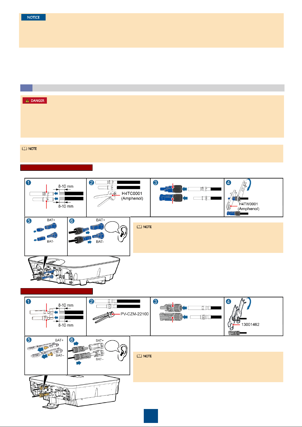
Blue positive connector
Blue negative connector
Positive metal terminal
Negative metal terminal Ensure that the cable will not
be extracted after crimped.
Ensure that
the locking
nut is secured.
Pull the power cable back to ensure that it
is connected securely.
Click
Pull the battery cable back to
ensure that it is connected securely.
Press the buckle springs
and then remove the
watertight caps.
1. Assemble the positive and negative connectors, and then connect the power cable.
•If the battery fails to connect to the solar inverter, contact Huawei customer service hotline and set the Auxiliary Power ON/OFF
switch to OFF. Otherwise the battery power will be exhausted and the battery cannot be charged.
•If the solar inverter is not powered on or the battery is not connected to the solar inverter, switch Auxiliary Power to OFF position.
Otherwise the battery power will be exhausted and the battery cannot be charged.
•Ensure that the AC and DC disconnections are turned off before connecting the power cable to the battery pack.
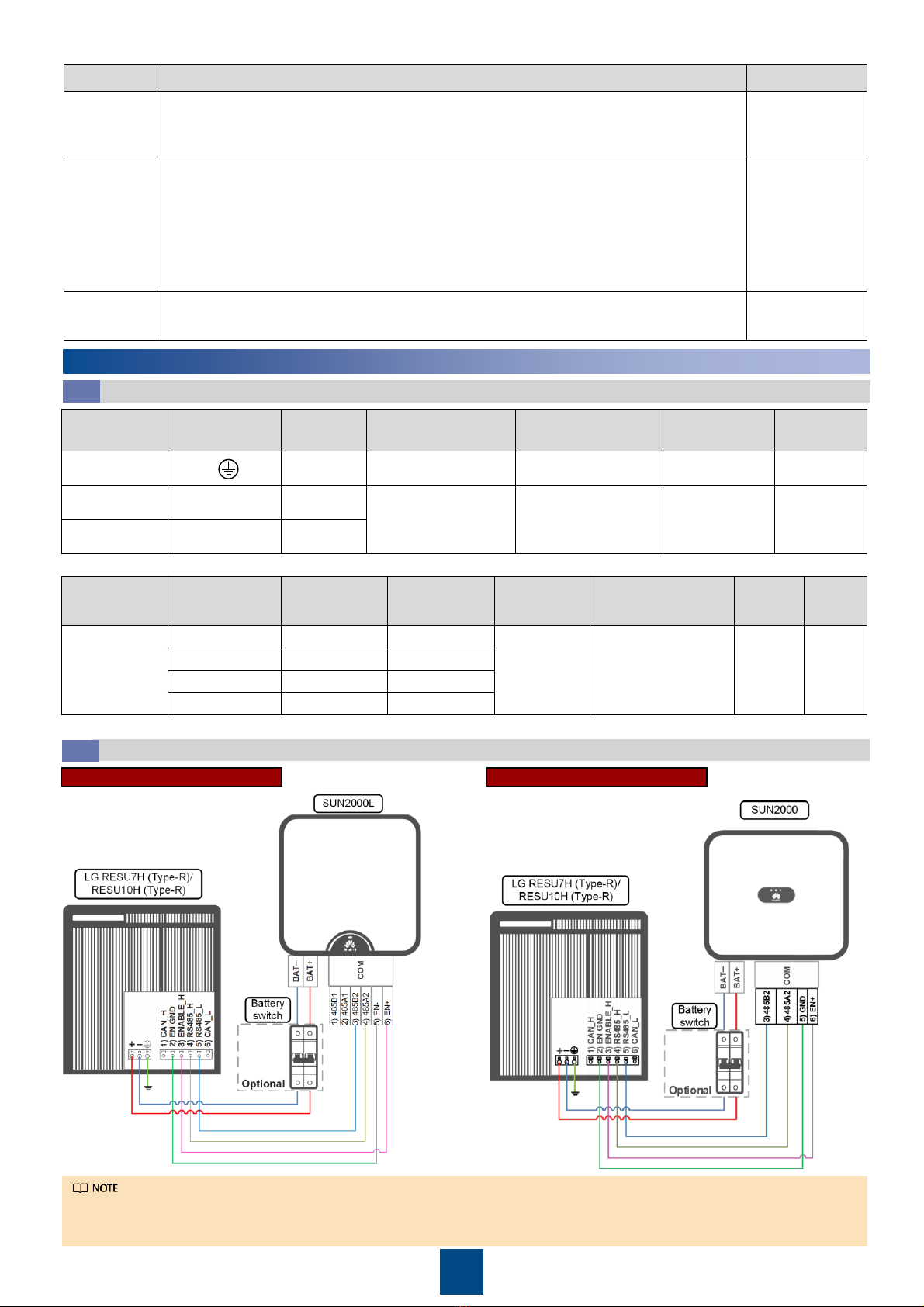
1. Connect the power cable.
a) Connect the ground cable.
b) Connect the negative line of the power cable.
c) Connect the positive line of the power cable.
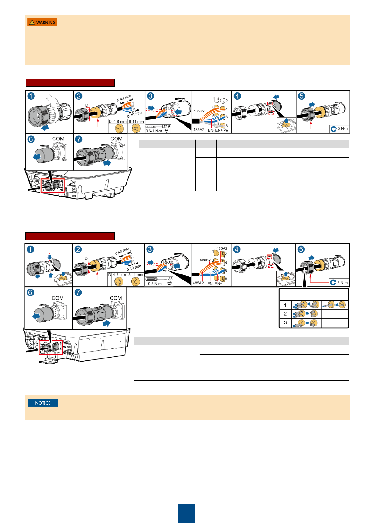
2. Connect the communications cable.
At first, connect the wire to terminal 2) EN GND. Then, make connections to the 3) ENABLE_H, 4) RS485_H, and 5) RS485_L terminals
one after another.
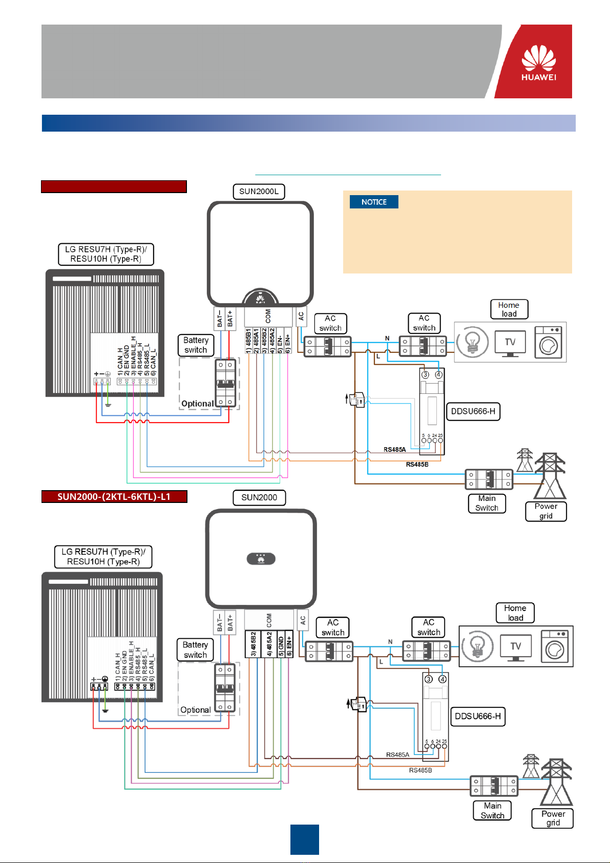
SUN2000L-(2KTL-5KTL)
SUN2000-(2KTL-6KTL)-L1
Positive connector
Negative connector
Positive metal terminal
Negative metal terminal Ensure that the cable will not
be extracted after crimped.
Ensure that
the locking
nut is secured.
Pull the power cable back to ensure that it
is connected securely.
Click
Pull the battery cable back to
ensure that it is connected securely.
Remove the watertight
caps. Use the Staubli MC4 positive and negative terminals and DC connectors
supplied with the solar inverter. Using incompatible positive and negative
terminals and DC connectors may result in serious consequences. The caused
device damage is not covered under warranty.
Use the Amphenol positive and negative terminals and DC connectors
supplied with the solar inverter. Using incompatible positive and negative
terminals and DC connectors may result in serious consequences. The
caused device damage is not covered under warranty.
The types of battery terminals used by SUN2000L-(2KTL-5KTL) and SUN2000-(2KTL-6KTL)-L1 are different.