Huber MPC RotaCool User manual

MPC RotaCool®


OPERATION MANUAL
MPC RotaCool®


OPERATION MANUAL
V2.3.0en/04.08.21//1.30 RotaCool®
5
RotaCool®
MPC®
This operation manual is a translation of the original operation manual.

OPERATION MANUAL
RotaCool® V2.3.0en/04.08.21//1.30
6
The variants of the
MPC controller. Mini
Chiller/Unichiller,
Unichiller, MPC Im-
mersion circulator (top
to bottom)

OPERATION MANUAL
V2.3.0en/04.08.21//1.30 RotaCool®
7
Table of contents
V2.3.0en/04.08.21//1.30
1Introduction 12
1.1 Identification / symbols in the operation manual ......................................... 12
1.2 Information on the EU Declaration of Conformity......................................... 12
1.3 Safety .......................................................................................................... 12
1.3.1 Symbols used for Safety Instructions..............................................................12
1.3.2 Representation of safety identifiers on the temperature control unit...........13
1.3.3 Proper operation.............................................................................................14
1.3.4 Reasonably foreseeable misuse......................................................................14
1.4 Responsible bodies and operators – Obligations and requirements............... 15
1.4.1 Obligations of the responsible body ...............................................................15
1.4.1.1 Proper disposal of resources and consumables .........................................15
1.4.1.2 Temperature control unit with natural refrigerants (NR) ..........................16
1.4.1.3 Temperature control units with fluorinated greenhouse gases/refrigerants17
1.4.2 Requirements for operators ...........................................................................17
1.4.3 Obligations of the operators...........................................................................17
1.5 General information..................................................................................... 18
1.5.1 Description of workstation .............................................................................18
1.5.2 Safety devices to DIN 12876 ...........................................................................18
1.5.3 Further protective devices ..............................................................................19
1.5.3.1 Power interruption.....................................................................................19
1.6 Exemplary illustrations of the cooling variants.............................................. 19
1.6.1 Consequence of inadequate energy dissipation.............................................20
2Commissioning 21
2.1 In-plant transport......................................................................................... 21
2.1.1 Lifting and transporting the temperature control unit...................................21
2.1.1.1 Temperature control unit with lifting eyes ................................................21
2.1.1.2 Temperature control unit without lifting eyes...........................................22
2.1.2 Mounting/removing leveling feet...................................................................22
2.1.3 Positioning the temperature control unit.......................................................23
2.1.3.1 Temperature control unit with casters ......................................................23
2.1.3.2 Temperature control unit without casters.................................................23
2.2 Unpacking.................................................................................................... 23
2.3 Ambient conditions...................................................................................... 23
2.3.1 EMC-specific notes..........................................................................................25
2.4 Installation conditions.................................................................................. 25
2.5 Recommended temperature control hoses................................................... 25
2.6 Wrench sizes and torques............................................................................. 26
2.7 Preparations for operation ........................................................................... 26
2.7.1 Unscrewing/activating the leveling feet (if any) .............................................26
2.7.2 Opening/closing valves ...................................................................................27
2.7.3 Installing collecting container .........................................................................27
2.7.4 Install additional work surface (optional) .......................................................27
2.7.5 Connecting the functional earth.....................................................................27
2.8 Connecting externally closed application...................................................... 28
2.8.1 Connecting an externally closed application ..................................................28
2.9 Connecting to the power supply ................................................................... 28

OPERATION MANUAL
RotaCool® V2.3.0en/04.08.21//1.30
8
2.9.1 Connection using socket with protective earth (PE).......................................28
2.9.2 Connection via hard wiring .............................................................................29
3Function description 30
3.1 Function description of the temperature control unit ................................... 30
3.1.1 General functions............................................................................................30
3.1.2 Other functions...............................................................................................30
3.2 Information on the thermal fluids ................................................................ 30
3.3 To be noted when planning the test ............................................................. 31
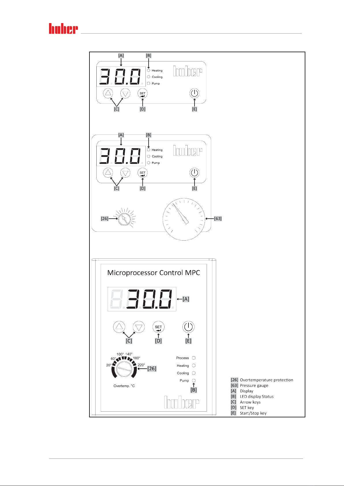
3.4 Display and control instruments................................................................... 32
3.4.1 Display.............................................................................................................32
3.4.2 LED display status ...........................................................................................32
3.4.3 Arrow keys ......................................................................................................32
3.4.4 SET key ............................................................................................................32
3.4.5 Start/Stop key .................................................................................................32
3.5 Menu function ............................................................................................. 33
3.6 Function examples ....................................................................................... 33
3.6.1 Display setpoint ..............................................................................................33
3.6.2 Set/change setpoint........................................................................................33
3.6.3 Changing the Auto-Start function ...................................................................33
4Setup mode 35
4.1 Setup mode ................................................................................................. 35
4.1.1 Turning on the temperature control unit .......................................................35
4.1.2 Turning off the temperature control unit.......................................................35
4.1.3 Setting the setpoint ........................................................................................35
4.2 Filling, venting and draining ......................................................................... 35
4.2.1 Filling and venting externally closed application ............................................36
4.2.2 Draining externally closed applications ..........................................................37
5Normal operation 38
5.1 Automatic operation .................................................................................... 38
5.1.1 Temperature control.......................................................................................38
5.1.1.1 Starting the temperature control process..................................................38
5.1.1.2 Ending the temperature control process ...................................................38
6Service/maintenance 39
6.1 Displays in the event of faults....................................................................... 39
6.2 Maintenance................................................................................................ 39
6.2.1 Function check and visual inspection .............................................................40
6.2.2 Replacing temperature control hoses.............................................................41
6.2.3 Clean liquefier fins (air-cooled temperature control unit) .............................41
6.3 Thermal fluid inspection, replacement and circuit cleaning........................... 42
6.3.1 Thermal fluid replacement .............................................................................42
6.3.1.1 Externally closed application......................................................................42
6.3.2 Rinsing the thermal fluid circuit......................................................................42
6.4 Cleaning the surfaces ................................................................................... 44
6.5 Inspect the mechanical seal.......................................................................... 44
6.6Plug contacts................................................................................................ 44
6.7 Decontamination/repairs ............................................................................. 44
7Shutting down 46
7.1 Safety instructions and basic principles ........................................................ 46

OPERATION MANUAL
V2.3.0en/04.08.21//1.30 RotaCool®
9
7.2 Switch-off .................................................................................................... 46
7.3 Draining the temperature control unit.......................................................... 47
7.4 Deinstalling the collecting container............................................................. 47
7.5 Uninstalling an external application ............................................................. 47
7.6 Packing ........................................................................................................ 47
7.7 Shipping....................................................................................................... 47
7.8 Disposal ....................................................................................................... 48
7.9 Contact data ................................................................................................ 48
7.9.1 Telephone number: Customer Support ..........................................................48
7.9.2 Telephone number: Sales ...............................................................................48
7.9.3Email address: Customer Support...................................................................48
7.10 Certificate of Compliance ............................................................................. 49
8Annex 50

OPERATION MANUAL
RotaCool® V2.3.0en/04.08.21//1.30
10

OPERATION MANUAL
V2.3.0en/04.08.21//1.30 RotaCool®
11
Foreword
Dear Customer,
Thank you for choosing a temperature control unit from Peter Huber Kältemaschinenbau AG. You
have made a good choice. Thank you for your trust.
Please read the operation manual carefully before putting the unit into operation. Strictly follow all
notes and safety instructions.
Follow the operation manual with regard to transport, start-up, operation, maintenance, repair,
storage and disposal of the temperature control unit.
We fully warrant the temperature control unit for the specified intended operation.
The models listed on page 5 are referred to in this operation manual as temperature control units
and Peter Huber Kältemaschinenbau AG as Huber company or Huber.
Liability for errors and misprints excluded.
The following trademarks and the Huber logo are registered trademarks of Peter Huber Kältemaschinenbau AG
in Germany and/or other countries worldwide: BFT®, CC®, Chili®, Com.G@te®, Compatible Control®, CoolNet®,
DC®, E-grade®, Grande Fleur®, Huber Piccolo®, KISS®, Minichiller®, Ministat®, MP®, MPC®, Peter Huber Mini-
chiller®, Petite Fleur®, Pilot ONE®, RotaCool®, Rotostat®, SpyControl®, SpyLight®, Tango®, TC®, UC®, Unical®,
Unichiller®, Unimotive®, Unipump®, Unistat®, Unistat Tango®, Variostat®. The following trademarks are regis-
tered in Germany to DWS Synthesetechnik: DW-Therm®, DW-Therm HT®. The following trademark is a registered
trademark of BASF SE: Glysantin®.

Introduction
OPERATION MANUAL Chapter 1
RotaCool® V2.3.0en/04.08.21//1.30
12
1Introduction
1.1 Identification / symbols in the operation manual
The following identifications and symbols are used in the texts and illustrations.
Identification / symbol Description
→Reference to information / procedure.
»TEXT« Reference to a chapter in the operation manual. In the digital version, the text
is clickable.
>TEXT< [NUMBER] Reference to the wiring diagram in the annex. The designation and the search
digit are specified.
>TEXT< [LETTER] Reference to a drawing in the same paragraph. The designation and the
search digit are specified.
▪List, first level
‒List, second level
1.2 Information on the EU Declaration of Conformity
The equipment complies with the basic health and safety requirements of the European Directives
listed below:
▪Machinery Directive
▪Low Voltage Directive
▪EMC Directive
1.3 Safety
1.3.1 Symbols used for Safety Instructions
Safety instructions are marked by the below combinations of pictograms and signal words. The
signal word describes the classification of the residual risk when disregarding the operation manual.
Denotes an immediate hazardous situation that will result in death or serious injuries.
Denotes a general hazardous situation that may result in death or serious injuries.
Denotes a hazardous situation that can result in injury.
Denotes a situation that can result in property material damage.
Denotes important notes and usable hints.
Overview

Introduction
Chapter 1 OPERATION MANUAL
V2.3.0en/04.08.21//1.30 RotaCool®
13
The safety information in this operation manual is designed to protect the operating company, the
operator and the equipment from damage. First inform yourself about any residual risks due to
misuse before you start an operation.
1.3.2 Representation of safety identifiers on the temperature control unit
The following pictograms are used as safety identifiers. The table gives an overview of the safety
identifiers used here.
Identifier Description
Mandatory sign
- Observe the instructions
Warning sign
- General warning sign
- Observe the instructions
- Warning of electrical voltage
- Warning of hot surface
- Warning of flammable substances
Safety information and
procedure
Overview

Introduction
OPERATION MANUAL Chapter 1
RotaCool® V2.3.0en/04.08.21//1.30
14
1.3.3 Proper operation
Operating the temperature control unit in a potentially explosive area
DEATH THROUGH EXPLOSION
Do NOT install or start up the temperature control unit within an ATEX zone.
Improper use
SERIOUS INJURY AND PROPERTY DAMAGE
Store the operation manual where it is easy to access in close proximity to the temperature
control unit.
Only adequately qualified operators may work with the temperature control unit.
Operators must be trained before handling the temperature control unit.
Check that the operators have read and understood the operation manual.
Define precise responsibilities of the operators.
Personal protective equipment must be provided to the operators.
Be sure to follow the responsible body’s safety rules to protect life and limb and to limit dam-
ages!
Modifications to the temperature control unit by third-parties
DAMAGE TO THE TEMPERATURE CONTROL UNIT
Do not allow third parties to make technical modifications to the temperature control unit.
The EU declaration of conformity becomes invalid if any modifications are made to the tem-
perature control unit without the approval of Huber.
Only specialists trained by Huber may carry out modifications, repairs or maintenance work.
The following must be observed without fail:
Only use the temperature control unit in a fault-free condition!
Have the start-up and repairs carried out by specialists only!
Do not ignore, bypass, dismantle or disconnect any safety devices!
The temperature control unit must not be used for any purposes other than temperature control in
accordance with the operation manual.
The temperature control unit is made for industrial use. The temperature control unit is used to
maintain the temperature of applications, such as glass or metal reactors or other expedient items
in laboratories and industry. Flow-through coolers and calibration baths must be used only in com-
bination with Huber temperature control units. Only use thermal fluids suitable for the overall sys-
tem. The cooling or heating capacity is provided at the pump connections or - where present - in the
tempering bath. For the technical specification, refer to the datasheet. →From page 50, section
»Annex«. Install, set up and operate the temperature control unit according to the instructions in
this operation manual. Any failure to comply with the operation manual is considered as improper
operation. The temperature control unit was manufactured according to the state of the art and the
recognized safety rules and regulations. Safety devices are installed in your temperature control
unit.
1.3.4 Reasonably foreseeable misuse
Use with medical devices (e.g. in Vitro diagnostic procedure) or for direct foodstuff temperature
control is NOT permissible.
The temperature control unit must NOT be used for any purposes other than temperature control in
accordance with the operation manual.
The manufacturer accepts NO liability for damage caused by technical modifications to the temper-
ature control unit, improper handling or use of the temperature control unit if the operation manu-
al is not observed.

Introduction
Chapter 1 OPERATION MANUAL
V2.3.0en/04.08.21//1.30 RotaCool®
15
1.4 Responsible bodies and operators – Obligations and
requirements
1.4.1 Obligations of the responsible body
The operation manual is to be stored where it is easy to access in close proximity to the temperature
control unit. Only adequately qualified operators (e.g. chemists, CTA, physicists etc.) are permitted
to work with the temperature control unit. Operators must be trained before handling the tempera-
ture control unit. Check that the operators have read and understood the operation manual. Define
precise responsibilities of the operators. Personal protective equipment must be provided to the
operators.
▪The responsible body must install a condensation water / thermal fluid drip tray below the tem-
perature control unit.
▪The use of a drip tray may be prescribed by national legislation for the installation area of the
temperature control unit (incl. accessory). The responsible body must check and apply the na-
tional regulations applicable for it accordingly.
▪The temperature control unit complies with all applicable safety standards.
▪Your system, which uses our temperature control unit, must be equally safe.
▪The responsible body must design the system to ensure it is safe.
▪Huber is not responsible for the safety of your system. The responsible body is responsible for the
safety of the system.
▪Although the temperature control unit provided by Huber meets all the applicable safety stand-
ards, integration into a system may give rise to hazards that are characteristic of the other sys-
tem’s design and beyond the control of Huber.
▪It is the responsibility of the system integrator to ensure that the overall system, into which this
temperature control unit is integrated, is safe.
▪The >Mains isolator< [36] (if present) can be locked in the off position to facilitate safe system
installation and maintenance of the temperature control unit. It is the responsibility of the re-
sponsible body to develop any lock-out/tag-out procedure for the energy source in accordance
with local regulations (e.g. CFR 1910.147 for the US).
1.4.1.1 Proper disposal of resources and consumables
Do comply with all national disposal regulations applicable for you. Contact your local waste man-
agement company for any questions concerning disposal.
Material / Aids Disposal / Cleaning
Packaging material Keep the packaging material for future use (e.g. transport).
Thermal fluid
Please refer to the safety data sheet of the thermal fluid used for information on its
proper disposal.
Use the original thermal fluid container when disposing it.
Filling accessories, e.g.
beaker
Clean the filling accessories for reuse. Make sure that the materials and cleaning
agents used are properly disposed of.
Aids such as towels,
cleaning cloths
Tools used to take up spilled thermal fluid must be disposed of in the same fashion
as the thermal fluid itself.
Tools used for cleaning must be disposed of depending on the cleaning agent used.
Cleaning agents such as
stainless steel cleaning
agents, sensitive-fabrics
detergents
Please refer to the safety data sheet of the cleaning agent used for information on its
proper disposal.
Use the original containers when disposing of large quantities of cleaning agents.
Consumables such as air
filter mats, temperature
control hoses
Please refer to the safety data sheet of the consumables used for information on
their proper disposal.
Overview

Introduction
OPERATION MANUAL Chapter 1
RotaCool® V2.3.0en/04.08.21//1.30
16
1.4.1.2 Temperature control unit with natural refrigerants (NR)
Over 8 g refrigerant per m³ room air
DEATH OR SERIOUS INJURY DUE TO EXPLOSION
Observe the rating plate (amount of natural refrigerant contained) and the room size (maxi-
mum room concentration of natural refrigerant in case of leakage) when installing the temper-
ature control unit.
Over 8 g refrigerant per m³ room air: A gas warning sensor must be fitted and functioning.
The gas warning sensor must be calibrated and maintained at regular intervals (between 6 and
12 months).
The temperature control unit is not approved for operation in an ATEX zone.
Huber products with natural refrigerants work with numerous proven, safe and highly-sustainable
technologies. The relevant standards and regulations for temperature control units with natural
refrigerants contain a number of stipulations, the importance of complying with which is set out
below. Please additionally: →Page 14, section »Proper operation«.
Huber temperature control units are constructed to be permanently sealed and are carefully
checked for leak tightness. Temperature control units with more than 150 g natural refrigerant are
equipped with an additional gas warning sensor.
For the filling capacity of the temperature control unit, refer to the data sheet. →From page 50,
section »Annex«. Or to the rating plate on the back of the temperature control unit. Please also
consider: →Page 23, section »Ambient conditions« and →Page 25, section »Installation condi-
tions«.
Class of
application
field
Application field Example of the installation
location
Max.
quantity of
refrigerant
AND
Max. permissible
quantity above
ground level (GL)
A General Publicly accessible area in a
public building
8 g/m3
ambient air
1.5 kg
B Monitored Laboratories 2.5 kg
C
Access only for
authorized
persons
Production equipment 10.0 kg
Temperature control units with more than 1 kg refrigerant must not be installed below ground level (GL).
Temperature control units with up to 150 g natural refrigerant
▪The temperature control unit has been constructed to the requirements of EU and EFTA coun-
tries.
▪Use the table as guidance for classifying the application field. Respect the max. refrigerant quanti-
ty stated therein.
Temperature control units with more than 150 g natural refrigerant
▪The temperature control unit has been constructed to the requirements of EU and EFTA coun-
tries.
▪Use the table as guidance for classifying the application field. Respect the max. refrigerant quanti-
ty or the permissible highest quantity above ground level (GL) stated therein.
▪For more information about the pre-installed gas detection sensor:
-The built-in gas detection sensor enables a safety shutdown at 20% of the lower explosive
limit via a power disconnect relay that is to be installed by the responsible body. The
temperature control unit is thus switched off early and safely in case of fault.
-A 24 V DC external power supply must be available for the pre-installed gas warning sen-
sor. The alarm output of the gas warning sensor uses a 4 - 20 mA signal. Please refer to the
data sheet of the gas warning sensor for further technical information. A separate pro-
cessing unit is available as an accessory for the control of the power disconnect relay. The
processing unit provides a potential-free switching contact and simultaneously provides
the power supply and analysis of the gas warning sensor. Both variants require the respon-
Classifying the applica-
tion field

Introduction
Chapter 1 OPERATION MANUAL
V2.3.0en/04.08.21//1.30 RotaCool®
17
sible body to provide the necessary dimensioning and installation. Please refer to the data
sheet of the gas warning sensor for the technical information necessary for the installa-
tion. The alarm of the gas detection system can be connected to the responsible body’s
alarm control unit. The responsible body is responsible for this and for the other measures.
-The responsible body is responsible for the calibration of the gas detection sensor prior to
initial operation and the observance of calibration and maintenance intervals according to
the operation manual. We recommend to set calibration and maintenance intervals be-
tween 6 and 12 months if no information is provided. For increased safety requirements,
shorter intervals can be specified. On request we will recommend a specialist company to
carry out the calibration and maintenance.
1.4.1.3 Temperature control units with fluorinated greenhouse gases/refrigerants
F gases regulation (EC) No. 517/2014 of April 16, 2014, on fluorinated greenhouse gases, and re-
pealing Regulation (EC) No. 842/2006.
These regulations deal with all systems that contain fluorinated refrigerants. The substances dealt
with in Directive (EC) No. 1005/2009 of the European Parliament and of the Council of 16 September
2009 that deplete the ozone layer are excluded (CFC/HCFC).
The directive regulates the reduction of the emission, utilization, recovery, and destruction of cer-
tain fluorinated greenhouse gases. It also regulates the identification and disposal of products and
devices that contain these gases. Since July 4, 2007, responsible bodies must check their stationary
refrigeration systems for leaks at regular intervals, and have any leaks eliminated immediately.
Directive (EC) No. 303/2008 contains stipulations on the training and certification of companies and
personnel that are permitted to execute the specified activities.
Obligations of the responsible bodies:
▪Directive (EC) No. 842/2006 already imposed a number of obligations upon responsible bodies
regarding certain fluorinated greenhouse gases. The new Ordinance on Fluorinated Greenhouse
Gases upholds these to a large extent. Some duties are added while others are designed different-
ly by this new ordinance. Please refer to the text of this ordinance for a complete overview of the
individual responsibilities of responsible bodies.
▪General obligation to reduce emissions.
▪Only certified companies may maintain, repair or decommission refrigeration systems. The re-
sponsible bodies must verify that these companies are certified.
▪Regular leak tests of stationary refrigeration systems by certified personnel (such as Huber service
engineers). The required test interval is based on the refrigerant filling capacity and the type of
refrigerant, converted to CO22 equivalent.
▪Responsibility of responsible bodies operating a plant to recover F-gases by certified personnel.
▪Obligatory documentation requirement in the refrigeration system’s operation manual, specifying
type and volume of refrigerant used or recovered. The responsible body must keep the records
for at least 5 years after their creation and present it to the responsible authority upon request.
▪Temperature control units with natural refrigerants (NR) are exempt from this Directive.
▪Please refer to the data sheet or rating plate of your temperature control unit for the quantity
and type of refrigerant.
▪Additional information about the definition of the inspection interval can be found on our web-
site.
1.4.2 Requirements for operators
Work on the temperature control unit is reserved for appropriately qualified specialists, who have
been assigned and trained by the responsible body to do so. Operators must be at least 18 years old.
Under 18-year olds may operate the temperature control unit only under the supervision of a quali-
fied specialist. The operator is responsible vis-a-vis third-parties in the work area.
1.4.3 Obligations of the operators
Carefully read the operation manual before operating the temperature control unit. Please observe
the safety instructions. When operating the temperature control unit, wear appropriate personal
protective equipment (e.g. safety goggles, protective gloves, non-slip shoes).

Introduction
OPERATION MANUAL Chapter 1
RotaCool® V2.3.0en/04.08.21//1.30
18
1.5 General information
1.5.1 Description of workstation
The workstation is located at the control panel in front of the temperature control unit. The work-
station is determined by the customer's connected peripheries. Accordingly, it must be designed
safe by the responsible body. The workstation design also depends on the applicable requirements
of the German occupational health and safety regulations [BetrSichV] and the risk analysis for the
workstation.
1.5.2 Safety devices to DIN 12876
The rating of your temperature control unit is stated on the data sheet in the appendix.
Classification Temperature
control medium Technical requirements Identification d)
I Non-combustible a) Overheat protection c) NFL
II Combustible b) Adjustable overheat protection FL
III Combustible b) Adjustable overtemperature protection
and additional low-level protection FL
a) Usually water; other fluids only if non-combustible even within the temperature range of an individual fault.
b) The temperature control media must have a fire point of ≥ 65 °C.
c) The overheat protection can, for instance, be realized using a suitable fill level sensor or a suitable temperature
limiter.
d) Optional at the choice of the manufacturer.
▪Temperature control units with heating correspond to class number III/FL. These temperature
control units are characterized by an “H” in the device name.
▪Temperature control units without heating correspond to class number I/NFL.
Rating of laboratory
thermostats and
laboratory baths
Overview of the tem-
perature thresholds

Introduction
Chapter 1 OPERATION MANUAL
V2.3.0en/04.08.21//1.30 RotaCool®
19
1.5.3 Further protective devices
Emergency strategy – interrupt the power grid connection!
To determine the type of switch or switch combination your temperature control unit is equipped
with, please refer to the wiring diagram. →From page 50, section »Annex«.
Temperature control units with >Mains isolator< [36] (red/yellow or gray): Turn the >Mains
isolator< [36] to the “0” position.
Temperature control units with >Mains isolator< [36] (red/yellow) and additional >Appliance
switch< [37] (gray): Turn the >Mains isolator< [36] to the “0” position. Then turn the >Appliance
switch< [37] to the “0” position!
Temperature control units with >Mains isolator< [36] (gray) and >Emergency stop switch< [70]
(red/yellow): Press the >Emergency stop switch< [70]. Then turn the >Main switch< [36] to the
“0” position!
Temperature control units with >Mains switch< [37]:Power supply via socket: Disconnect the
temperature control unit from the power supply. Then turn the >Mains isolator< [37] to the “0”
position! Power supply via hard wiring: Disconnect the power grid supply by means of the build-
ing’s circuit breaker. Then turn the >Mains isolator< [37] to the “0” position!
Temperature control units without a switch or inside a protective housing: Connection via sock-
et: Disconnect the temperature control unit from the power supply. Connection via hard wiring:
Disconnect the power grid supply by means of the building’s circuit breaker!
1.5.3.1 Power interruption
Following a power outage (or when switching on the temperature control unit), this function can be
used to determine how the temperature control unit is supposed to respond.
Auto start function switched off
The temperature control is started only by manual input when the temperature control unit is
turned on.
Auto start function switched on
The temperature control unit is set to the same state it was in before the power outage. For exam-
ple, before the power outage: Temperature control is off; after power outage: Temperature control
is off. If temperature control was active during a power outage, the process will automatically con-
tinue after the power outage.
→Page 33, section »Changing the Auto-Start function«.
1.6 Exemplary illustrations of the cooling variants
Example: Air and
water cooling

Introduction
OPERATION MANUAL Chapter 1
RotaCool® V2.3.0en/04.08.21//1.30
20
1.6.1 Consequence of inadequate energy dissipation
Room air/cooling water
Consequences of, for instance, contamination of the liquefier fins, inadequate clearance between
temperature control unit to wall/bath wall, room air/cooling water too warm, cooling water differ-
ential pressure too low, suction strainer contamination: The refrigerant in the coolant circuit can no
longer fully discharge the admitted energy to the room air/cooling water. Thus there is not sufficient
liquefied refrigerant available, the condensation temperature and the energy consumption to rise.
Coolant circuit
Consequences of inadequate refrigerant quantity/rising condensation temperature: Not all the
cooling capacity from the coolant circuit is available at the evaporator. This means reduced energy
transmission from the thermal fluid circuit.
Thermal fluid circuit
Consequence of inadequate energy dissipation from the thermal fluid: The thermal fluid can only
dissipate the energy from your application to a limited extent.
Application
Consequences of inadequate energy dissipation from the application: The energy created (exother-
mic) in the application can no longer be fully dissipated.
Temperature control unit
An electronically-controlled expansion valve is used in the temperature control unit to optimize the
power adjustment. The expansion valve always provisions the maximum possible cooling capacity
within the permissible ambient temperature range. The temperature control unit switches off when
the upper range is reached (maximum permissible ambient temperature).
Air cooling: Air inlet
Water cooling: Water
connection
Table of contents