- 6/39 -
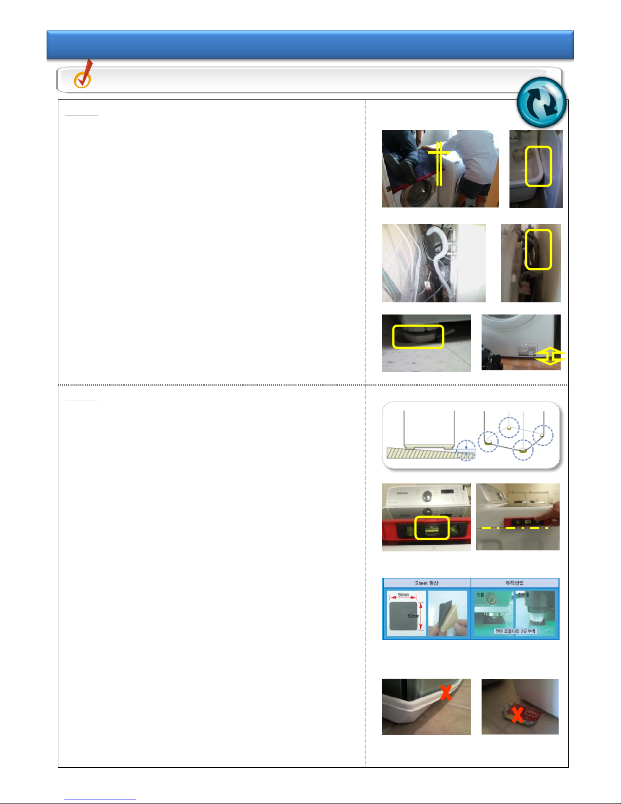
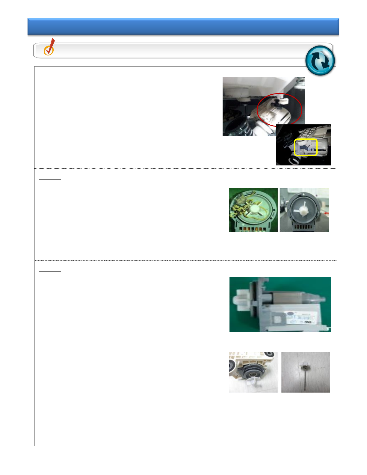
Step 1
①Check the frictional relationship with the
surroundings when installing.
- Install a pair of dryers attached. If frame is shaking
during spinning mode, interference noise is
generated.
②Friction occurs due to unstable shaping of water
supply/drain hose
- Prevent friction between water supply/drain hose and
product or wall.
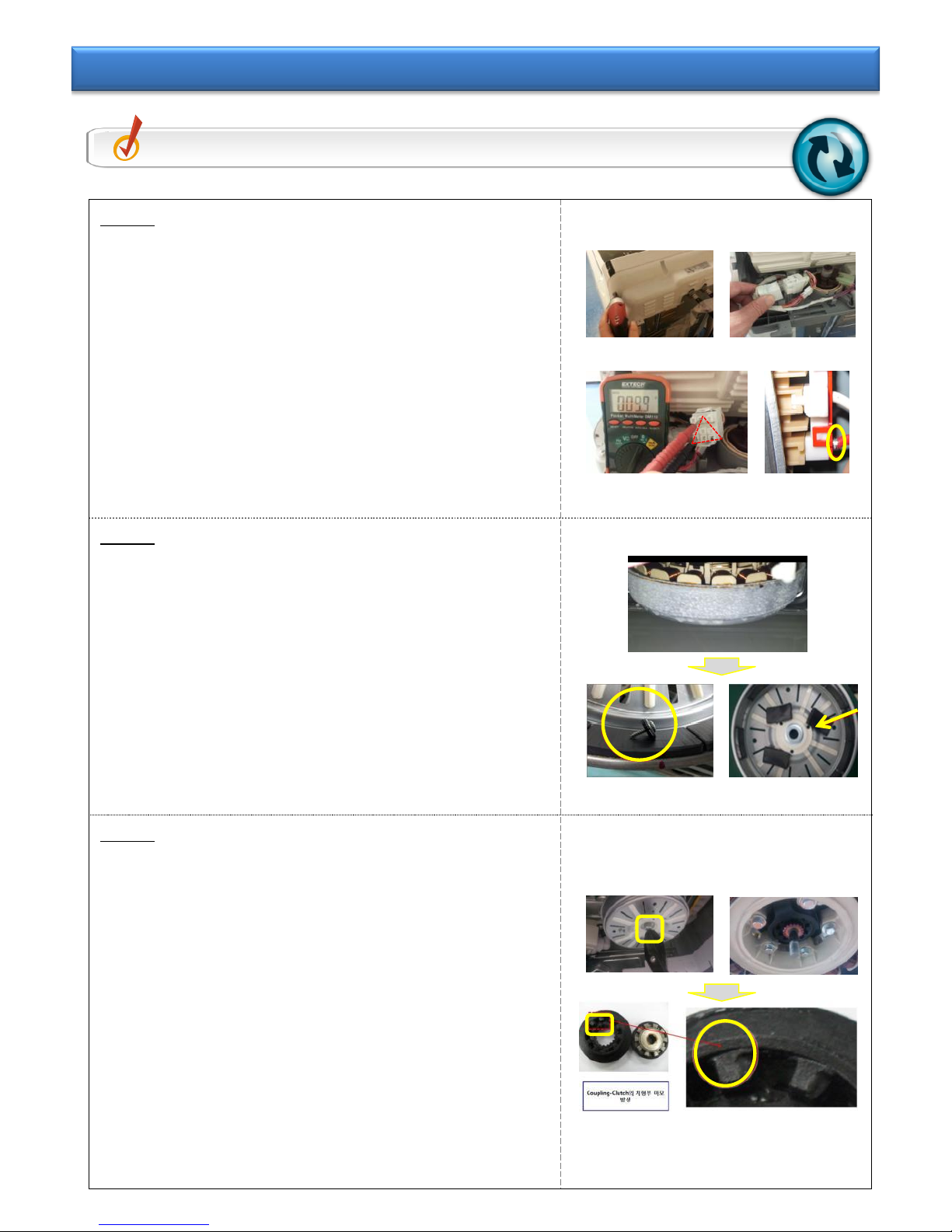
③Floor is shaking, which makes the product move.
Case#1 –Levelness defect due to floor damage.
Case#2 –Shaking due to old laundry room
floor(lumber).
=> It is recommended to contact the installer and request
for re-installation such that it does not influence on
the vibration.
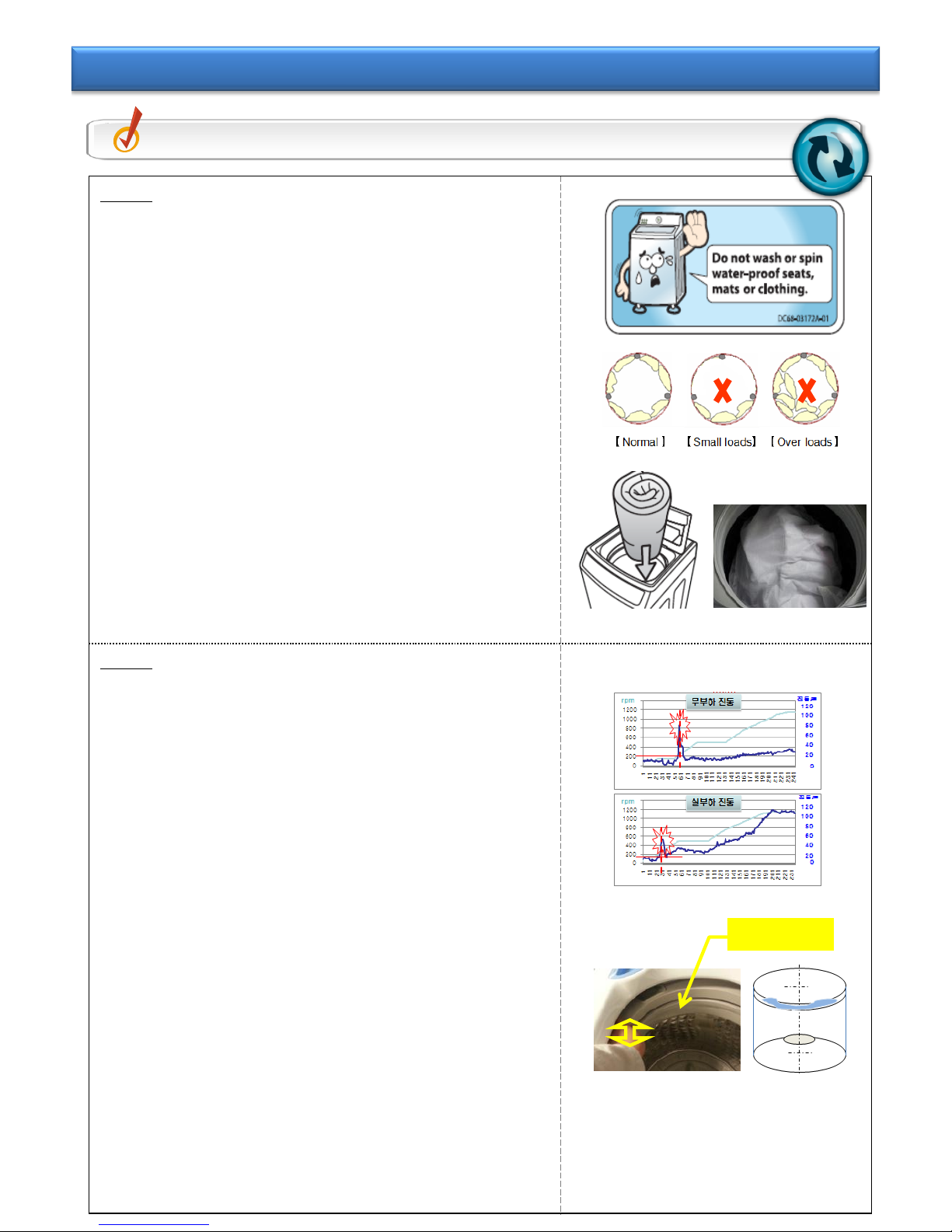
Step 2
①Check the condition of levelness of product
installation.
- For the left and right of product, check the level at
the top of Lid-T/C.
- For the front and rear of product, check the level on
the side of product.
※ When checking the left-and-right level of the product,
Tub is inclined to one side due to tension of Drain-
hose. (During water supply, it is in the right place.)
※ For level installation, adjust Leg to be attached to the
floor.
②Noise from Set on slippery floor (Tile, Moisture)
- Attach Non-Slip Pad to both front legs on the floor.
- Install the front legs of product to be located on the
Non-Slip Pad.
③Inappropriate material of leg for the floor
Case#1 Pan Drain Friction Noise
Case#2 Use paper for floor protection on the Leg
bottom.
=> It is recommended to contact the installer and request
for re-installation such that it does not influence on
the vibration.
Check Point Check the installation place & the condition of unstable installation.
Tip 1-3. Install Place & Unstable Install Abnormality