Hunter Industrial XP 14 User manual

1
INSTALLATION
PROJECT:
LOCATION:
SUBMITTED BY:
FAN MODEL
DOWNROD
WALL CONTROL
VARIABLE FREQUENCY DRIVE
NOTES
*Available upon request.
Fan(s) will be located at the nearest location(s) as per building plans.
Wall control location(s) to be identified by owner at time of installation.
IF INSTALLATION IS TO BE PERFORMED BY OTHERS: Installation and site preparation to be performed by others at owner’s request.
IF GOLD LEVEL INSTALLATION: Basic mechanical installation includes: scissor lift rental (if necessary), mounting all fans and equipment, routing all
communication cables, connecting fans and controls (if applicable) to power supply, and factory authorized startup and commissioning.
**CUSTOMER IS RESPONSIBLE FOR PROVIDING POWER SUPPLY TO 15’ FROM EACH FAN LOCATION PRIOR TO FAN INSTALLATION*
IF PLATINUM LEVEL INSTALLATION: Full turnkey installation includes: routing all electrical wire and conduit from each fan location to electrical
panel, terminating electrical connections with NEMA rated receptacles, scissor lift rental (if necessary), mounting all fans and equipment, routing all
communication cables, connecting fans and control (if applicable) to power supply, routing low voltage fire relay cable from each fan location to security
panel (if fire relay tie-in is required – Customer’s fire/security company to land final connections), and factory authorized startup and commissioning.
DIAMETER
COMMENTS
P: 629.333.7100 | F: 615.232.3891 | TOLL: 1.844.591.FANS (3267) 180 THREET INDUSTRIAL ROAD, SMYRNA 37167 | HUNTERFAN.COM/INDUSTRIAL
24"36"*48"*
To Be Performed By OthersGold Level Installation (Basic Mechanical)Platinum Level Installation (Premium Turnkey)
7'8 '10 '12 '14 '

POWER (hp)
BLDC Motor 5/8 HP
INPUT POWER OPTIONS
CURRENT AT MAX SPEED (Amp)
FAN DIAMETER
FAN WEIGHT
DOWNROD
SAFETY FEATURES
MOUNTING OPTIONS
14 ft (4.3m)
121lbs (55 kg)
I-beam | Direct Mount
Fan Retention System | Airfoil Retention System |Fire relay
2’ Rigid Mount Downrod
MAXIMUM SPEED (RPM)
108 RPM
AC 1PH 100-120V 50/60Hz
6.2 A @ 120v
MAX AFFECTED AREA 70 ft Dia | 4,900 sqft
5”
14’
24”
DIMENSIONS & WEIGHT
POWER & EFFICIENCY
MOUNTING & SAFETY
r092619
OPTIONAL
INCLUDED
CERTIFICATIONS ETL/Intertek-certified to ANSI/UL 507 and CSA
C22.2 No. 113 in North America
Limited Lifetime on Airfoils | 2-year Warranty (parts only)
Rigid Mount with pre-wired downrod | Control Panel | Install Manual | Airfoils
350 Series Fan Controller | Wall Control | Mounting Hardware Kit | Communication Kit
3’ and 4’ Rigid Mount downrod | Additional Control Cable Lengths | Glulam brackets
WARRANTY1
1See complete warranty for details.
430 Series Fan Controller | 700 Series Fan Controller | Environmental Control Solutions
IN THE BOX
WARRANTY & CERTIFICATIONS
XP 14
180 THREET INDUSTRIAL ROAD | SMYRNA, TN 37167 | 1-844-591-FANS | HUNTERFAN.COM/INDUSTRIAL

3
SAFETY & PRECAUTIONS
Important Safety Information
To prevent SERIOUS INJURY, DEATH and PROPERTY DAMAGE, you should read, understand and follow the warnings
and instructions in this manual before installing or operating the fan.
FIRE, ELECTRIC SHOCK and CRUSH HAZARDS.
To prevent SERIOUS INJURY or DEATH:
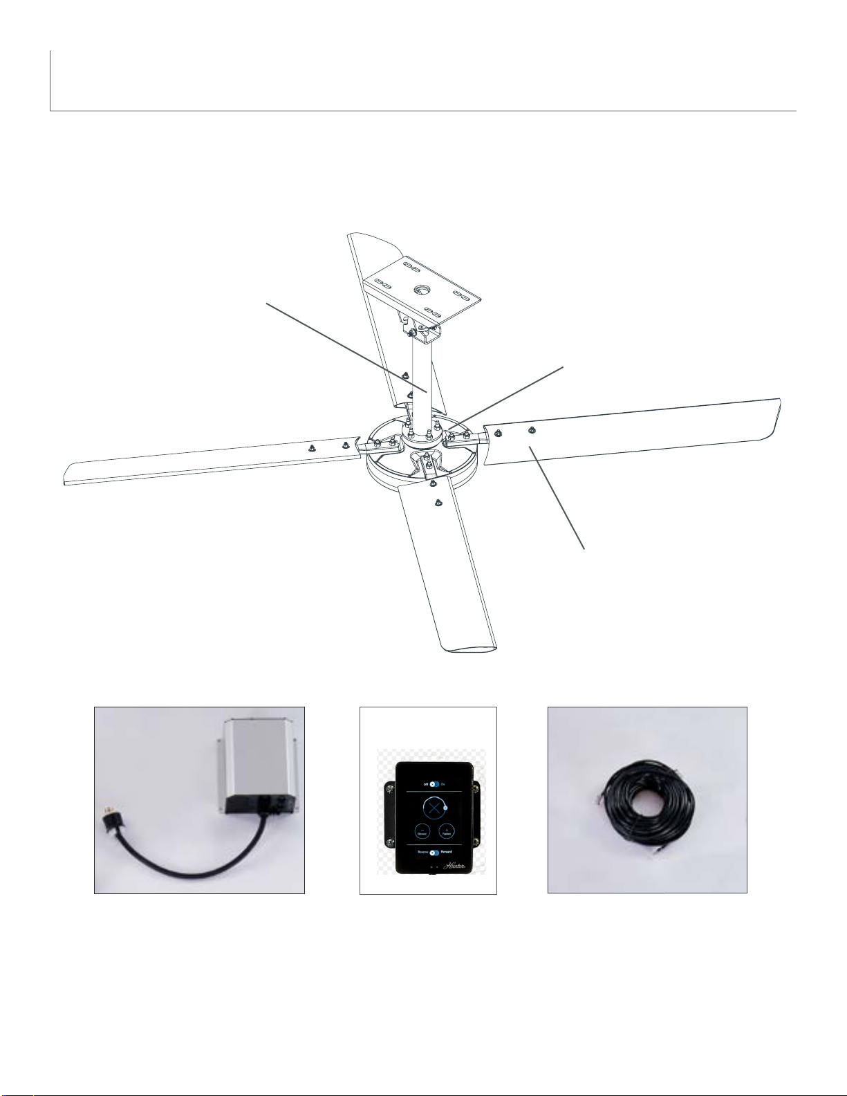
• ALWAYS mount fan directly from building structure that can withstand double the maximum hanging fan weight and
install the Retention Cable.
• BEFORE installing or servicing your fan, ALWAYS disconnect the power by turning off the circuit breaker or
breakers to the fan locations. If you cannot lock the circuit breakers in the off position, securely fasten a
prominent warning device, such as a tag, to the electrical panel.
• All wiring must be in accordance with national and local electrical codes, including ANSI/NFPA 70. If you are
unfamiliar with wiring or in doubt, consult a qualified electrician.
• DO NOT install fan to be used in the presences of flammable vapors and gases or environments where combustible
dust is present.
• DO NOT bend the blades or blade holders when installing or cleaning the fan.
• DO NOT insert foreign objects in between rotating fan blades.
Installation, Adjustment, Repair or Maintenance Must Be Performed By Qualified Personnel.
Follow all safety practices and instructions during the installation, operation and servicing of the fan. Failure to apply these
safety practices could result in death or serious injury. If you do not understand the instructions, please call our Technical
Department at 1-844-593-FANS (3267) for guidance.
Always Check Federal, State and Local Codes Before Installing Fan.
Code compliance is the responsibility of the installer. Check all relevant codes to make sure that all product certifications,
product listings and building regulations are met.
READ AND SAVE THESE INSTRUCTIONS. This manual must always be kept with the fan and should remain
with the fan if it is transferred or sold. Always give manual to fan owner following installation.
Professional installation practice requires following local utility company guidelines for connecting to AC mains.
This unit is for professional use only and is not required to comply with EN 61000-3-2:2006.
This fan conforms to ANSI/UL standard 507, Electric Fans and is certified to CSA STD C22.2 No. 113, Fans & Ventilators.
5007479

4
To prevent serious injury or death:
• BEFORE installing or servicing your fan, ALWAYS disconnect the power by turning off the circuit breaker or
breakers, to the fan locations and confirm Lockout/Tagout procedures are in place. If you cannot lock the circuit
breakers in the off position, securely fasten a prominent warning device, such as a tag, to the electrical panel.
• All wiring must be in accordance with national and local electrical codes, including ANSI/NFPA 70. If you are
unfamiliar with wiring or are in doubt, consult a qualified electrician.
• Do not use extension cord with fan.
• Do not remove covers while power is on.
• Do not use improper voltage source.
All fan controls and incoming power should be installed only by qualified technicians familiar with the requirements of the
National Electrical Code and local codes. Failure to follow these guidelines will void the manufacturer’s warranty.
All electrical controls are configured at the factory and are ready to use. No user adjustments are available. Follow the
included installation instructions when installing this device to ensure proper operation. Do not make any changes to
any part of the fan without first consulting Hunter Industrial Fan. Installation is to be in accordance with ANSI/NFPA 70:
National Electrical Code and local codes.
The user is responsible for compliance with all international and National Electrical Code requirements with respect to
grounding of all equipment. Many of the parts of this unit operate at line voltage.
Before installing, servicing or cleaning the unit, switch power off at the service panel, lock the service disconnecting means
and confirm Lockout/Tagout procedures are in place to prevent power from being switched on accidentally. When the
service disconnect means cannot be locked, securely fasten a prominent warning sign, such as a tag, to the service panel.
To reduce the risk of electric shock, serious injury and death, only use this unit as intended by the manufacturer. I f you
have any questions, call our Technical Department at 1-844-593-FANS (3267).
Electric Shock Hazard
SAFETY & PRECAUTIONS

5
To prevent serious injury or death, ALWAYS attach the Retention Cable to the fan motor and secure to the building structure
on EVERY fan.
The Retention Cable, if installed per Hunter Industrial Fan specifications, can limit the distance the fan could fall in the
unlikely event of mounting system failure. Failure to install and to secure the Retention Cable will void your warranty.
Mark the Floor to Alert Personnel
When mounting a fan in an area where materials could be elevated and contact the rotating fan blades,
mark or paint the floor with a large crosshatched circle, similar to the figure to the left, to alert personnel of
the overhead fan locations.
Weight and Torque Considerations
Always mount fan directly to building structure that can withstand approximately double (2x) the maximum hanging weight
of the fan.
The hanging weight of a 14’ fan with a standard 2’ downrod is 121 lbs.. The maximum hanging weight of a 14’ fan with a
4’ downrod is 135 lbs and a maximum torque of 75 ft lbs.
If there is any uncertainty about the potential for the building structure to withstand double the maximum hanging weight
of the fan, a professional structural engineer should perform a thorough evaluation of the building prior to purchasing
the fans. Hunter Industrial Fan provides guidelines for mounting fans; however, it is the sole responsibility of the building
owner and installer to ensure the safety of the mounting system and Retention Cable, the building structure is sound and
the installation complies with all federal, state and local codes.
Damaged Equipment
Never operate or install any fans or fan accessories that appear to be damaged. Failure to follow this instruction can result
in death, serious injury or equipment damage.
To reduce the risk of personal injury, do not bend the blades or blade holders when installing or cleaning the fan.
Do not insert foreign objects in between rotating fan blades.
Service
If the fan does not operate properly using the procedures in this manual, remove all power to the unit and contact our
Technical Department for further assistance at 1-844-593-FANS (3267).
Always Use Personal Protective Equipment
You should always wear Personal Protective Equipment, such as a Hard Hat, Safety Glasses and a Fall Harness when
installing Industrial fans.
CRUSH HAZARD
SAFETY & PRECAUTIONS

6
FAN PLACEMENT
ALWAYS mount fan so the bottom edge of blade to the floor is at least 10 feet from the floor and at
least 25% of fan diameter from the ceiling.
Always mount fans away from the following:
Sprinkler Systems
Prior to installing fans, review all codes applicable to sprinkler systems and fans to ensure code compliance and refer
to NFPA 13: Fire Sprinkler System Installation. In any installation where fire sprinklers are present, the fan should not
interfere with their operation.
o Fans should be located at least 3 feet below a sprinkler deflector.
o Fans should be centered between 4 adjacent sprinklers.
o The Industrial Control Panel should be connected to a fire relay system, which can stop the fans in the event a fire
occurs.
It is your responsibility that the installation complies with the applicable codes. For assistance, please call our Technical
Department at 1-844-593-FANS (3267).
Walkways and Mezzanines
If the building has elevated walkways or mezzanines, mount the fans so that a person cannot reach the rotating blades in
any way. Position fans so that the tips of the blades are at least 5 feet away from any area where a person may be able to
extend outward to reach them.
Lights and Skylights
If possible, avoid mounting fans directly below lights or skylights to avoid any strobe effect caused by moving blades.
There should be a minimum of 2 feet between the blades and any light fixture.
Air Discharge Locations
Fans should not be located directly beneath any air discharge. This includes air conditioning units and evaporative coolers.
Such equipment can be used effectively in conjunction with high-volume low-speed (HVLS) fans however the discharge of
the unit must be located outside the swept area of the fan and at a distance of at least two times the diameter.
Windy Locations
Do not operate or install fans in outdoors or in areas exposed to wind. Failure to follow this instruction can result in death,
serious injury or equipment damage.
Wet Locations
DO NOT locate fans where they may come into direct contact with water. These fans are suitable for mounting in damp
locations.
Other HVLS Fans
See the chart on the following page to determine proper spacing between adjacent fans.

7
FAN PLACEMENT
2 FT
Min
2 FT
Min
20-25% OF
FAN DIAMETER
MINIMUM CLEARANCE
FAN PLACEMENT
FAN SPACING CHART
A
MIN - MAXDIA
A B
XP
35ft - 56ft
(10,67m - 17,07m)
14ft
(427cm)
10ft
(305 cm)
12ft
(366cm)
8ft
(244 cm)
7ft
(213 cm)
25ft - 40ft
(7,62m - 12,19m)
30ft - 48ft
(19,14m - 14,63m)
20ft - 32ft
(6,10m - 9,75m)
18ft - 28ft
(5,49m - 8,53m)
B

8
MAINTENANCE
Electric Shock Hazard
To prevent serious injury or death:
• BEFORE performing maintenance or service, ALWAYS disconnect the power by turning off the circuit
breaker or breakers to the fan locations and confirm Lockout/Tagout procedures are in place.
• If you cannot lock the circuit breakers in the off position, securely fasten a prominent warning
device, such as a tag, to the electrical panel.
• Do not remove covers while power is on.
Blade Cleaning
Depending on the commercial application, dust or other particulates can build up on the fan blades
over time. At least every 12 months, a maintenance person or skilled trade professional, who has
experience using a lift, should clean the blades using a rag or sponge and hot water or regular
cleaning solutions.
DO NOT use chlorine or any chemicals containing chlorine, or the blades may be damaged.
Retention System Check
Each fan is installed with a retention system. Every 12 months, check that the Retention Cable is
properly attached to the building structure. Inspect the visible portions of the Retention Cable for
damage, including fraying.
The Retention Cable is an important part of the safety system and protects users in the
unlikely event of a catastrophic situation. It is critical for fan owners to ensure that it is intact and
properly secured.
Replacement Parts
Please call 1-844-593-FANS (3267) for replacement parts.
Service
If the fan does not operate properly using the procedures in this manual, follow Lockout/Tagout
procedures for your facility and lockout all power to the unit and contact our Technical Department for
further assistance at 1-844-593-FANS (3267).
Electric Shock Hazard

9
IN THE BOX
FAN COMPONENTS
A
B
C
A (1) Downrod
B (1) Motor
C (4) Blades
D (1) Control Panel
E (1) Standard Control
F (1) Communication Cable
G (1) Installation Manual (not shown)
DEF

10
STANDARD CONTROL
350 SERIES TOUCHSCREEN CONTROLLER
• Comes standard on XP and Eco Fans
• Simple control of speed and direction
• Can be daisy chained to control up to 5 fans
• 3.5” LCD Touchscreen
• Alert Readouts
• Plug-n-Play design
• Standard junction box
• Simple flush mounting
[2.73]
69.31
[2.00]
50.80
[3.95]
100.31
[3.05]
77.44
[3.55]
90.14
[0.203]
4 places
5.16
[2.06]
52.26
180 THREET INDUSTRIAL ROAD | SMYRNA, TN 37214 | 1-844-591-FANS (3267) | HUNTERFAN.COM/INDUSTRIAL

CONTROL
• Compatible with all Hunter Industrial Fans
• Simple intuitive user Interface
• Standard on Titan
• Password protection for scheduling,
grouping, and fan naming
• BMS Integration with optional gateway
• Fan diagnostics directly from screen
• Most cost effective network controller
NUMBER OF FANS CONTROLLED
ACTIVE DISPLAY AREA
RESOLUTION
DIMMING
PROTECTION CLASS
INPUT VOLTAGE
UP TO 10 FANS
4.3” DIAGONALLY
480 X 272 DIAGONAL
DIMMABLE TO 0%
IP66
100 VAC - 240 VAC
4.3”
TOUCHSCREEN
430 SERIES TOUCHSCREEN CONTROLLER
[4.30]
109.31
[5.88]
149.31
UP TO 10 FANS
[3.59]
91.20
180 THREET INDUSTRIAL ROAD | SMYRNA, TN 37214 | 1-844-591-FANS (3267) | HUNTERFAN.COM/INDUSTRIAL
11

12
700 SERIES TOUCHSCREEN CONTROLLER
• Optional Environmental Control
• BMS Integration with optional gateway
• Control up to 30 fans with network solutions to
fit your needs
• Password protection for scheduling, grouping,
and fan naming
• Fan diagnostics directly from screen
NUMBER OF FANS CONTROLLED
ACTIVE DISPLAY AREA
RESOLUTION
DIMMING
PROTECTION CLASS
INPUT VOLTAGE
UP TO 30 FANS
7” DIAGONALLY
480 X 272 DIAGONAL
DIMMABLE TO 0%
IP66
100 VAC - 240 VAC
700
TOUCHSCREEN
[5.18]
131.60
[7.69]
195.20
[4.04]
102.70
CONTROL
180 THREET INDUSTRIAL ROAD | SMYRNA, TN 37214 | 1-844-591-FANS (3267) | HUNTERFAN.COM/INDUSTRIAL

OPTIONS FOR CONTROLS
13
BACNET GATEWAY
•
•
Simple approach to
interface fans to a Building
Management System
Enables remote monitoring,
control and visualization of a
fan network
• Supports BACnet MS/TP and
BACnet/IP
IP67
BTL | CE | FCC CLASS B&C PART 15 | UL 60950
IC CANADA | ROHS AND WEEE COMPLIANT | PTCRB AND CTIA
OPERATING ENVIRONMENT TEMPERATURE
OPERATING ENVIRONMENT HUMIDITY
INPUT VOLTAGE
ENCLOSURE RATING
CERTIFICATIONS
-20° TO 70°C/(-4° TO 158°F)
10-95% RH NON-CONDENSING
24VAC 125MA, 12-24VDC 250MA @ 12VDC
BACNET GATEWAY
180 THREET INDUSTRIAL ROAD | SMYRNA, TN 37214 | 1-844-591-FANS (3267) | HUNTERFAN.COM/INDUSTRIAL

CONTROL CABLE REPEATER
•
•
Extend standard Cat 5e/Cat
6 Ethernet cable runs an
additional 100M without loss
of transfer speed
Port Speed: 10/100 Mbps
auto detect 3W
IP67
IEEE 802.3I, 802.3U, 802.3X FOR 10/100 ETHERNET
IEEE 802.3AB, 802.3X FOR GIGABIT ETHERNET
CE | CSA | EICC | UL E200031 | ROHS 2 COMPLIANT
OPERATING ENVIRONMENT TEMPERATURE
OPERATING ENVIRONMENT HUMIDITY
INPUT VOLTAGE
MAX POWER
ENCLOSURE RATING
CERTIFICATIONS
-40° TO 75°C (-40° TO 167°F)
10-95% RH NON-CONDENSING
CLASS 2 POWER SUPPLY: 12-48VDC, 18-30VAC 50/60HZ
BACNET GATEWAY
OPTIONS FOR CONTROLS
14
180 THREET INDUSTRIAL ROAD | SMYRNA, TN 37214 | 1-844-591-FANS (3267) | HUNTERFAN.COM/INDUSTRIAL

15
ELECTRICAL
Do not use an extension cord with fan.
Do not remove covers while power is on.
Do not use improper voltage.
Breaker Size Chart
Electrical Plug Requirements
Voltage
110-120V L5-15RL5-15P
Plug Receptacle
A Plug and Receptacle are included with each fan.
XP AMP DRAW
Fan Diameter AC 1PH 100-120V 50/60Hz Recommended Breaker Size
14’ 7.5A - 6.2A 10A
12’ 8.4A - 7A 15A
10’ 9.1A - 7.6A 15A
8’ 5.2A - 4.2A 10A
7’ 6.7A - 5.5A 10A

FIRE PANEL (FIELD WIRING)
16
DRY CONTACTS: NORMALLY CLOSED
S
C
C
SA
FIRE RELAY
SB
-
+
12 - 40VDC
•On the Terminal Strip mounted to the outside of the VFD enclosure a
Jumper will be in place on terminals “S” and “C”. Remove the Jumper from
terminals “S” and “C”.
•Connect the wires coming from the Fire Panel to terminals “S” and “C”.
NORMALLY UNENERGIZED
S
C
C
SA
FIRE RELAY
SB
-
+
12 - 40VDC
•On the Terminal Strip mounted to the outside of the VFD enclosure a
Jumper will be in place on terminals “S” and “C”. Remove the Jumper from
terminals “S” and “C”.
•Connect a wire from terminal “S” to “SB” on the Fire Relay Terminal Strip
•Connect a wire from terminal “C” to “C” on the Fire Relay Terminal Strip.
•Apply 12-40VDC from Fire Panel to Fire Relay Input. Relay has a 20mA
draw.
NORMALLY ENERGIZED
•On the Terminal Strip mounted to the outside of the VFD enclosure a
Jumper will be in place on terminals “S” and “C”. Remove the Jumper from
terminals “S” and “C”.
•Connect a wire from terminal “S” to “SA” on the Fire Relay Terminal Strip.
•Connect a wire from terminal “C” to “C” on the Fire Relay Terminal Strip.
•Apply 12-40VDC from Fire Panel to Fire Relay Input. Relay has a 20mA
draw.
S
C
C
SA
FIRE RELAY
SB
-
+
12 - 40VDC
180 THREET INDUSTRIAL ROAD | SMYRNA, TN 37214 | 1-844-591-FANS (3267) | HUNTERFAN.COM/INDUSTRIAL

FIRE PANEL (FIELD WIRING)
180 THREET INDUSTRIAL ROAD | SMYRNA, TN 37214 | 1-844-591-FANS (3267) | HUNTERFAN.COM/INDUSTRIAL
FIRE RELAY ARRANGEMENT FOR MULTIPLE FANS (30 FAN MAXIMUM)
Normally Energized/Unenergized
Dry Contacts
VFD Enclosure
without Fire Relay
VFD Enclosure
without Fire Relay
VFD Enclosure
without Fire Relay
VFD Enclosure
with Fire Relay
Fire Panel
10-40VDC
VFD Enclosure
without Fire Relay
VFD Enclosure
without Fire Relay
VFD Enclosure
without Fire Relay
VFD Enclosure
without Fire Relay
Fire Panel
Normally
Closed
17

18
XP 14
2'-0"
14'-0"
0'-5"
14'.0
Table of contents
Other Hunter Industrial Fan manuals
Popular Fan manuals by other brands

BLAUBERG Ventilatoren
BLAUBERG Ventilatoren Omega Series user manual

MOORE FANS
MOORE FANS AirBrake installation instructions

Vent-Axia
Vent-Axia 496575 Installation and wiring instructions

Hunter
Hunter Symphony manual

Mitsubishi Electric
Mitsubishi Electric Lossnay VL-220CZGV-E manual

Dimplex
Dimplex DXL 100 Installation and maintenance instructions

Martec
Martec SCORPION DC Series installation guide

Helios
Helios MiniVent ultra Silence M1/150 0-10 V Installation and operating instructions

Thermador
Thermador PROFESSIONAL VCIN36JP Use and care guide

Fanimation
Fanimation FPD7916 owner's manual

Ego Power+
Ego Power+ FN1800E manual

Vent-Axia
Vent-Axia Lo-Carbon Revive Series Installation and wiring instructions