Huntron Shortrack 90 User manual

Huntron Shortrack model 90 User’s Manual (part no. 21-1186);
Rev 1, 1/98
INTRODUCTION
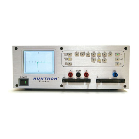
The Huntron SHORTRACK Model 90 is a short locating accessory for the Tracker line of Analog
Signature Analysis (ASA) instruments. A Tracker can detect that there is a low impedance fault
on a certain node of a PCB but it cannot always locate where the fault is. The SHORTRACK is
designed to pick up and give an indication of the current flowing through the fault so that it can
be followed and located.
The SHORTRACK can be used with the LOW range of the Tracker 1000, Tracker 2000 or
Tracker 5100DS. It is powered by a 9 Volt battery and has a LCD display with a fast responding
analog bargraph and a digital readout. An inductive probe is used to trace current flow in the
PCB.
HOW TO USE THE SHORTRACK
This section explains how to use your instrument. Topics included are:
- Description of physical features and their operation
- Setup procedure
-Application examples
Features
This section describes the features of your instrument. Refer to the figure below.
Display:
The display is an LCD which consists of an analog display and a digital display:
The Analog Display is a 101 segment bargraph that simulates a meter movement. It is elliptical
in shape to allow the large number of segments to be displayed. The bargraph responds quickly
to signal changes and it can be understood directly so this is the primary means of tracing
current with the SHORTRACK.

The Digital Display is a three digit numeric display that is used to adjust the gain properly and
also to interpret relative current readings. The numeric display is capable of 999 counts but in
normal operation readings will be between 50 and 150. The maximum "useful" reading is 100
counts which corresponds to full scale on the analog display.
When the battery is low, all three decimal points turn on to show that you have at least 50 hours
of operation left. The decimal points are not used in normal operation since the display has a
resolution of 1 count = 1%. When the instrument power is turned on the display will go full scale
once or twice; this is normal operation as the circuit settles.
GAIN Control:
This is used to adjust both analog and digital displays to 100% while the probe monitors a
reference current.
POWER Switch:
This switch turns the instrument ON and OFF.
Probe Receptacle:
This connector is for the current probe.
Setup
1. Select the LOW range on the Tracker.
NOTE: The SHORTRACK is designed to be used with the LOW range of any Tracker. All other
Tracker ranges do not provide enough current to give meaningful readings.
2. Connect the Tracker to drive current into the short on the PCB. Make sure the Tracker leads
are not draped across the PCB so that the probe only picks up magnetic fields that are on the
PCB.
3. Plug the current probe into the receptacle on the front panel.
4. Turn the power on and hold the instrument in your left hand so that you can adjust the GAIN
control with your thumb.
5. Hold the current probe in your right hand and place it over the maximum current point (see
figure below). This is a trace on the PCB that has all the Tracker current flowing through it.

6. Align the probe for best sensitivity by orienting the wide part of the tip perpendicular to the
PCB trace. Also keep the probe body perpendicular to the PCB as shown in the following figure.
7. While holding the probe steady, adjust the GAIN control until the display reads 100%. This
completes the setup.
The SHORTRACK will now give an approximate indication of the relative amount of current (with
respect to 100%) that is flowing in any trace that the probe is placed on. When looking for an
actual fault, you use the probe to follow the current by locating a trace that gives a reading of 90-
100%. As you move the probe along the trace, the reading will drop to zero when you pass the
short or the current branches off into another trace. If there is no other physical branch where the
reading goes to zero, inspect that location for the fault that is causing the short.
Applications
Now that you have a basic idea of how to use the SHORTRACK, we will provide several
examples covering various types of low impedance faults.
Hard Shorts (less than 1ohm)
The Tracker shows a vertical line for hard shorts which is the same signature you get when you
short the Tracker leads together.
PCB Defect Example:
Using the Tracker, you have found a hard short between points A and N on the PCB shown in
the figure below.
Follow this procedure to locate the fault:
1. Connect one of the Tracker test terminals to point A on the PCB by using a "grabber" type test
clip on one lead of R12.

2. Connect the other Tracker test terminal to point N on the PCB by using a test clip on one lead
of C5.
3. Make sure the Tracker is set to the LOW range.
4. Place the probe at point B and align properly. This is a maximum current point for this circuit.
5. Turn the GAIN knob until the display reads 100%.
6. Short location: move the probe to different points along the upper trace and observe the
SHORTRACK readings:
At C the reading is the same as B because the same current is flowing there (100%).
At D the reading is zero because that branch trace is not carrying current to the short.
At E, F, and G the reading is the same as B and C. At H the reading goes to zero because you
have passed the short.
7. By checking the trace carefully between points G and H you can find the cause of the short.
8. If you had started at point N, then points M, L, K and J would all read 100% and point I would
be zero indicating that the short is between J and I.
Since there are no components present at the location of the short, this example is most
indicative of a copper bridge that can occur during manufacture of the PCB. Cutting the area
between the two traces can remove the short and restore the proper signature that should exist
when the Tracker leads are connected to
the two traces.
Backplane Example:
A common problem in a manufacturing environment is a solder bridge between adjacent pins of
a device. In this example you have detected a short between two adjacent traces on the
backplane PCB shown in the following figure.
Use this procedure to isolate the shorted connector:
1. Connect the Tracker leads to the shorted traces using the pins on the connector to the LEFT
of point A.
2. Place the probe at point A and use GAIN to adjust the display to 100%. This may take a higher
setting on GAIN than the previous example because the magnetic field of the adjacent trace will
tend to cancel the field of the first trace. Make sure the center of the probe is directly over the
trace you are measuring.
3. Move the probe to B. This will still read 100% so the short is not between A and B.
4. Move the probe to C. Again the reading will be 100% so the short is not between B and C.
5. Move the probe to D. The reading will drop to zero because the shorted pins are on the
connector between C and D. In a real case you would turn the PCB over and look for a solder
bridge or even a bent pin on that connector.

Component Shorts (1ohm - 20ohm)
When a component fails and causes a low impedance fault, it will usually not be as low in
resistance as the previous hard short examples. The Tracker may show a significant angle
between the signature and the vertical axis on the CRT display.
IC Short Example:
The figure below shows several ICs that have a common enable control, EN1. You have found a
10 ohm short between EN1 and GND using the Tracker. The procedure to find the fault is similar
to the backplane example above.
Procedure:
1. With the Tracker LOW range connected to EN1 and GND, place the current probe over point
A.
2. Align the probe and adjust GAIN for a reading of 100%.
3. Probe point B. The reading will be 100% so all the current at point A is still flowing at point B.
4. Probe point C. The display will drop to zero because point C is past the fault. U2 is the suspect
IC and you can verify that current is flowing through it by putting the probe on top of U2. This will
show a fairly strong reading (40-60) whereas the other ICs will give zero readings.
Low Resistance Capacitor Example:
One failure mechanism for electrolytic capacitors is when the dielectric fails and the plates
become shorted. Typically the capacitor will be in parallel with other capacitors (e.g. across a
power supply) and it is not clear from the Tracker signature which one is the problem. Capacitors
in parallel are shown in the following figure.

The short locating procedure is the same as the last two examples. There is one additional step,
however, if you are using a Tracker 2000: select the 50/60 Hz test frequency. This makes the
impedance of the individual good capacitors as high as possible which minimizes the amount of
current diverted into the good components. If this diverted current is negligible the readings will
be 100% at points A, B, C and D. With no path beyond C4, it must be the faulty capacitor.
Conversely, if the diverted current is not negligible you may see the current readings go 100% -
98% - 95% - 93% at points A, B, C and D. This would still indicate that most of the current is
flowing in C4.
General Comments
When the reading drops to zero on a double-sided or multi-layered PCB, you need to check if the
signal died after passing a via or component pad. If it does, the current to the short is now
flowing on the other side of the board or in an inner layer. Turn the board over so that you can
continue to follow the trace or turn up the GAIN so you can follow the inner layer trace. When a
multilayer board has a short between the power and ground planes, the current "spreads out" and
since it is not concentrated in a PCB trace the magnetic field will probably be too weak for the
SHORTRACK to detect. Keep the leads from the Tracker connected to the PCB at points roughly
1 inch (25cm) apart. If you move the Tracker leads around to various points across the same
short, you may find a point where the SHORTRACK gives no response outside an area right
around the Tracker leads. In that case the fault must be within that area. In other words you may
not pick the best location for connecting the Tracker leads to the PCB the first time; moving the
Tracker leads around can be a normal part of short location.
MAINTENANCE
Repairs or servicing not covered in this manual should only be performed by qualified service
personnel as described in the HUNTRON SHORTRACK Model 90 Service Manual (contact
Huntron for availability).
General Maintenance
To clean the instrument, wipe the case with a damp cloth and mild detergent (do not use
abrasives or solvents) and avoid getting water inside the case. When the instrument is not in
use, store it indoors in a dry place.
Calibration
The SHORTRACK does not require periodic calibration for proper operation. There is a ZERO
adjust inside that is factory set to produce a 0 ohm +/-3 counts average reading with zero signal
(probe away from any AC magnetic field). This adjustment should not require any attention.
Battery Replacement
The instrument is powered by a single 9 Volt battery (NEDA 1604, 6F22 or 006P). Use the
following procedure to replace the battery:
1. Remove the current probe from the front panel receptacle.
2. The case bottom is secured to the case top by four screws. Using a #1 Phillips-head
screwdriver, remove the four screws from the case bottom and lift off the case bottom.
3. Lift the old battery out of the battery holder and insert a new battery into the battery holder.
4. Replace the case bottom and reinstall the four screws.
Probe Test
Use the following tests to verify the integrity of the current probe:
1. Continuity Test - measure the resistance between pins 1 and 3 of the probe jack. You should
read 16ohms +/- 20% if the electrical path through the inductor is intact.
2. Inductance Test - if you have access to a LCR meter, use it to measure the inductance
between pins 1 and 3 of the probe jack. You should read 220mH +/-20%.

Service
If the instrument fails, check the battery and replace as needed. Also check the probe as
previously described. If the instrument still does not work properly, service is required. For
factory service in the United States, call (toll-free) 800-426-9265 to describe the malfunction and
obtain an RMA number and shipping instructions prior to shipment. This number must be clearly
displayed on the exterior of the shipping carton.
Only parcels displaying an RMA number will be accepted. In Washington state, call
425-743 3171. Huntron is also accessible bye FAX at 425-743-1360, by e-mail at
info@huntron.com, and on our Internet Home Page at http://www.huntron.com. Pack the
instrument securely in its original shipping container and ship it, postage paid, to Huntron
Instruments, Inc. at the address given in the front of this manual. Outside the United States,
contact your local distributor for service. Please include a description of the malfunction. An
instrument under warranty will be promptly repaired or replaced (at Huntron's option) and
returned at no charge. See the front of this manual for warranty terms. If the warranty has
lapsed, the instrument will be repaired and returned for a service fee. Contact Huntron for prices.
SPECIFICATIONS
Signal Source: LOW range of a Huntron Tracker
open circuit voltage:<_>10 Volts peak
short circuit current:<_>132mA RMS
Frequency Response: 50Hz to 2000Hz
Sensitivity: Display can be adjusted to 100% with current flow caused by a 20ohm resistance
across LOW range.
Display: Analog:101 segments, updates 25/sec
Digital:999 counts, updates 2.5/sec
Readout is proportional to detected magnetic field strength.
Operating Temperature: 0C to 50C
Storage Temperature -20C to 60C
Relative Humidity: 0% to 50%
Battery Type: 9V, NEDA 1604 or 6F22 or 006P
Battery Life: 400 hours typical with alkaline
Shock, Vibration: Will withstand shock and vibration encountered in commercial shipping
and handling.
Size (HxWxL): 1.5 in x 3.2 in x 5.6 in (3.8 cm x 8.1 cm x 14.2 cm)
Weight: 8.0 oz (230 g)
Table of contents
Other Huntron Circuit Tester manuals