HYCON HED User manual

HED
Handheld Earth Drill
HYCON A/S
Juelstrupparken 11
DK-9530 Støvring
Denmark
Tel: +45 964 5200
Fax: +45 964 5201
Mail: hycon@hycon.dk
www.hycon.dk

1
Contents
Side
Safety Precautions.............................................................................................. 2
Oil Flow and Pressure ......................................................................................... 4
Technical Data ................................................................................................... 5
Service and Maintenance .................................................................................... 6
Oil Types ........................................................................................................... 6
Fault Location ....................................................................................................
Dismounting of Main Components ....................................................................... 8
Mounting of Earth Drill..................................................................................... 10
Tool List ...........................................................................................................18
Spare Parts List .................................................................................................19

2
1. Safety Precautions
•The earth drill must always be operated by two operators.
•The operators must pay extra attention and show caution when working in
difficult working areas, such as slopes and other dangerous nature of the ground.
Do not reach too far with the earth drill, but always maintain a good footing and
keep your balance.
•The operators must always use protective goggles, earplugs, hard hat and shoes
when operating the earth drill.
•The operators must be properly trained in using the earth drill or under
supervision of a qualified instructor.
•A fine jet of oil at pressure can penetrate the skin. It is therefore important never
to use your fingers to check for oil leaks and never to hold your face close to su-
spected leaks – use a piece of cardboard instead. If oil has penetrated the skin,
you should get medical treatment immediately.
•Never leave the earth drill, when it is connected to the powerpack.
•Use only original HYCON augers.
•Always use approved hoses. Contact your dealer if necessary. Be careful to mount
the hoses correctly. The earth drill is marked with “P” and “T”, and “P” should be
connected to pressure and “T” to tank.
•Never use the earth drill close to electric cables. Prior to operation, check if there
are hidden or buried cables.
•The earth drill is mounted with a pressure relief valve (torque limiter). It has been
adjusted to 90 bar from the factory and may never be changed as this may cause
severe personal injury.

3
•Never wear loose clothing as it may get entangled in the moving parts of the
earth drill.
•Inspection or cleaning of the earth drill, change of auger or disconnection of
hoses may never be done while the earth drill is connected to the powerpack, as
unintentional activation of the earth drill can cause severe damage.
•Always connect hoses to the earth drill before starting the powerpack. Be sure
that all couplings are tight.
•The earth drill may not be operated if the oil temperature is above 0 C°.
Operation at higher temperatures may result in the earth drill getting warmer
than normal and the operators risk getting burnt on it.
•To avoid all personal injury and damage to material, all repair, maintenance and
service work must be carried out by authorized or properly trained persons only.
•An earth drill not in use should always be kept in a safe and dry place.
•Do not try to do a job with an earth drill that is too small for the job.
•Always make sure that the labels and warning signs on the earth drill are legible.
•Always use hoses, couplings and spares as such recommend by HYCON A/S.
•Repairs may only be carried out by experienced personnel.
•Make sure that all couplings are cleaned before connection.
•Always disconnect the hydraulic circuit before connecting or disconnecting the
earth drill. If this is not done, there is a risk of damage to the quick release coup-
lings or the hydraulic system getting superheated.
IMPORTANT

4
. Oil Flow and Pressure
Your new HYCON earth drill is designed for a certain oil flow, working pressure and
maximum pressure. A too high oil flow and/or a too high pressure results in overload
of the earth drill, meaning that the lifetime of your new HYCON tool will not be as
expected, and that your service and repair costs will be too high.
It is important to check that the earth drill is not supplied with an oil flow beyond its
design capacity, that the working pressure is correct and that the maximum allowed
pressure is not exceeded.
On page 5 you will find the technical data.
The earth drill is mounted with a pressure relief valve (torque limiter). This has been
adjusted to 90 bar from the factory and may not be changed, as it can cause severe
personal injury.

5
3. Technical Data
Weight 19.6 kg (43.2 lbs)
EHTMA category C/D
Oil flow 20-40 l.p.m. (5-10 g.p.m.)
Working pressure nominal 80 bar (1200 psi)
Built-in torque limiter
(pressure relief valve) 90 bar (1300 psi)
Max. setting of pressure relief
valve on power source 210 bar (3100 psi)
Max. return pressure 5 bar (1100 psi)
Max. torque 250 Nm (180 lbf-ft)
Max. oil temperature 0° C
Vibration level < 2.5 m/s² (128 dB)
Sound pressure level L
PA
1 m 91 dB
Guaranteed sound power level L
WA
100 dB

6
4. Service and Maintenance
Service/Maintenance Daily Weekly Yearly
Check couplings and clean carefully X
Check hoses X
NB. At service/repair it is important to mount the quick-release couplings correctly.
Mount the female coupling at “P” and the male at “T”.
Oil Types
The HYCON earth drill uses standard hydraulic oil, i.e. all types of mineral oil and
biodegradable oil, which comply with the following values:
Recommended viscosity 20-40 cSt
Permitted viscosity 15-1000 cSt
Viscosity index Min. 100
Temperature area -20° to + 0° C
If using biodegradable oil, we recommend the use of oil based on rape. Other types
of oil can be aggressive towards the seals. If you are in doubt, please ask your
dealer.

7
6. Fault Location
Problem Cause Solution
Pressure relief valve may be
clogged up or defective
Dismount pressure relief valve
and clean with compressed
air, or replace the valve
Earth drill is difficult to hold,
keeps turning
Wrong adjustment of
pressure relief valve
Adjust pressure relief valve
correctly
Hydraulic oil is leaking at
the valve block
Worn seals in the seal
housings on the valve block
Replace worn seals.
See section 8
Earth drill does not start to
drill, even though the
trigger lever is fully
activated
Wrong adjustment of
threaded rod between trigger
lever and trigger
Adjust threaded rod between
trigger lever and trigger.
See section 8
Earth drill does not rotate
forwards/reverse
Wrong adjustment of
threaded rod between trigger
lever and trigger
Adjust threaded rod between
trigger lever and trigger.
See section 8
Dirt in pressure relief valve Dismount pressure relief valve
and clean with compressed
air
Wrong adjustment of
pressure relief valve
Adjust pressure relief valve
correctly
Earth drill does not work
satisfactorily, or
performance is too weak
Power source performance is
too low
Check the power source
8
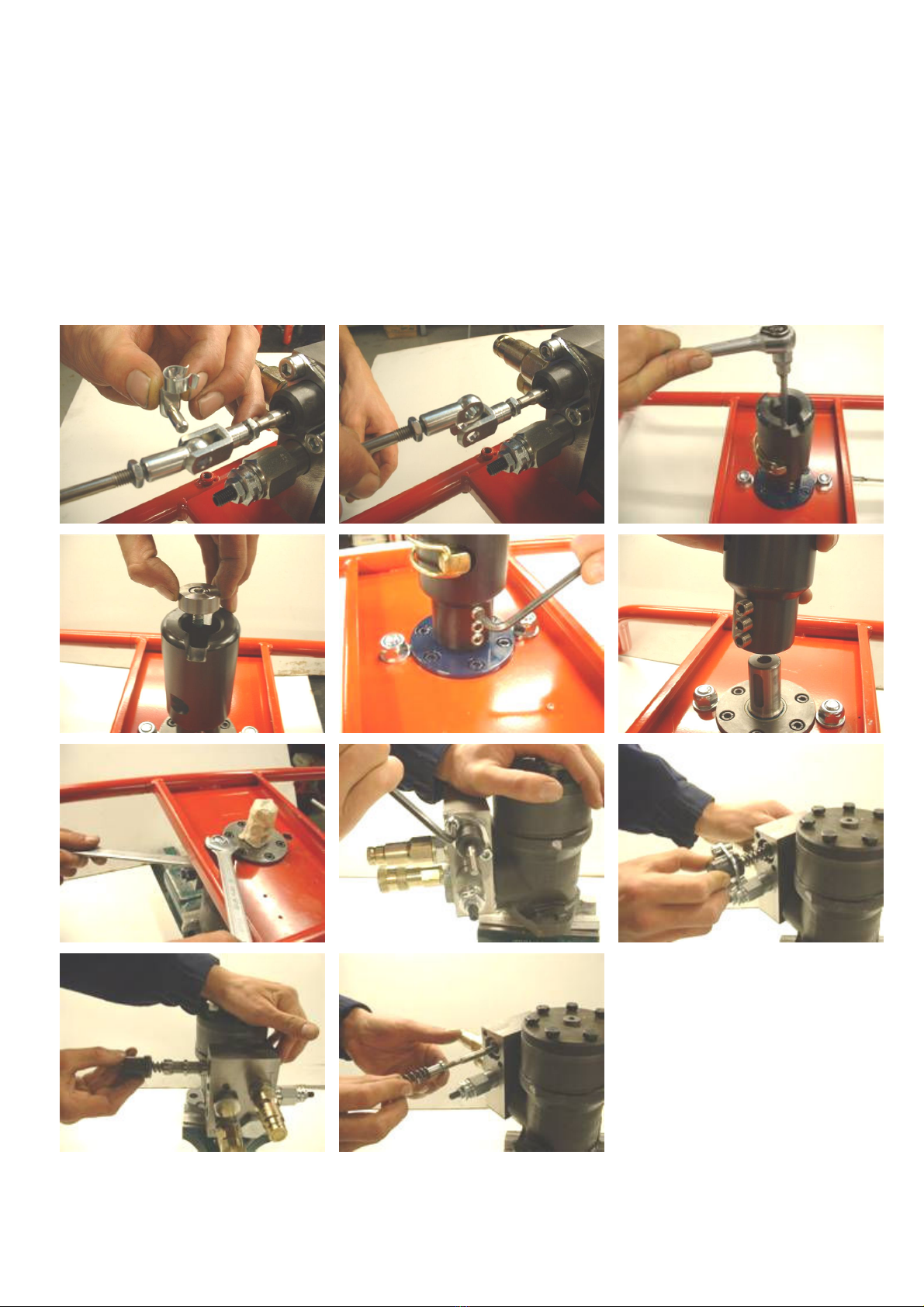
7. Dismounting of Main Components
Dismount the spring pin on the trigger rod. Dismount the screw at the bottom of the driving
shaft. Dismount the three screws at the side of the driving shaft. The driving shaft can now
be removed from the motor shaft. Dismount the two screws that fix the motor to the frame.
Remove the motor from the frame. Dismount the four screws that fix the trigger mechanism
to the valve block. Carefully pull out the trigger unit from the valve block.

9
Dismount the flat-face couplings from the fittings. Dismount the two fittings. Dismount the
pressure relief valve. Dismount the two banjo bolts that fix the valve block to the motor. The
valve block can now be removed from the motor.
Earth Drill Main Components
Table of contents
Other HYCON Drill manuals


