ICC VIP+ Air Insulated User manual

ICC - Model VIP+
Positive Pressure Chimney System
and Grease Duct
INSTALLATION AND MAINTENANCE INSTRUCTIONS
Scope and Recommendations
The ICC Model VIP+ is a double wall construction listed venting system designed for venting boilers, engines and other
commercial and industrial heating appliances. Positive pressure piping system up to 0" w.c. (15 Pa.).
Listed Models :
VIP+ Double Wall Air Insulated Chimney (1” Air Space)
VIP+ Double Wall 1" Fiber Insulation
VIP+ Double Wall 2" Fiber Insulation
VIP+ Double Wall 4" Fiber Insulation
Sizes:
Ø " (152mm) to Ø24" ( 10mm) Flue Diameters
G
WARNING
•
A major cause of vent related fires is failure to maintain required clearances (air space) to combustible materials. It is of utmost
importance that this venting system be installed only in accordance with these instructions. Do not fill the air space with insulating
material.
• Contact local building or fire officials about restrictions and installation inspection in your area.
Do not begin installing the ICC odel VIP+ venting system until you have carefully read the appliance and vent system installation instructions.
Use only ICC odel VIP+ components. Failure to do so will void the certification and warranty of the product.
Keep these installation and operating instructions in a safe location for future reference.
• Examine all components for possible shipping damage prior to installation.
• Proper joint assembly is essential for a safe installation.
• Follow these instructions exactly as written.
• Check tightness of joints upon completion of assembly.
• This venting system must be free to expand and contract.
• This venting system must be supported in accordance with these instructions.
• Check for unrestricted vent movement through walls, ceilings, and roof penetrations.
• Different anufacturers Have Different Joint Systems and Adhesives.
• Do Not ix Pipe, Fittings, or Joining ethods from Different anufacturers.
Tested and Listed to:
UL-103 , UL-2561 , ORD ULC C-959 , UL-1978 , ULC-S662
by Underwriters Laboratories, Inc (Listing # H16722)
ICC INDUSTRIAL CHIMNEY COMPANY INC.
400 J.F. Kennedy, St. Jérome
Québec, Canada, J7Y 4B7
Tel.: (450) 565-6336
Fax: (450) 565-6519
www.icc-rsf.com
VIP+_2016-04

Model VIP+ 2 Owner's Manual
Table of Contents
Scope and Recommendations ................................................................................................................................................ 1
Technical Specifications .......................................................................................................................................................... 3
Material ............................................................................................................................................................................... 3
Weight / Standard Thickness .............................................................................................................................................. 3
Venting Applications ........................................................................................................................................................... 3
B ilding Heating Appliance (BHA) Chimney (UL 103 Listing) : ...................................................................................... 3
1400°F Chimney (UL 2561 Listing) : .............................................................................................................................. 3
Positive Press re Listing (UL 103 and UL 2561) : ......................................................................................................... 3
540°C and 760°C Ind strial Chimneys (ULC C-959 Listing) : ........................................................................................ 3
S rro ndings / Enclos re ................................................................................................................................................... 3
Clearance to Comb stibles ................................................................................................................................................. 4
Part N mbers ...................................................................................................................................................................... 4
Chimney Sizing ................................................................................................................................................................... 5
Operation and Maintenance .................................................................................................................................................... 6
General Installation Notes .................................................................................................................................................. 6
Planning yo r Installation .................................................................................................................................................... 6
Tool checklist .................................................................................................................................................................. 6
R les of Safety ............................................................................................................................................................... 6
Chimney Joint Connection ...................................................................................................................................................... 7
S rface Preparation ............................................................................................................................................................ 7
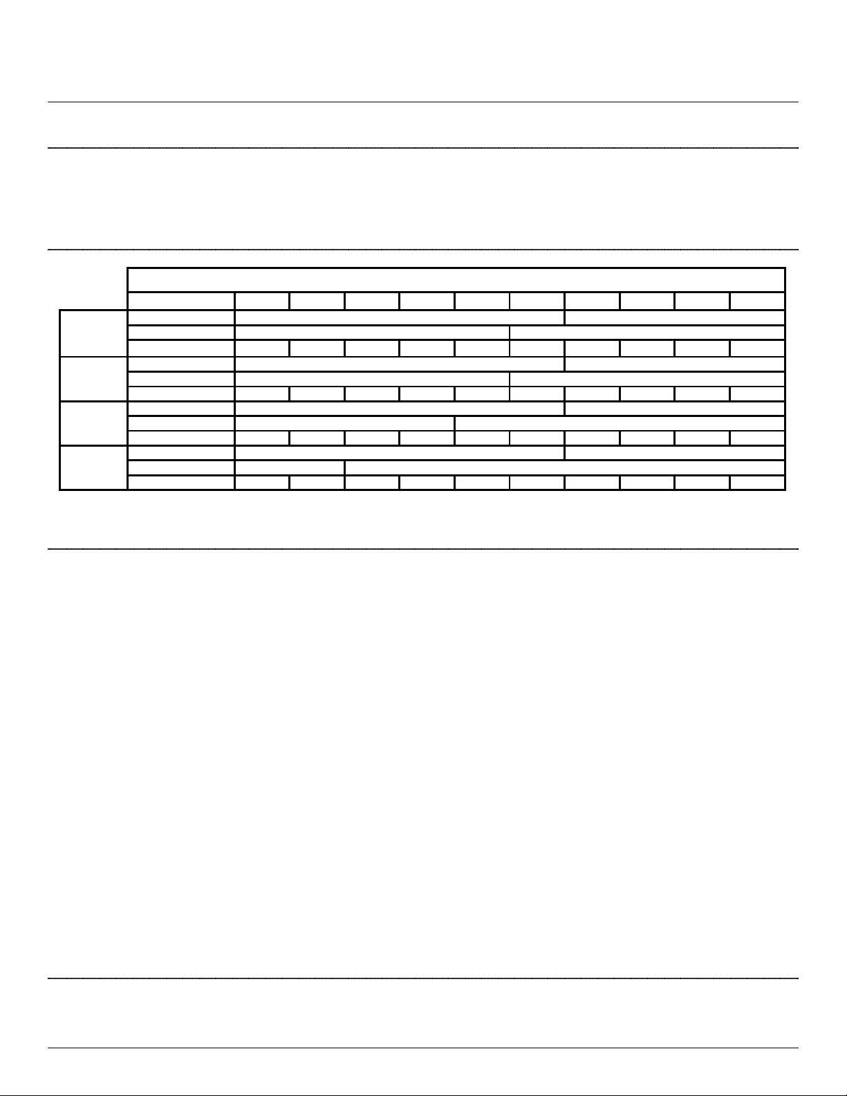
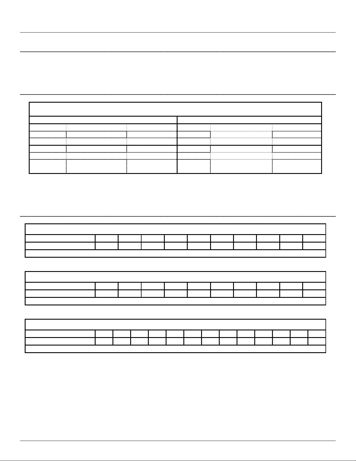
Sealant Application Chart ................................................................................................................................................... 7
Sealant Coverage ............................................................................................................................................................... 7
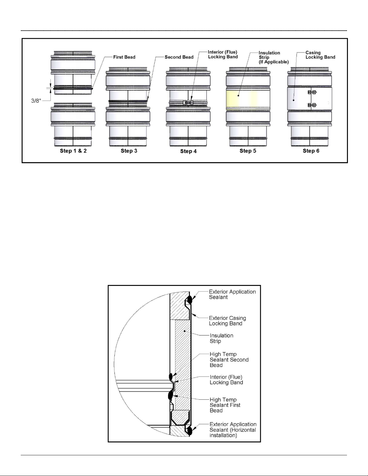
Joint Assembly – Low temperat re (600°F Max) Applications ........................................................................................... 8
Joint Assembly – High Temperat re (Above 600°F) Applications ...................................................................................... 9
Str ct ral S pports and G ides ............................................................................................................................................ 10
Base S pport .................................................................................................................................................................... 10
Wall S pport ..................................................................................................................................................................... 11
Wall G ide ........................................................................................................................................................................ 12
Floor G ide ....................................................................................................................................................................... 12
S pport Methods and System Design Limits .................................................................................................................... 13
Rigid Str ct ral Brace Specifications................................................................................................................................ 14
Elbows and Offsets ........................................................................................................................................................... 14
G y Wire ........................................................................................................................................................................... 15
Roof and Floor Penetrations ................................................................................................................................................. 16
Non-Comb stibles Floor Penetration................................................................................................................................ 16
Comb stible Floor Penetration – 1000°F Chimney (UL 103 & ULC C-959 Listings) ....................................................... 16
Comb stible Roof Penetration – 1000°F Chimney (UL 103 & ULC C-959 Listings) ........................................................ 17
Comb stible Roof Penetration – 1400°F Chimney (UL 2561 & ULC C-959 Listings) ...................................................... 18
Thermal Expansion ............................................................................................................................................................... 19
General Considerations .................................................................................................................................................... 19
Bellows Joint ..................................................................................................................................................................... 20
Expansion Length ............................................................................................................................................................. 21
Expansion Joints Installation ............................................................................................................................................ 22
Bellows Joint and Expansion Length in vertical r ns ................................................................................................... 22
Bellows Joint and Expansion Length in horizontal r ns ............................................................................................... 22
Adj stable Lengths ........................................................................................................................................................... 22
Grease D ct .......................................................................................................................................................................... 25
Listings and Applications .................................................................................................................................................. 25
Clearances and S rro ndings .......................................................................................................................................... 25
General Installation Instr ctions ....................................................................................................................................... 25
Fan Adapter ...................................................................................................................................................................... 26
Nozzle Length and Drains ................................................................................................................................................ 26
Cleano t and maintenance ............................................................................................................................................... 27
Access Door Section .................................................................................................................................................... 27
Wyes and Tees (Cleano t) ........................................................................................................................................... 28
Typical Grease D ct Installation ....................................................................................................................................... 29
WARRANTY .......................................................................................................................................................................... 30

Model VIP+ 3 Owner's Manual
Technical Specifications
Material
The odel VIP+ double wall vent is constructed of either stainless steel grade 304 or 316 for the flue and stainless steel grade 304 or 316 or
Galvalume for the casing. When required, the vent is insulated with high temperature mineral fiber insulation. Proper joint sealant or gasket material
is provided as per venting application (Low Temp or High Temp).
Weight / Standard Thickness
Table 1 - Standard Thickness and Chimney Weight
Ø
6
8
10
12
14
16
18
20
22
24
V P+
1” Air
Insulated
Flue Thickness
0.019" 0.025"
Casing Thickness
0.019" 0.025"
Weight (lbs / ft)
3.3 4.2 5.1 6.0 6.9 7.9 9.9 11.0 12.0 13.1
V P+
1” Fiber
Flue Thickness
0.019" 0.025"
Casing Thickness
0.019" 0.025"
Weight (lbs / ft)
4.4 5.6 6.9 8.1 9.3 10.6 13.0 14.4 15.7 17.1
V P+
2” Fiber
Flue Thickness
0.019" 0.025"
Casing Thickness
0.019" 0.025"
Weight (lbs / ft)
6.4 8.0 9.5 11.1 12.6 14.0 17.0 18.7 20.4 22.1
V P+
4” Fiber
Flue Thickness
0.019" 0.025"
Casing Thickness
0.019" 0.025"
Weight (lbs / ft)
11.3 13.5 15.7 18.0 20.2 22.4 26.0 28.3 30.2 33.5
On request, model VIP+ Venting System can be built using thicker gauge material. Contact Factory for eight specifications ith non-standard thickness
Venting Applications
Building Heating Appliance (BHA) Chimney (UL 103 Listing) :
Under this category, model VIP+ has been determined suitable for venting flue gases at temperatures not exceeding 538°C (1000°F) under
continuous operating conditions from gas, liquid, oil or solid fuel fired appliances. Also complies with operation (less than one hour) at temperatures
not exceeding 760°C (1400°F) and brief operation (maximum 10 minutes) at temperatures not exceeding 927°C (1700°F).
Building Heating Appliance Chimneys are suitable for use with Building Heating Appliances and Low Heat Appliances as described in the Chimney
Selection Chart of National Fire Protection Association (NFPA) Standard NO. 211.
1400°F Chimney (UL 561 Listing) :
Under this category, model VIP+ has been determined suitable for venting flue gases at temperatures not exceeding 760°C (1400°F) under
continuous operating conditions from gas, liquid, oil or solid fuel fired appliances. Also complies with brief operation (maximum 10 minutes)at
temperatures not exceeding 980°C (1800°F). As such, it is suitable for use with ovens and furnaces as described in the Chimney Selection Chart of
NFPA No. 211, in addition to other applications.
Positive Pressure Listing (UL 103 and UL 561) :
odel VIP+ has been determined suitable for use at a maximum of 60 inch water column internal pressure.
540°C and 760°C Industrial Chimneys (ULC C-959 Listing) :
Under this category, model VIP+ has been determined suitable for venting flue gases at temperatures not exceeding 760°C (1400°F) under
continuous operating conditions from gas, liquid or oil fired appliances. Also complies with brief operation (maximum 10 minutes) at temperatures not
exceeding 980°C (1800°F).
Surroundings / Enclosure
ICC odel VIP+ chimney is primarily intended to be used in fire resistive non-combustible surroundings or installed unenclosed. They are not
intended for use in one or two family residences.

Model VIP+ 4 Owner's Manual
CAUT ON
Do
not enclose this chimney in a chase or passageway of ordinary wood or other combustible material
Where the chimney extends through any zone of a building (outside that in which the heating appliance connected to it is located), it shall be
provided with an enclosure having a fire resistance rating equal to or greater than that of the floor, wall or roof assemblies through which it passes.
ICC odel VIP+ chimney may penetrate a combustible floor or roof using the appropriate parts and openings sizes. See section Roof and Floor
Penetrations for more details.
Where, according to local code, no chase enclosure is necessary, odel VIP+ chimney may be placed adjacent to walls of combustible construction
at the clearance specified on each chimney section and in the individual listing. (see Ta le 2 Clearances to Com usti les) Contact local building
or fire officials about restrictions and installation inspection requirements in your area.
Clearance to Combustibles
Ta le 2 - Clearances to Com usti les – Unenclosed Installation
Venting Application Maximum Flue
Temperature Flue Ø
VIP+ Chimney Model
Roof Kit
Configuration
VIP+
air
insulated
VIP
1" , 2" and 4" fi er
insulated
Building Heating Appliance
(BHA) Chimney 1000°F (538°C)
Ø6"
to 16"
6"
2"
*Insulated Firestop
Ø18" to 24"
10"
3"
1400F Chimney
1400°F (538°C)
Ø6" to 24"
6"
7"
*Ventilated Firestop
*See Roof and Floor Penetrations section for details
Part Numbers
The following section describes how part number are defined for most of the major VIP+ products. Please refer to other ICC documents like
pamphlets or price lists for a complete list standard of components part numbers. Contact ICC customer’s service for details.
Ta le 3A - Part Num ers Examples
Product
Type
1st diam
Ø
A
Part
Designation
Material
Insulation
Type
2nd diam
Ø
B
Description
Interior Exterior
type gauge
type gauge
JC
-
18
L4
A
24
A
24
0
n/a
18
" diameter x 4 foot
L
ength, Air
Insulated
,
304
stainless flue and casing
JE
-
8
E1
A
26
A
26
1
n/a
8
"
15° Elbow
,
1
" Fiber Insulated, 3
04
stainless flue and casing
JE
-
16
TR
B
26
C
24
4
n/a
16
"
90° Tee
,
4
" Fiber Insulated,
3
16
stainless flue and
Galvalume
casing
JM
-
6
SI
B
26
B
26
2
10
6" to
10" step increaser, 2" Fiber Insulated, 316 stainless flue and casing
JM
-
24
WS
A
24
A
24
1
n/a
24
"
Wall Support
,
1
" Fiber Insulated, 3
04
stainless flue and casing
…
…
The first section of the part number
regroups similar products under a
common product type designation.
Products are divided into the
following 5 categories :
Ta le 3B - Product Types
Product Types Designation
Product Type
Description
JC
Chimney
Length
JE
Elbows and Tees
JF
Flashings
J
iscellaneous
JS
Special Parts
This section identifies the
type of part within each of
the 5 products type. Here’s
Ta le 3C - Part Type Designation Examples
Product Type
Part
Type
Designation
Corresponding Part Description
JC
-
L1
1 foot Length
JC
-
L2
2 foot Length

Model VIP+ 5 Owner's Manual
a sample of some of the
more common part types :
JC
-
L3
3 foot Length
JC
-
L4
4 foot Length
JC
-
A1
Adjustable Length
12"
JC
-
A2
Adjustable Length
24"
JC
-
IT
Tapered
Increaser
JC
-
SI
Step Increaser
JC
-
LE
Expansion Length
JE
-
E1
15° Elbow
JE
-
E3
30° Elbow
JE
-
E4
45° Elbow
JE
-
E9
90° Elbow
JE
-
TR
90° Tee
JE
-
TY
45° Tee
JF
-
FF
Flat Flashing
JF
-
FA
Flashing 1/12
–
7/12
JF
-
FB
Flashing 8/12
–
12/12
J
-
WS
Wall Support
J
-
BS
Base Support
J
-
WB
Wall Band (or Wall Guide)
J
-
FG
Floor Guide
J
-
RC
Rain Cap
J
-
RS
Insulated Radiation Shield
J
-
VS
Ventilated Radiation Shield
J
-
EC
Exit Cone
J
-
FS
Firestop
J
-
TC
Tee Cap
J
-
TD
Drain Tee Cap
…
…
…
Ta le 3D - Material Designation
Material Designation
Material type
Comments
A
Stainless Steel 304
Available for flue and casing, 26 ga min (up to Ø16)
and 24 ga min (Ø18 and over)
B
Stainless Steel 316
Available for flue and casing, 26 ga min (up to Ø16) and 24 ga min (Ø18 and over)
C
Galvalume (Alu
-
Zinc)
Available for casing only, 26 ga min (up to Ø16) and 24 ga min (Ø18 and over)
* Standard materials only, for other options contact ICC customer’s service
Ta le 3E - Insulation Type Designation
Insulation Type Designation
Description
0
Double Wall Air
Insulated
Chimney (1” Air Space)
1
Double Wall 1" Fiber Insulation
2
Double Wall 2" Fiber Insulation
4
Double Wall 4" Fiber Insulation
Chimney Si ing
Complete chimney system sizing and capacity may be obtained from the “Chimney, Gas Vent, and Fireplace Systems” chapter of the ASHRAE
Handbook. You may also contact ICC Chimneys customer’s service for system sizing assistance. In spite of any sizing guidelines, when sizing ex-
haust systems, it is most important that the heating appliance, engine or turbine manufacturer’s installation instructions be followed. Not following
these instructions may result in inadequate chimney performance and/or a violation of the equipment manufacturer’s installation requirements.

Model VIP+ 6 Owner's Manual
Operation and Maintenance
KEEP YOUR VENT CLEAN. Your vent system should be examined annually by a qualified service company for the presence of soot or debris. Any
accumulation should be removed. Also, the vent system should be inspected periodically for the following:
1. Any leakage of condensate or combustion by-product at joints should be removed.
2. A defective drain trap loop should be repaired to prevent any leakage of exhaust gases inside the building area.
3. Any sign of corrosion.
General Installation Notes
1. odel VIP+ is to be installed in accordance with these installation instructions and with those of the appliance manufacturer.
2. Installation is to be in accordance with local building code requirements and National Codes.
3. Size the vent in accordance with the appliance manufacturer’s instructions. ICC will calculate correct vent sizing on request.
4. ake sure you read the appliance installation instructions for vent limitations such as maximum horizontal length, maximum number of elbows,
total vent height, common venting option, and other limitations that may affect the design and installation of this vent.
5. The maximum height of un-guyed vent above the roof is 6 feet.
6. The vent shall extend at least 3ft. above its point of penetration with the roof and at least 2 ft. higher than any wall, roof or adjacent building
within 10 ft of it.
7. DO NOT FILL THE AIR SPACE around the vent with insulation or any other material.
8. Do not allow sawdust or construction de ris to accumulate around the vent. Clean all areas surrounding the vent before closing up any
enclosed areas.
Planning your Installation
Prior to starting your installation, we suggest you take the following into consideration:
1. Check the appliance manufacturer's installation instructions to see all possible vent configurations.
2. Review all your options for the appliance location and also venting configuration. Try to minimize the alteration and reframing of structural
components of the building (wall studs, water pipes, electrical wiring, ceiling joists, roof rafters, etc.). It may be easier to change the location of
your appliance than to modify the building structure.
3. Use only Model VIP+ listed components. Do not use damaged parts.
4. Any penetrations of roof, ceilings, or floors must be properly fire-stopped as per venting applications described in these installation instructions.
5. Contact your local building authority and/or fire officials for permits, restrictions and installation inspections. You may also wish to contact your
building insurance representative.
Tool checklist
Tools and equipment you may need for your installation.
-
Eye protection
- Gloves
- Tape easure
- Extension cord
- arking pencil
- Nails
-
Stud sensor
- Square
- Circular saw
- Hand saw
- Drill
- Drill bits
-
Keyhole saw
- Ladder
- Level
- Pliers
- Caulking gun
- Proper application sealant
-
Hammer
- Screwdrivers
- Screws
- Plumb Bob
- Cold chisel
Rules of Safety
1. Wear gloves when handling metal parts with sharp edges.
2. Wear safety glasses.
3. Electrical tools must be grounded.
4. If a ladder, scaffold or a scissor lift platform is required, it must be in good condition, installed on a firm surface, and leveled.
5. When cutting a wall, floor or ceiling, be careful not to damage wiring, gas or water pipes. If these elements need to be relocated, work should be
done by a qualified person.

Model VIP+ 7 Owner's Manual
Chimney Joint Connection
Surface Preparation
All components have a male and a female end. The installation orientation is indicated on the labeling of each pipe section with an arrow. The arrow
indicates the direction of the exhaust gases. Clean all inner and outer surfaces of male and female ends with an appropriate organic solvent, such as
acetone or other commercial degreaser before applying a sealant.
Sealant Application Chart
Ta le 4 - Sealant Used as Per Venting Application (Must use approved factory supplied sealant)
600°F Max
Applications
1000°F Max
Applications
Indoors
Supplier
Max Temperature
Indoors
Supplier
Max Temperature
Inner Joints
X
-
TRASIL
HD
#4706
-
3
600°F (315°C)
Inner Joints
Fortafix Ceramix TC
2280°F (1250°C)
Outer Joints
n/a
n/a
Outer Joints
n/a
n/a
Outdoors
Supplier
Max Temperature
Outdoors
Supplier
Max
Temperature
Inner Joints
X
-
TRASIL
HD
#4706
-
3
600°F (315°C)
Inner Joints
Fortafix Ceramix TC
2280°F (1250°C)
Outer Joints
Any Silicone Sealant with
a min. rating of 400°F 400°F
Outer Joints
Any Silicone Sealant with
a min. rating of 400°F 400°F
Fortafix Ceramix TC cure time : Air dry for 24 hours and heated at 203°F (95°C) for 4 hours
X-Trasil HD #4706-3 cure time : Air dry for 24 hours
Sealant Coverage
Ta le 5A – Sealant coverage for Fortafix Ceramix TC High Temperature Ceramic Paste Sealant
Flue Ø (inches)
6"
8
"
10
"
12
"
14
"
16
"
18
"
20
"
22
"
24
"
Num er of joints per tu e
6.5
5
4
3.25
2.75
2.5
2.25
2
1.75
1.5
The coverage is about 21 linear feet per 11 oz cartridge
-
2 beads per joint (Ø 1/4") flue sealant
Ta le 5B – Sealant coverage for X-TRASIL HD #4706-3 High Temperature Silicone
Flue Ø (inches)
6"
8
"
10
"
12
"
14
"
16
"
18
"
20
"
22
"
24
"
Num er of joints per tu e
13
10
8
6.5
5.5
5
4.5
4
3.5
3
The coverage is about 42 linear feet per 11 oz cartridge
-
1 bead per joint (Ø 1/4") flue
sealant
Ta le 5C – Sealant coverage for Exterior Sealant ( ased on casing diameter)
Flue Ø (inches)
8
"
10
"
12
"
14
"
16
"
18
"
20
"
22
"
24
"
26
"
2
8
"
30
"
32
"
Num er of joints per tu e
26
20
16
13
11
10
9
8
7
6
26
20
16
The coverage is about 66 linear feet
per 11 oz cartridge
-
1 bead per joint (Ø 1/8") flue sealant

Model VIP+ 8 Owner's Manual
Joint Assembly – Low temperature (600°F Max) Applications
Figure 1
Step 1 : Apply one bead of X-TRASIL HD #4706-3 red silicone on the male end of the flue just under the formed bead.
Step 2 : Slip the top chimney male end into the expanded side of the lower chimney. Refer to chimney label for flue gases direction.
Step 3 : Assemble the flue locking band and secure by tightening the bolt . Do not remove the excess of sealant.
Step 4 : Install locking band insulation strip around the joint. (if applicable)
Step 5 : Install exterior casing locking band. Secure by tightening the 2 bolts.
Step 6 : Apply a bead of exterior sealant (see Ta le 4 and 5C) on the upper joint of the casing locking band (to prevent water infiltrations for outside
applications only)
Figure 2
Figure 3

Model VIP+ 9 Owner's Manual
Joint Assembly – High Temperature (Above 600°F) Applications
Figure 4
Step 1 : Apply one bead of Fortafix Ceramix TC on the male end of the flue approximately 3/8” under the formed bead.
Step 2 : Slip the top chimney male end into the expanded side of the lower chimney. Refer to chimney label for flue gases direction.
Step 3 : Apply a second Bead of Fortafix Ceramix TC just above the formed bead when chimneys are joined together (before interior locking band
assembly)
Step 4 : Assemble the interior locking band around the flue and secure by tightening the bolt . Do not remove the excess of sealant.
Step 5 : Install locking band insulation strip around the joint. (if applicable)
Step 6 : Install exterior casing locking band. Secure by tightening the 2 bolts.
Step 7 : Apply a bead of exterior sealant (see Ta le 4 and 5C) on the upper joint of the casing locking band (for outside applications only)
Figure 5

Model VIP+ 10 Owner's Manual
Structural Supports and Guides
Several supporting and guiding methods can be used to anchor a chimney for horizontal, vertical and offset displacement. These supports and
guides used with thermal expansion devices prevent bending stresses on the chimney elbows and joints. (see Thermal Expansion Section for
details) Supports and guiding methods are described in this Section.
Base Support
The Base Support is the most common
support. It can be used on any floor level
as a Vertical or Horizontal support. When
used to support the chimney in vertical
runs, it is attached to the floor by means
of anchors (by others, Ø 5/16” anchors or
bolts min. size). It can also be used to
support a horizontal run anchored
through wall or resting on a non-
combustible rigid structural brace (by
others, see Rigid Structural Braces
Specifications for details).
The Base Support assembly consists of a
9" chimney interior section (7" effective
length) that is welded to a steel plate.
The chimney section has female and
male ends forming just like any standard
length. It can be connected to any other
piece of piping with proper locking bands
and sealant. (see Chimney Joint
Connection Section for specific
instructions)
It is supplied with both an Interior Locking
Band a special External Finishing Band
(top female side) and an Insulation Strip.
(if applicable)
Installation :
1. Plate is secured to floor, wall or
structure with proper anchors. (See
Ta le 6 for aximum Supported
Chimney Height ( CH) per support and
Ta le 7 for aximum Horizontal Spacing
between Supports ( HS)).
2. Pipe sections are then attached to the
Base Support Interior Section in the
same manner as described in Chimney
Joint Connection Section depending on
the venting application.
3. Install insulation strips (when required)
and External Finishing Bands.
The Base Support is intended only for
attachment to NON COMBUSTIBLE
materials such as steel structure,
concrete or other types of masonry.
The Base Support is not suita le for
attachment to wood or com usti le
structures.
Figure 6
Figure 7
Figure 8

Model VIP+ 11 Owner's Manual
Wall Support
The Wall Support can be used on any
floor level as a Vertical or Horizontal
support. When used to support the
chimney in vertical runs, it is attached to
the wall by means of anchors (by others,
Ø 5/16” anchors or bolts min. size). It
can also be used to support a horizontal
run anchored on a ceiling or a non-
combustible rigid structural brace (by
others, see Rigid Structural Braces
Specifications for details).
The Wall Support assembly consists of a
9" chimney interior section (7" effective
length) that is welded to a steel plate
which is supported by angled brackets.
The chimney section has female and
male ends forming just like any standard
length. It can be connected to any other
piece of piping with proper locking bands
and sealant. (see Chimney Joint
Connection Section for specific
instructions)
It is supplied with both an Interior Locking
Band a special External Finishing Band
(top female side) and an Insulation Strip.
(if applicable)
Installation :
1. The angled brackets are secured to
wall, ceiling or structure with proper
anchors. (See Ta le 6 for aximum
Supported Chimney Height ( CH) per
support and Ta le 7 for aximum
Horizontal Spacing between Supports
( HS)).
2. Pipe sections are then attached and
sealed to the Wall Support Interior
Section in the same manner as described
in Chimney Joint Connection Section
depending on the venting application.
3. Install insulation strips (when required)
and External Finishing Bands.
The Wall Support is intended only for
attachment to NON COMBUSTIBLE
materials such as steel structure,
concrete or other types of masonry.
The Wall Support is not suita le for
attachment to wood or com usti le
structures.
Figure 9
Figure 10
Figure 11

Model VIP+ 12 Owner's Manual
Wall Guide
The Wall Guide is used as a lateral guide
to resist lateral load. It does not carry any
vertical chimney weight. It also maintains
the minimum clearance to combustibles.
(which can be adjusted from 2" to 6") It
can also be used to stabilize the chimney
horizontally.
The Wall Guide must be installed on the
chimney’s outer shell not on the outside
finishing band. The locking band must be
able to move without interfering with the
guide when thermal expansion occurs.
The Wall Guide collar is secured on the
outer casing of the chimney with the
collar’s 2 screws. The square angles must
be anchored to the wall (combustible walls
are allowed, at least 3x wood screws #10 x
2" per bracket) with a minimum of 3
anchors on each side. (by others)
See Ta le 7 for aximum Vertical Spacing
between 2 Supports or Guides (MVS)
Figure 12
Figure 13
Floor Guide
The Floor Guide is mainly used as a
chimney stabilization device at floor
penetrations. It does not carry any vertical
chimney weight. It also maintains the
minimum clearance to combustibles.
The Floor Guide must be installed on the
chimney’s outer shell not on the outside
finishing band. The locking band must be
able to move without interfering with the
guide when thermal expansion occurs.
The Floor Guide collar is secured on the
outer casing of the chimney with the
collar’s 2 screws. The 4 square brackets
must be anchored to the floor (combustible
floors are allowed, at least 4x wood screws
#10 x 2" per bracket) with a minimum of 4
anchors per bracket. (by others)
See Ta le 7 for aximum Vertical Spacing
between 2 Supports or Guides (MVS)
Figure 14
Figure 15

Model VIP+ 13 Owner's Manual
Support Methods and System Design Limits
The supporting and guiding design parameters presented in this section must be closely followed to insure that your venting system is properly
designed. Chimney must be supported (with base or wall support) at least every (MCH) feet and guided at least every (MVS) feet. A horizontal run
must be supported (with a base or wall support) at least every (MHS) feet. See Figure 16 for typical System Design Limits application.
Ta le 6 - Maximum Supported Chimney Height and Support Method (MCH)
Support Method Ø VIP+ Chimney Model –
MCH
(feet)
VIP
+
AIR Insulated
VIP+
1" Fiber
VIP
+
2" Fiber
VIP+
4" Fiber
Base Support
Ø 6" to 24"
51'
39'
30'
20'
Wall Support
Ø 6" to 24"
38'
29'
23'
15'
Ta le 7 - Maximum Horizontal and Vertical Spacing (MHS and MVS)
Ø Dimensions
VIP+
Model
–
Dimension
(feet)
VIP+
Air
Insulated
VIP+
1" Fiber
VIP+
2" Fiber
VIP+
4" Fiber
6" to 16"
MHS
: aximum Horizontal Spacing between Supports 16' 14' 12' 8'
MVS
: aximum Vertical Spacing between 2 Supports or Guides 13' 13' 12' 10'
18" to 24"
MHS
: aximum Horizontal Spacing between Supports 12' 10' 8' 6'
MVS
: aximum Vertical Spacing between 2 Supports or Guides 10' 10' 9' 8'
Figure 16

Model VIP+ 14 Owner's Manual
Rigid Structural Brace Specifications
When necessary a Support Assembly must be secured to the building with a rigid structural framework. Satisfactory performance and service life of
VIP+ Chimney Systems requires the product be rigidly braced and supported. Every installation presents unique support and bracing requirements
and the following guidelines will provide minimum acceptable sizes for the mechanical hardware supplied by others.
Figure 17
Figure 18
Elbows and Offsets
• Elbows are used for changes in direction in horizontal or vertical portions of a chimney system.
• Elbows are used in combination to make up different angles in horizontal and vertical breechings of the chimney.
• Special care should be exercised in designing the bracing for elbows because elbows can only take limited forces due to any bending
moments
• Except where absolutely necessary, sloped or horizontal offsets in the vertical portion of a chimney above the breeching should be
avoided.
• Sloped offsets require more expansion joints and secure bracing above and below elbows.
• Structural parts such as posts or beams may also be needed to hold chimney supports in position.
• There is no limit on the angle or slope of an offset for gas or liquid fuel burning appliances
• Chimneys for combination fuel heating appliances that are capable of burning solid fuel or are convertible to solid fuel are limited to 30º
slope even if the current choice of fuel is gas or oil.
• The maximum length of offset, if one is necessary, is determined by strength considerations. The maximum dimension between supports
(Base Supports or Wall Supports), given as the “MHS” dimension in the Support Methods and System Design Limits (Ta le 7) section
of these instructions, is applicable to all horizontal and sloped orientations. (See Figure 20)
• To assure proper guidance of expansion joints and to prevent unnecessary joint bending, use an adequate number of supports at closer
intervals.
• With generator set or turbine exhaust use Bellows Expansion Joint below each support in offset runs. For boiler exhaust use an Expansion
Length.
• The ends of any sloped or horizontal offset must be anchored to prevent overstressing elbows and to assure proper operation of expansion
joints.
• With frequent re-support, there is no structural or operational limit to the length of horizontal or sloped portions of a VIP+ Chimney,
providing the system meets the capacity, pressure drop or available draft requirements of the appliance or equipment.
• The carrying capacity of the VIP+ supports and their structure attachments must consider the weight of the offset plus whatever vertical
pipe is carried by that support. See Ta le 6 for height limit of VIP+ supports (MCH).

Model VIP+ 15 Owner's Manual
Figure 19
Figure 20
Guy Wire
The Guy Wire
s
Sections
are
used where the chimney extends more than 6'
above the roof. For roof installations where freestanding height limits are
exceeded, Rigid Roof Braces and Cable Bracings are required to resist
heavy wind conditions and prevent structural damage. Each Guy Wire will
allow height extension by a maximum value of 1x MVS (see Ta le 7). The
Guy Wire Band is made to hook-up 3 guy wire (by others) at 120° apart or to
be secured with Rigid Roof Brace (by-others). The cables are secured to
the roof by mean of tensioners (by-others) and anchors (by others).
Expansion joints may be required in order to minimize the effects of thermal
expansion. The chimney has to be secured below the roof line with a
support to maintain structural integrity as described in the Support Methods
and System Design Limits Section. Use cables, roof anchors, braces and
tensioners designed for 30 lb. per sq. ft. force on chimney projected area.
Figure 21
Figure 22
Guy Wire Section

Model VIP+ 16 Owner's Manual
Roof and Floor Penetrations
Non-Combustibles Floor Penetration
inimum openings when passing through a floor made of
non-combustible materials such as steel structure, concrete
block or other type of masonry must be at least 2" larger than
the outside diameter of the chimney leaving an unobstructed
gap of 1” all around the chimney. (OD + 2")
It is also required to use a Firestop combined with a Floor
Guide or a Base Support in order to maintain clearance and
stability. Expansion joints may be required in order to
minimize the effects of thermal expansion.
Figure 23
Combustible Floor Penetration – 1000°F Chimney (UL 103 & ULC C-959 Listings)
* The instructions in this section are valid for Building Heating Appliances (BHA) with venting flue gases at temperatures not exceeding 538°C
(1000°F) under continuous operating conditions from gas, liquid, oil or solid fuel fired appliances. Also complies with operation (less than one hour)
at temperatures not exceeding 760°C (1400°F) and brief operation (maximum 10 minutes) at temperatures not exceeding 906°C (1700°F).
A
n
Insulated
Radiation Shield must be used where a chimney passes through a
floor made of combustible materials. The Radiation Shield assembly is primarily
used for floor and roof penetration (see following section for roof penetration) to
protect combustible materials from heat radiated from the chimney, maintain
clearance and provide firestoping. See Ta le 8 for minimum square framing
dimensions.
1. The Radiation Shield is inserted into the framing hole from under the floor and
secured from under the Firestop Plate using 8 wood screws #10 x 2".
2. The Radiation Shield height can be adjusted to the floor thickness by sliding
the adjustable sleeve. Excess insulation must be trimmed.
3. For minimum height adjustment remove the adjustable sleeve and trim
insulation. The shield must be at least as tall as the floor thickness and cover all
combustible material exposed in the floor opening.
4. Can be pared with a floor guide (above the floor) for better stability.
Figure 24
Figure 25
Figure 26

Model VIP+ 17 Owner's Manual
Ta le 8 - Minimum Square Framing Dimensions for Com usti le Materials (Insulated and Ventilated Radiation Shields)
Ø
6
8
10
12
14
16
18
20
22
24
VIP+
air insulated and
1" fi er (OD = ID + 2")
14" 16" 18" 20" 22" 24" 26" 28" 30" 32"
VIP+
2" fi er
(OD = ID + 4")
16" 18" 20" 22" 24" 26" 28" 30" 32" 34"
VIP+
4" fi er
(OD = ID + 8")
20" 22" 24" 26" 28" 30" 32" 34" 36" 38"
Combustible Roof Penetration – 1000°F Chimney (UL 103 & ULC C-959 Listings)
* The instructions in this section are valid for appliances with venting flue gases at temperatures not exceeding 538°C (1000°F) under continuous
operating conditions from gas, liquid, oil or solid fuel fired appliances. Also complies with operation (less than one hour) at temperatures not
exceeding 760°C (1400°F) and brief operation (maximum 10 minutes) at temperatures not exceeding 906°C (1700°F).
The Flat Roof Penetration requires the use of an Insulated Radiation Shield, a Floor Guide and a Flashing Kit. The Flat Roof Penetration
assembly instructions are primarily used for Boiler Applications where a chimney section passes through a roof made of combustible material. It is
designed to be installed on a flat roof (or roof curb) 8"to 16" high. The roof framing dimensions are presented in Ta le-8 in the previous Section.
1. The Radiation Shield is inserted into the framing hole from under the roof and secured from under the Firestop Plate with 8 wood screws #10 x 2".
2. The Radiation Shield height can be adjusted to the roof curb thickness by sliding the adjustable sleeve. Excess insulation must be trimmed.
3. For minimum height adjustment remove the adjustable sleeve and trim insulation. The shield must be at least as tall as the floor thickness and
cover all combustible material exposed in the floor opening.
4. The Floor Guide is secured to the top roof (or roof curb) using 4 wood screws #10 x 2" wood screws per bracket.
5. The Flat Flashing is then lowered above the Floor Guide and the Storm Collar secured to the chimney section with the screws supplied.
* A Ventilated Roof Penetration option is also available where air circulation between the chimney and the roof structure is wanted. The Ventilated
Flashing option may serve as a ventilation outlet in small boiler rooms with gravity air supply. (See Com usti le Roof Penetration - Engines
(1400°F) Section)
Flat Roof
Figure 27
Roof Curb
Figure 28

Model VIP+ 18 Owner's Manual
Combustible Roof Penetration – 1400°F Chimney (UL 2561 & ULC C-959 Listings)
* The instructions in this section are valid for appliances with venting flue gases at temperatures not exceeding 760°C (1400°F) under continuous
operating conditions from gas, liquid, oil or solid fuel fired appliances. Also complies with brief operation (maximum 10 minutes) at temperatures not
exceeding 906°C (1700°F).
The Flat Roof Penetration requires the use of a Ventilated Radiation Shield, a Floor Guide and a Flashing Kit. The Flat Roof Penetration
assembly instructions are primarily used for Engines or High Temperature Applications where a chimney section passes through a roof made of
combustible material. It is designed to be installed on a flat roof (or roof curb) 4" to 15" high. The Radiation shield sleeve must extend under the roof
by a minimum of 3”. The roof framing dimensions are presented in Ta le 8 in the previous Section.
1. The Radiation Shield is inserted into the framing hole from above the roof and secured with screws on the roof top or roof curb.
2. The Floor Guide is secured to the top roof (or roof curb) using 4 wood screws #10 x 2" wood screws per bracket.
3. The Flat Flashing is then lowered above the Floor Guide and the Storm Collar secured to the chimney section with the screws supplied.
Flat Roof
Figure 29
Roof Curb
Figure 30

Model VIP+ 19 Owner's Manual
Thermal Expansion
General Considerations
1. When odel VIP+ is in use, thermal expansion will occur on the inner flue and outer casing.
2. A good estimation for thermal expansion is approximately 1" per 100' chimney length per 100°F of temperature rise between the flue
gases and the surroundings temperatures.
Thermal Expansion (inch) = ( Length (feet) / 100 ) x ( ∆T (°F) / 100 )
3. Whether in the vertical or the horizontal run, the thermal expansion of the inner pipe depends on the inner flue temperature and the length
of the chimney between two fixed points.
4. Good installation requires that expansion greater that 1/4” must be compensated with either a Bellow Joint or an Expansion Length. The
selection of the expansion joint device depends on the system pressure* :
*For engine or turbine exhaust system requiring pressures up to 60 inches of water column, or where the construction must be absolutely
gas tight, all Bellows Joints are recommended for expansion and vibration movements of the exhaust.
*Low pressure systems, such as boilers (up to 6 inches water column), can effectively use the Expansion Length.
Table 9 - Allowable lengths for 1/4” thermal expansion
∆
T
(
Gas
T
–
Surr
oundings
T)
(
°
F)
Length
between fixed points
200
12'6"
300
8'4"
400
6'3"
500
5'0"
600
4'2"
700
3'7"
800
3'1"
900
2'9"
1000
2'6"
5. Tees and Elbows are not designed to resist bending moment forces as a result of thermal expansion. The forces due to thermal expansion
therefore need to be compensated by expansion joints.
6. Expansion joints are not designed to withstand lateral forces so they must be properly supported and guided.
7. Because the amount of outer casing movement is the same as the inner flue, the outer casing must slide to avoid excessive forces on
tees, elbows or fixed points. To accommodate outer casing movements, wall guide, floor guide and suspension bands must allow
movement of the chimney.
8. When re-supporting a system with considerable height and thermal expansion, Expansion Lengths or Bellow Joints must be used just
below every fixed support above the first to compensate for thermal expansion.
9. Spacing of Guides and Supports, when a thermal expansion part is used, should not be greater than that specified in ta le-6 and -7.
10. Proper guiding and support of expansion parts often requires closer spacing.

Model VIP+ 20 Owner's Manual
Bellows Joint
1. For exhaust pressure up to 60 inches of water column, it will
compensate for up to 3" max of expansion. See Ta le 10 for
maximum run with one bellow.
2. Bellow Joints comes with a liner to protect the bellow and to have a
smooth flow.
3. Installation is done the same way as described in the Chimney Joint
Connection Section.
4. Bellow Joint is used for axial movements and vibration only and must
be accurately supported and guided. This part has limited lateral
movement. Lateral offsets and parallel misalignments should be
avoided.
5. The lined bellows requires careful positioning of piping guides to avoid
interference on thermal expansion.
Figure 31
Table 10 - Maximum Run with One ellows Joint (3" expansion)
Operating temp. [°F]
Max distance
for one ellow joint [feet]
700
42.8
800
37.5
900
33.3
1000
30.0
1100
27.3
1200
25.0
1300
23.1
1400
21.4
This manual suits for next models
3
Table of contents
Popular Fan manuals by other brands

Ebmpapst
Ebmpapst A4D630-AJ01-02 operating instructions

Greenheck
Greenheck SP110 Installation, operation and maintanance manual

Emerson
Emerson LK53 owner's manual

Adaptive Sound
Adaptive Sound 'LectroFan owner's guide

Monte Carlo Fan Company
Monte Carlo Fan Company 4vG42XXd-L series installation instructions

Hunter
Hunter Exeter installation manual