4BaxallICESeriesFixedDomeCameras
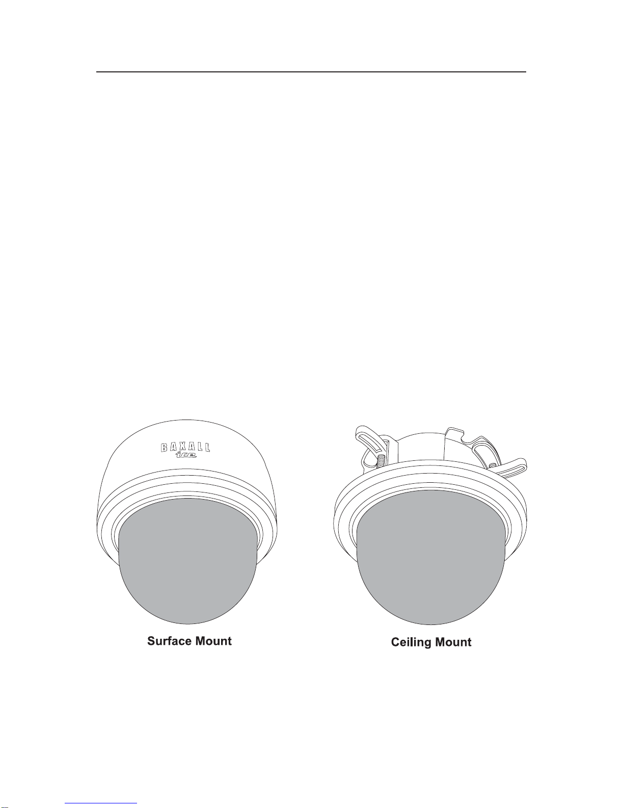
SURFACE MOUNT INSTALLATION
1. Toremovethedomecover,rotateitcounter-clockwiseandgentlypullitawayfromthecamerabody(figure
1). The inner liner can now be removed.
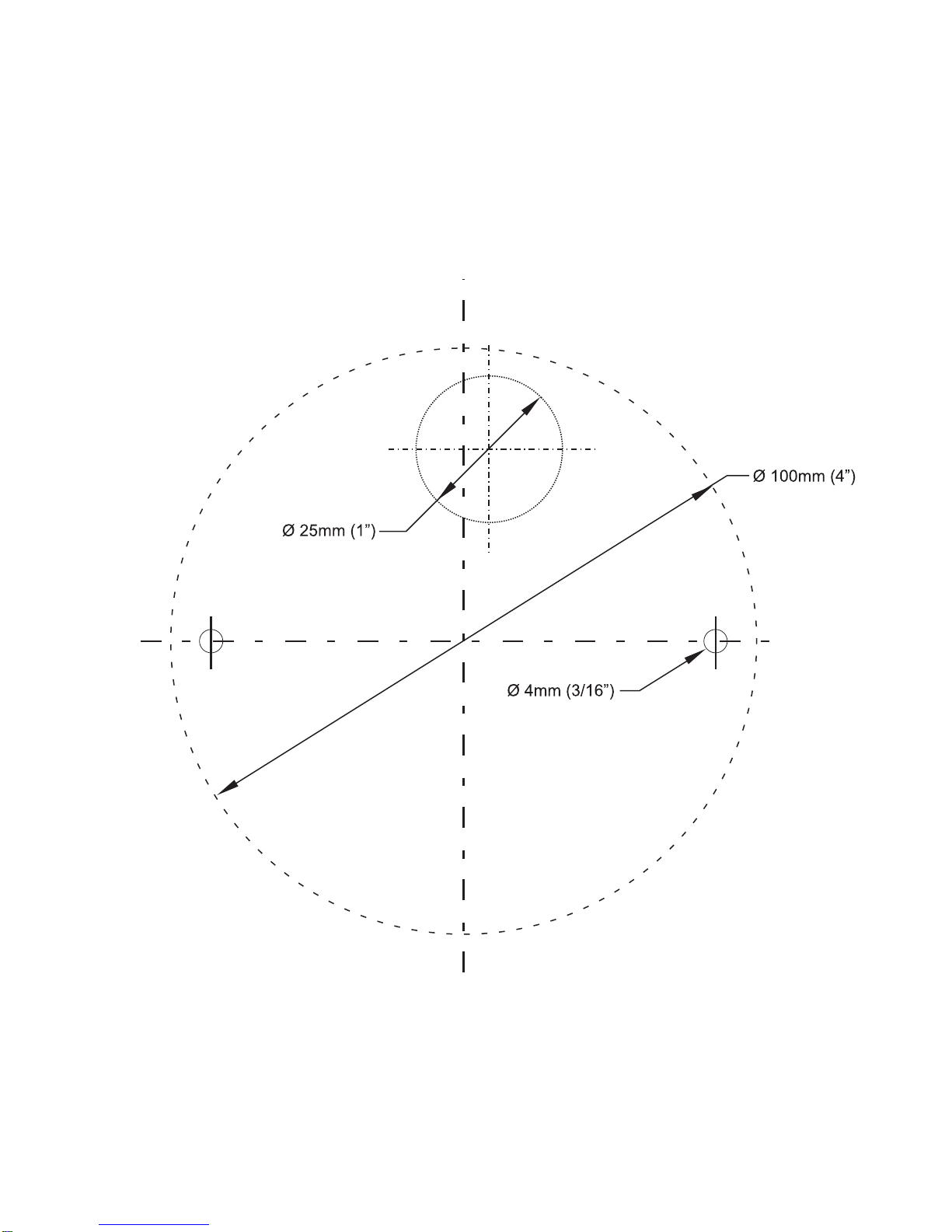
2. Using the template supplied at the rear of this manual, mark and drill the holes required for fixing.
Using the two 80 mm mounting screws (2, figure 2), attach the dome camera to the surface as shown. Do
not over tighten the fixing screws. The screws can be used on their own if the surface is of a suitable
material(e.g.wood),butplasticanchors(1,figure2)mustbeusedwherethesurfaceisofbrickormasonry
construction.
Run the power and video cables to the camera. Cables may be fed through the ceiling (3, figure 2) or
throughthecutoutinthesideofthecamera shroud(4,figure2).Remove the cutoutwithasharpknifeand
use a round file to smooth the edges if necessary.
3. Connect the video to either the BNC at the end of the flying lead (1, figure 6) or directly to the BNC
(2, figure 6). Use only one of the BNC connectors to connect video.
NOTE: ICED-B3H39 only - pass the video lead through the supplied ferrite (4, figure 6) as shown.
Connect the power to the power terminals (3, figure 6). These cameras are designed to operate from a
12VDCor 24VACpowersupply. Connectionsandpolarity are indicatednextto the terminals.The power
supply must be of UL Listed, Class 2 isolated type.
RECESS MOUNT INSTALLATION
1. To recess mount the camera, the shroud must be removed. Gently squeeze together opposite sides of
the shroud as shown and lift it away from the camera body (figure 3).
2. Using the template supplied at the rear of this manual, mark and cut a 4” (100 mm) diameter hole.A
suitably sized hole saw can also be used.
To prepare for installation use a suitable screwdriver to loosen the three fixing clamps sufficiently to
accommodate the thickness of the tile or ceiling (figure 4).
3. Connect the video to either the BNC at the end of the flying lead (1, figure 6) or directly to the BNC
(2, figure 6). Use only one of the BNC connectors to connect video.
NOTE: ICED-B3H39 only - pass the video lead through the supplied ferrite (4, figure 6) as shown.
Connect the power to the power terminals (3, figure 6). These cameras are designed to operate from a
12VDCor 24VACpowersupply. Connectionsandpolarity are indicatednextto the terminals.The power
supply must be of UL Listed, Class 2 isolated type.
4. Insert the camera into the hole. Using a suitable screwdriver, tighten the three fixing clamps as shown
(figure 5). Do not overtighten the clamps.