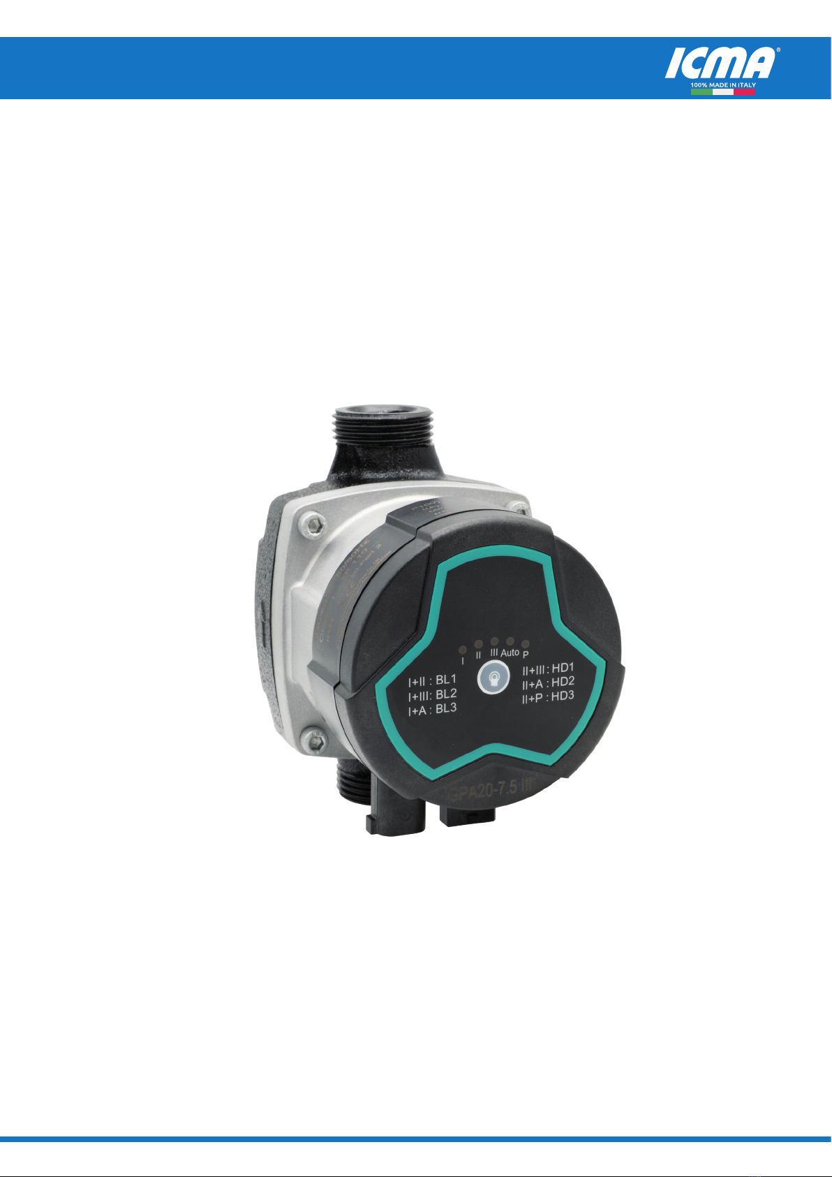
ELECTRONIC CIRCULATOR FOR SOLAR THERMAL SYSTEMS - Art. S167
FI.S167.EN.C - 03/2023
Icma
SpA
-
Via
Garavaglia,
4
-
20012
C
uggiono
(MI)
IT
AL
Y
T
el:
+39
02
97249134
-
+39
02
97249135
-
w
ww.icmaspa.it
-
[email protected]2
INDEX
IMPORTANT SAFETY AND INSTALLATION INSTRUCTIONS...................................................................................................3
1. SYMBOL DESCRITPION.............................................................................................................................................................4
2. OVERVIEW....................................................................................................................................................................................4
2.1 Advantages of installation of the pump..........................................................................................................................4
3. SERVICE CONDITIONS...............................................................................................................................................................5
3.1 Ambient Temperature............................................................................................................................................................5
3.2 Relative humidity (RH)..........................................................................................................................................................5
3.3 Media (conveying liquid) temperature...............................................................................................................................5
3.4 System Pressure......................................................................................................................................................................5
3.5 Protection Level......................................................................................................................................................................5
3.6 Inlet Pressure...........................................................................................................................................................................5
3.7 Pumping Liquid........................................................................................................................................................................5
4. INSTALLATION.............................................................................................................................................................................6
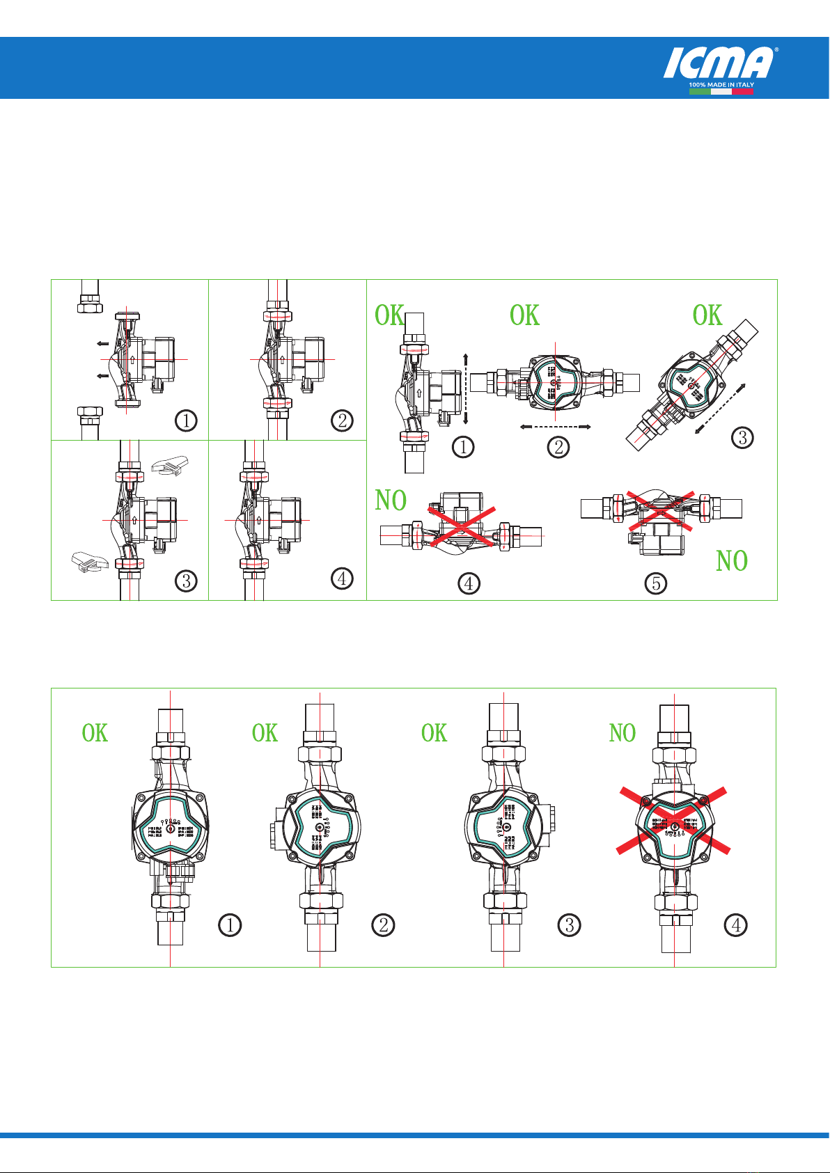
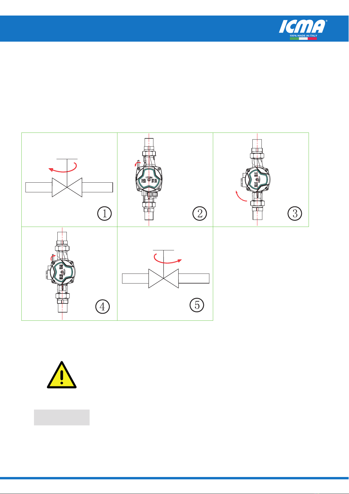
4.1 Position of Junction Box.......................................................................................................................................................6
4.2 Thermal insulation of the pump body...............................................................................................................................8
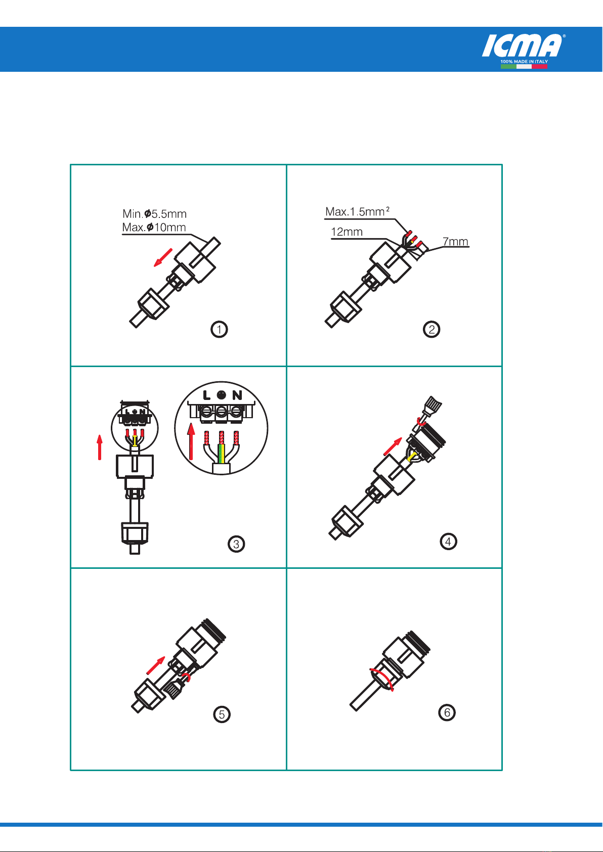
5. ELECTRICAL CONNECTION......................................................................................................................................................9
6. CONTROLS ON CONTROL PANEL..........................................................................................................................................11
6.1 Fault code display status....................................................................................................................................................11
6.2 Light area displaying the settings of the pump.............................................................................................................12
6.3Buttonforselectingthepumpsettings............................................................................................................................12
7. SETTING OF THE PUMP...........................................................................................................................................................12
7.1 The control on the pump..................................................................................................................................................13
8. PWM SIGNAL CONTROL MODE............................................................................................................................................14
8.1 Control and Signal................................................................................................................................................................14
8.2 Interface..................................................................................................................................................................................14
8.3 PWM Input Signal..................................................................................................................................................................15
8.4 PWM Feedback Signal.........................................................................................................................................................16
8.5 How to use the signals........................................................................................................................................................16
9. USE OF BYPASS VALVE............................................................................................................................................................17
9.1 Manually-operated bypass valve.......................................................................................................................................18
9.2 Automatic bypass valve (temperature control type).................................................................................................18
10. START UP.....................................................................................................................................................................................18
10.1 Before Start Up...................................................................................................................................................................18
10.2 Exhaust the Motor Pump.................................................................................................................................................18
10.3 Gas-exhausting of heating system.................................................................................................................................18
11. SETTINGS AND PERFORMANCE OF PUMP.......................................................................................................................19
11.1 Relationship between pump settings and its performance...................................................................................19
12. PERFORMANCE CURVE...........................................................................................................................................................20
12.1 Performance curve guide.................................................................................................................................................20
12.2 Curve conditions.................................................................................................................................................................20
12.3 Performance Curve............................................................................................................................................................20
13. CHARACTERISTICS...................................................................................................................................................................21
13.1 Description of nameplate................................................................................................................................................21
13.2 Model explanation.............................................................................................................................................................22
14. TECHNICAL PARAMETERS AND INSTALLATION DIMENSIONS...................................................................................23
14.1 Technical data......................................................................................................................................................................23
14.2 Installation Dimensions....................................................................................................................................................24
15. FAULT CHECKLIST.....................................................................................................................................................................25