ADS-AR-FOR02 maestro.idatalink.com
FORD EDGE 2011-2017
Automotive Data Solutions Inc. © 2017 4
INSTALLATION INSTRUCTIONS
BEFORE INSTALLING
• Update the aftermarket amplifier with special firmware
to make it compatible with Maestro RR.
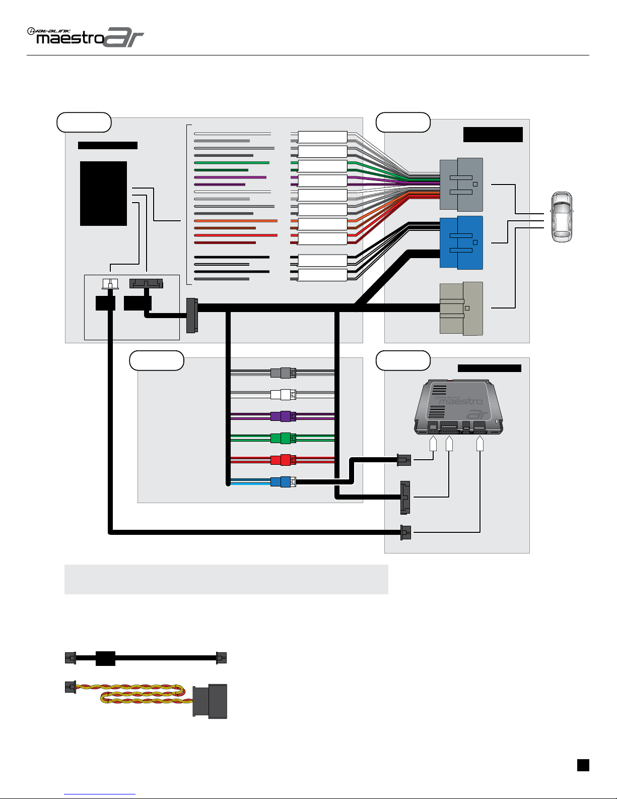
STEP 1
• Remove the factory amplifier (refer to wire chart for
amplifier location).
• Configure the 2 pin connectors on the AR-FO2 T-harness
as shown on the wiring diagram.
STEP 2
• Connect the factory amplifier harnesses to the AR-FO2
T-harness.
STEP 3
• Connect the wires from the AR-FO2 T-harness to the
aftermarket amplifier.
Note 1:
If you are running your own speaker wires from the
amplifier to the speakers, this step is not necessary.
Note 2:
The amplifier output colors and labels on the FO2 T-harness
do not correspond to the vehicle. For vehicle specific wiring
designation, see the wiring chart.
• Plug the connector from the AR-FO2 T-Harness into the
female adapter (supplied by Audison). Plus the adapter into
the aftermarket amplifier.
• Plug the Data cable (supplied by Audison) to the data port
of the aftermarket amplifier.
STEP 4
• Connect all the harnesses to the Maestro AR module.
Note 3:
The aftermarket amplifier will not turn OFF with the key, it
will shut down when the vehicle goes to sleep.
Note 4:
The optical input source will be disabled when connected
to Maestro AR for Prima amplifiers that have hardware
revision R2 or lower.
The optical input of the Prima Amplifier will be used for
audio when the OEM radio source “AVINPUT” is used. The
volume knob will change the optical volume in the Prima
amplifier in vR3 or higher.
• For technical assistance call 1-866-427-2999 or e-mail
com/support” and “www.12voltdata.com/forum/”
1