IDS GeoRadar Hydra Series User manual

MNG/2017/009
Rev 1.1
HYDRA
User manual

INDEX
IDS Ingegneria dei Sistemi S.p.A. MNG/2017/009 Rev 1.1 2/ 54
INDEX
1 INTRODUCTION.....................................................................4
1.1 Purpose.................................................................................4
1.2 Application field....................................................................4
1.3 Authorization for use –national restriction .........................4
2 ABOUT THE MANUAL............................................................5
2.1 Manual layout.......................................................................5
2.2 Symbols.................................................................................5
2.3 Glossary and acronyms.........................................................5
2.3.1 Acronyms ..............................................................5
2.4 Reference..............................................................................5
3 SAFETY DIRECTIONS..............................................................6
3.1 Description............................................................................6
3.2 Definition of Use...................................................................6
3.3 Reasonably Foreseeable Misuse...........................................6
3.4 Limits of Use..........................................................................6
3.5 Responsibilities .....................................................................6
3.6 Hazards of Use......................................................................7
4 GENERAL DESCRIPTION.......................................................12
4.1 System Configurations........................................................12
4.2 System Features..................................................................13
4.3 System Composition ...........................................................14
5 SYSTEM BREAKDOWN.........................................................15
5.1 HYDRA Radar Sensor...........................................................15
5.2 Antennas.............................................................................17
5.3 Positioning Unit...................................................................18
5.4 Tripod..................................................................................21
5.5 Power Supply Unit...............................................................22
5.6 Tablet ..................................................................................24
5.7 Camera................................................................................25
5.8 Laser....................................................................................26
5.9 Cables..................................................................................27
5.10 Siren Alarm..........................................................................31
5.11 Spotlight..............................................................................32
6 HOW TO INSTALL AN HYDRA-U SYSTEM.............................33
6.1 Preliminary operations........................................................33
6.1.1 Choose the Installation Site ......................................................... 33
6.2 HYDRA installation ..............................................................35
7 DISMANTLING AN HYDRA SYSTEM .....................................42
7.1 Dismantling the measurement site.....................................42
8 MAINTENANCE AND TROUBLESHOOTING..........................43
8.1 Maintenance.......................................................................43
8.2 Troubleshooting..................................................................43
9 IDS GEORADAR ON-LINE ASSISTANCE.................................44
9.1 Download Area ...................................................................44
9.2 Screen Connect Support Center Remote Assistance..........44

INDEX
IDS Ingegneria dei Sistemi S.p.A. MNG/2017/009 Rev 1.1 3/ 54
9.2.1 HOW TO USE THE SCREEN CONNECT SERVICE ...............44
10 APPENDIX A –SYSTEM PACKAGING....................................46
APPENDIX B - TECHNICAL SPECIFICATIONS OF HYDRA.................................48
APPENDIX C - DISCLAIMER............................................................................49
APPENDIX D –WARRANTY CONDITIONS......................................................51
APPENDIX E - RADIO-FREQUENCY EXPOSURE COMPLIANCE .......................53
APPENDIX F - CONTACTS ..............................................................................54
INTRODUCTION
IDS Ingegneria dei Sistemi S.p.A. MNG/2017/009 Rev 1.1 4/ 54
1INTRODUCTION
This document describes the HYDRA system (Hyper Definition Radar), and
particularly refers to the concepts the user should learn before initiating
the utilization of this device. Therefore we recommend reading the entire
document before starting the system.
1.1 Purpose
Reading this document will provide all the necessary knowledge to install
and maintain the HYDRA system. It particularly presents a step by step
procedure to install the system, information for a safe use of the system
and instructions for its general maintenance.
1.2 Application field
This document applies to the installation of the HYDRA system in all its
configurations:
•Hydra G HP for monitoring of Quarries, Open pit mines, Landslides
and Cut-slopes;
•Hydra G LP for Building monitoring;
•Hydra U for monitoring of Tunnels and Underground mines.
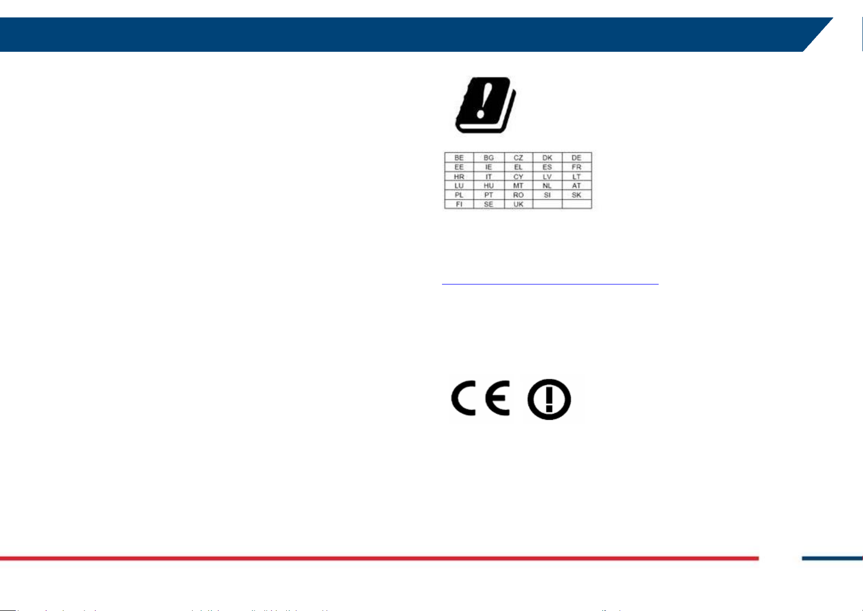
1.3 Authorization for use –national restriction
The use of HYDRA system is subject to authorization by the Competent
Ministry of the country where the system will be used.
For more details with reference to the restriction, please refer to the
following website:
https://www.efis.dk/views2/search-general.jsp
1.4 CE Marking
This equipment is in compliance with the
essential requirements and other relevant
provisions of Directive 2014/53/UE.
The full Declaration of its Conformity can be
found either on the CD or a separate
document included with this product.
This is a Class A product. In a domestic
environment it may cause radio interference.
If so, the user may need to take adequate
measures.
ABOUT THE MANUAL
IDS GeoRadar S.r.l. MNG/2017/009 Rev 1.1 5/ 54
2ABOUT THE MANUAL
2.1 Manual layout
This manual is composed of several parts. After an Introduction, the first
part describes the device and its components, with the explanation of the
main features.
The second part shows the procedure to install the device and how to
configure it correctly (Assembly Procedure).
Eventually, the maintenance plan and additional information are illustrated.
2.2 Symbols
Warning information
Note information
Tip information
2.3 Glossary and acronyms
2.3.1 Acronyms
DEM Digital Elevation Model
HYDRA HYper Definition RAdar
RADAR Radio Detection And Ranging
FMCW Frequency Modulated Continuous Wave
PSU Power Supply Unit
PoE Power-over-Ethernet
HP High Power
LP Low Power
IR Infra Red
PTU Pan-Tilt Unit
USB Universal Serial Bus
AC Alternate Current
2.4 Reference
The applicable versions of the following documents are the one officially
released at the time of the emission of the present document.
[BD1] MNG/2017/010 –IBIS Guardian 3.5 –User Manual
[BD2] MNG/2017/015 –Hydra Controller - User Manual
[BD3] MNG/2017/014 –Surf Scan 1.2 –User Manual
SAFETY DIRECTIONS
IDS GeoRadar S.r.l. MNG/2017/009 Rev 1.1 6/ 54
3SAFETY DIRECTIONS
3.1 Description
The following directions enable the person responsible for the product, and
the person who actually uses the equipment, to anticipate and avoid
operational hazards.
The person responsible for the product must ensure that all users
understand these directions and adhere to them.
3.2 Definition of Use
The intended use is the monitoring, with early warning capabilities, of
movement on:
•Tunnel Walls.
•Buildings.
•Open Pit Mines.
•Landslides.
•Dams.
•Cut Slopes.
3.3 Reasonably Foreseeable Misuse
•Use of the product without instruction.
•Use outside of the intended use and limits.
•Disabling safety systems.
•Removal of hazard notices.
•Opening the product using tools, for example screwdriver,
unless this is permitted for certain functions.
•Modification or conversion of the product.
•Use after misappropriation.
•Use of products with obvious damages or defects.
•Use with accessories from other manufacturers without the
prior explicit approval of IDS GeoRadar s.r.l.
•Inadequate safeguards at the working site.
3.4 Limits of Use
DANGER: Local safety authorities and safety experts must be
contacted before working in hazardous areas, or close to
electrical installations or similar situations by the person in
charge of the product.
Environment: Suitable for use in an atmosphere appropriate for permanent
human habitation. Not suitable for use in aggressive or explosive
environments.
3.5 Responsibilities
Manufacturer of the product - IDS GeoRadar s.r.l is responsible for
supplying the product, including the user manual and original accessories,
in a safe condition.
Person responsible for the product - the person responsible for the
product has the following duties:
to understand the safety instructions on the product and the instructions in
the user manual;
to ensure that it is used in accordance with the instructions;
to be familiar with local regulations relating to safety and accident
prevention;

SAFETY DIRECTIONS
IDS GeoRadar S.r.l. MNG/2017/009 Rev 1.1 7/ 54
to inform IDS GeoRadar s.r.l. immediately if the product and the
application becomes unsafe;
to ensure that the national laws, regulations and conditions for the
operation of electromagnetics transmitters are respected.
3.6 Hazards of Use
DANGER: Because of the risk of electrocution, it is dangerous
to use poles and extensions in the vicinity of electrical
installations such as power cables or electrical railways.
Precautions:
Keep at a safe distance from electrical installations. If it is
essential to work in this environment, first contact the safety
authorities responsible for the electrical installations and
follow their instructions.
WARNING: Watch out for erroneous measurement results if
the product has been dropped or has been misused,
modified, stored for long periods or transported.
Precautions:
Periodically carry out test measurements, particularly after
the product has been subjected to abnormal use and before
and after of important measurements.
WARNING:
Precautions:
SAFETY DIRECTIONS
IDS GeoRadar S.r.l. MNG/2017/009 Rev 1.1 8/ 54
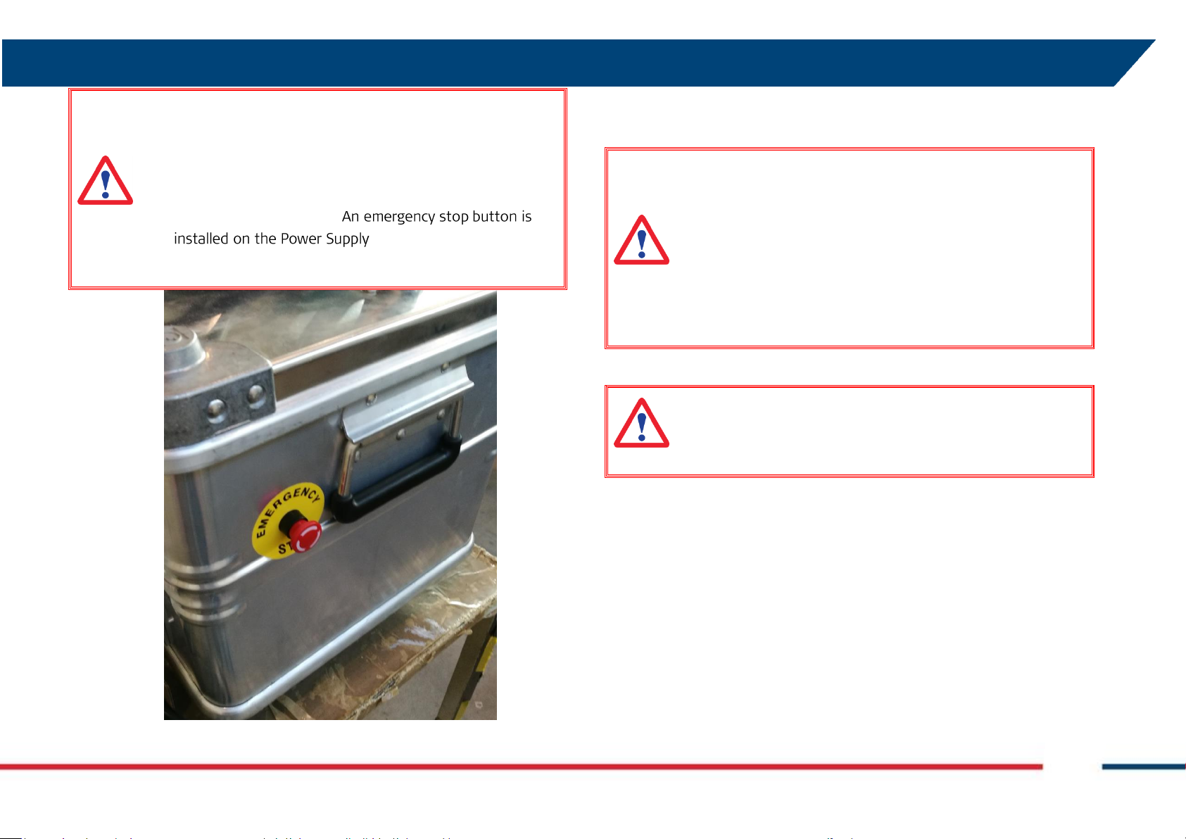
WARNING: Moving parts. Be aware of the risk of collision
with the Acquisition Unit during its movement.
Precautions:
Do not stand inside the Area of Operation (Fig. 2) during the
functioning of the system.
Unit to immediately stop the
movement in case of hazard (Fig. 1).
Fig. 1 –Emergency stop button
WARNING: Infrared laser radiation (class 1M): the laser
radiation is safe to look with the unaided eye but must not be
viewed using binoculars or other optical devices at a distance
of less than 15 m.
Precautions:
Do not use optical devices inside the Area of Operation (Fig. 2)
during the functioning of the system.
DANGER: HYDRA emits non-ionizing radiations that can cause
interference with implanted electrical or ferromagnetic devices
(such as a pacemaker).

SAFETY DIRECTIONS
IDS GeoRadar S.r.l. MNG/2017/009 Rev 1.1 9/ 54
Fig. 2 –Area of Operation
WARNING: If the product is used with accessories, for
example the Spotlight, you may increase the risk of being
struck by lightning.
Precautions:
Do not use the product in a thunderstorm.
WARNING: Inadequate securing of the working site can lead
to dangerous situations, for example in traffic, on building
sites, and at industrial installations.
Precautions:
Always ensure that the working site is adequately secured.
Adhere to the regulations governing safety and accident
prevention and road traffic.
WARNING: During dynamic applications, for example
stakeout procedures there is a danger of accidents occurring
if the user does not pay attention to the environmental
conditions around, for example obstacles, excavations or
traffic.

SAFETY DIRECTIONS
IDS GeoRadar S.r.l. MNG/2017/009 Rev 1.1 10/ 54
WARNING: Only IDS GeoRadar authorized technical service
are entitled to repair these product.
WARNING: High mechanical stress, high ambient
temperatures or immersion into fluids can cause leakage, fire
or explosions of the batteries.
Precautions:
Protect the batteries from mechanical influences and high
ambient temperatures. Do not drop or immerse batteries
into fluids
DANGER: The use of the system in explosive environments
such as gassy mines is strictly forbidden. The non-ionizing
radiations can interfere with devices such as detonators and
cause explosions.
WARNING: If the product is improperly disposed of, the
following can happen:
• If polymer parts are burnt, poisonous gases are produced
which may impair health.
• If batteries are damaged or are heated strongly, they can
explode and cause poisoning, burning, corrosion or
environmental contamination.
• By disposing of the product irresponsibly you may enable
unauthorized persons to use it in contravention of the
regulations, exposing themselves and third parties to the risk
of severe injury and rendering the environment liable to
contamination.
WARNING: During the maintenance of the system always
switch off the system and disconnect it from the power
source.
WARNING: Always perform the maintenance and regulation
of the system with steady Acquisition Unit. Performing these
operations with the system moving can cause hazards.

SAFETY DIRECTIONS
IDS GeoRadar S.r.l. MNG/2017/009 Rev 1.1 11/ 54
Precautions:
RECYCLING
The crossed out wheeled bin symbol shown on the equipment
indicates that the product must be recycled separately from
other waste at the end of its useful life.
Separate waste disposal of this product at the end of its useful
life will be organised and managed by IDS GeoRadar. When you
decide to dispose of the equipment, contact IDS GeoRadar and
follow the system that IDS GeoRadar has set up to permit the
separate collection of the apparatus at its life end.
Adequate separate collection for its subsequent recycling,
treatment and environmental friendly disposal contribute
towards avoiding any unnecessary effects on the environment
and to health and favour the reuse or recycling of the materials
that make up the equipment. Unauthorised disposal of this
product as unsorted waste by its possessor will lead to an
administrative penalty foreseen by national regulations.
WARNING: If the accessories used with the product are not
properly secured and the product is subjected to mechanical
shock, for example blows or falling, the product may be
damaged or people can sustain injury.
Precautions:
When setting-up the product, make sure that the accessories
are correctly adapted, fitted, secured, and locked in position.
Avoid subjecting the product to mechanical stress

GENERAL DESCRIPTION
IDS GeoRadar S.r.l. MNG/2017/009 Rev 1.1 12/ 54
4GENERAL DESCRIPTION
The HYDRA system is designed to provide real time displacement
information with an accuracy of a tenth of a millimeter. The HYDRA system
is particularly suitable for a range of applications depending on the
configuration:
•Hydra G HP for Slope Monitoring: it is capable to detect and
measure both slow and fast movements in various different
environments, like for example Quarries, Open pit mines,
Landslides and Cut-slopes;
•Hydra G LP for Building Monitoring: with its all-in-one software
package, Surf Scan, it permits fast movement detection of a
Building, for example during the foundation consolidation process;
•Hydra U for Tunnel Monitoring: it aims to monitor rock fall
precursory event and provide warning in advance to evacuate
people and machinery at risk.
All the Hydra configurations operate at the same frequency.
The performance of the HYDRA system depends on the operative
measurement conditions (above all, related to the reflectivity of the area
under investigation); however, the best performance characteristics can be
defined as follows, depending on the configuration and type of antennas.
4.1 System Configurations
Hydra G HP with ANT 101:
▪Maximum operational distance: 800 m;
▪Image resolution in distance: 0.2 m;
▪Angular resolution: 14 mrad;
▪Accuracy in measuring displacements in the viewing direction: 0.1
mm;
▪Radiation Cone (without considering the Pan-Tilt Movement): 16° H
× 13° V;
▪Angular coverage (thanks to the Pan-Tilt Movement): 120°.
Hydra G HP with ANT 102:
▪Maximum operational distance: 500 m;
▪Image resolution in distance: 0.2 m;
▪Angular resolution: 8 mrad;
▪Accuracy in measuring displacements in the viewing direction: 0.1
mm;
▪Radiation Cone (without considering the Pan-Tilt Movement): 26° H
× 25° V;
▪Angular coverage (thanks to the Pan-Tilt Movement): 120°.
Hydra G LP:
▪Maximum operational distance: 300 m;
▪Image resolution in distance: 0.2 m;
▪Angular resolution: 14 mrad;
▪Accuracy in measuring displacements in the viewing direction: 0.1
mm;
▪Radiation Cone (without considering the Pan-Tilt Movement): 16° H
× 13° V;

GENERAL DESCRIPTION
IDS GeoRadar S.r.l. MNG/2017/009 Rev 1.1 13/ 54
▪Angular coverage (thanks to the Pan-Tilt Movement): 120°.
HYDRA-U:
▪Maximum operational distance: 200 m;
▪Image resolution in distance: 0.2 m;
▪Angular resolution: 8 mrad;
▪Accuracy in measuring displacements in the viewing direction: 0.1
mm;
▪Radiation Cone (without considering the Pan-Tilt Movement): 26° H
× 25° V;
▪Angular coverage (thanks to the Pan-Tilt Movement): 120°.
4.2 System Features
Some of the features of the HYDRA system are:
▪Permits the operator to perform remote monitoring of the area
(remote sensing), without needing to access the critical area;
▪Supplies a continuous displacement map of the entire area. The
HYDRA system simultaneously measures all the displacements of the
entire area illuminated by the antenna beam;
▪Directly measure the displacements of the territory of interest in real
time;
▪It can be used also in dark conditions providing a visual feedback
thanks to its infrared camera (except HYDRA G LP model);
▪Permits the autonomous DEM reconstruction of the monitored area,
without the need of an external model of the terrain (only for HYDRA
U model);
▪Permits the positioning of each monitored point directly on an image
from the Camera (only for HYDRA G LP model)
▪It doesn’t require the continuous presence of an operator and can be
remotely controlled through Ethernet connection;
▪It can be deployed in less than 30 minutes and it can be transported
by a single person.

GENERAL DESCRIPTION
IDS GeoRadar S.r.l. MNG/2017/009 Rev 1.1 14/ 54
4.3 System Composition
The main components are:
▪Radar Sensor: this generates, transmits and receives the
electromagnetic signal. The Radar Sensor is installed on the Pan-Tilt;
▪Positioning Unit, made of a Pan-Tilt Unit (PTU) and a metallic arm to
hold the Radar Sensor. The movement of the Radar Sensor on the
PTU permits the utilization of an Arc-SAR technique, that obtains a
two dimensional image of the scenario;
▪Tripod unit, for the installation of PTU;
▪Power Supply Unit (PSU): supplies power to the system through the
batteries. Mains supply is used to load the batteries. Embedded in
the PSU there is the control computer, equipped with the system
management software. This is used to configure the acquisition
parameters, manage measurements and transmit data to the control
room;
▪Camera: provides a panoramic view or shots of the monitored area;
in case of HYDRA U and HYDRA G HP model it also have IR capabilities
to work during the night or in darkness.
▪IR Laser (only for HYDRA U model): installed on the PTU, act as a laser
scanner to reconstruct the surface of the monitored area, on which
are projected the radar data.
▪Cables: Hydra is supplied with 3 cables, a Main Cable connecting the
Power Supply Unit to the Pan-Tilt Unit, a Camera Ethernet Cable, and
a Power Cable connecting the PSU to the main power line.
▪Optional components: The HYDRA system can be integrated with two
optional components, a Siren Alarm and a Spotlight.
A detailed description of each component is reported in Chapter 5.
Fig. 3 –Composition of the HYDRA system
SYSTEM BREAKDOWN
IDS GeoRadar S.r.l. MNG/2017/009 Rev 1.1 15/ 54
5SYSTEM BREAKDOWN
The Hydra system is composed by:
•Hydra Radar Sensor (see Par. 5.1);
•Antennas (see Par. 5.2);
•Pan-Tilt Unit (see Par.5.3);
•Tripod (see Par. 5.4);
•Power Supply Unit (see Par. 5.5);
•Tablet (see par. 5.6);
•Camera (see Par. 5.7);
•Laser, only for Hydra U model (see Par.5.8);
•Cables (see Par. 5.9);
•Siren Alarm, optional (see Par. 5.10);
•Spotlight, optional (see Par. 5.11).
5.1 HYDRA Radar Sensor
The Radar Sensor (Fig. 4) is the unit containing all the parts for the
generation, transmission, reception and acquisition of the radar signal.
The HYDRA Radar Sensor has the following interfaces:
•n. 14 threaded holes for the installation of the antenna cover (Fig. 5);
•n. 2 waveguides for installation of the antennas (Fig. 5);
•n. 1 connector 19 pins to Pan-Tilt cable (Fig. 6);
•n.1 connector 4 pins for Laser cable (Fig. 6);
•n.1 connector 3 pins for Trigger cable (Fig. 6);
•n.3 fixing points for Positioning Unit (Fig. 7);
•n.1 Radome protective cover (Fig. 4).
Fig. 4 –HYDRA Radar Sensor (front view)
Radome protective cover

SYSTEM BREAKDOWN
IDS GeoRadar S.r.l. MNG/2017/009 Rev 1.1 16/ 54
Fig. 5 –HYDRA Radar Sensor (front view without cover)
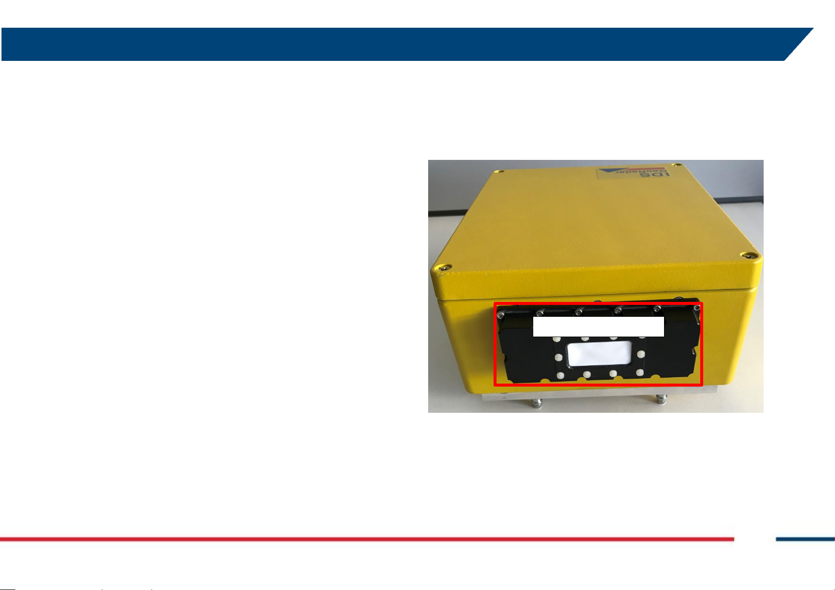
Fig. 6 –HYDRA Radar Sensor (back view)
Threaded holes for
Antenna Cover
Antennas mounted on
the Waveguides
Trigger cable
connector
Sensor cable
connector
Laser cable
connector

SYSTEM BREAKDOWN
IDS GeoRadar S.r.l. MNG/2017/009 Rev 1.1 17/ 54
Fig. 7 –HYDRA Radar Sensor (bottom view)
5.2 Antennas
The HYDRA system is provided with a couple of HYDRA-ANT 101 and/or a
couple of HYDRA-ANT102 antennas (depending on the configuration)
operating in vertical polarization and characterized by a maximum gain of
21 dBi (for ANT 102) or 17.3 dBi (for ANT 102). The amplitude
characteristics of the antenna main lobe at -3 dB and -10 dB are provided in
Tab. 2 and Tab. 2.
HYDRA-ANT101
HORIZONTAL PLANE
VERTICAL PLANE
-3 dB
16°
13°
-10 dB
32°
26°
Tab. 1 –Main lobes width of HYDRA-ANT101 antennas at -3 dB and -10 dB
HYDRA-ANT102
HORIZONTAL PLANE
VERTICAL PLANE
-3 dB
26°
25°
-10 dB
60°
55°
Tab. 2 –Main lobes width of HYDRA-ANT102 antennas at -3 dB and -10 dB
Fixing points

SYSTEM BREAKDOWN
IDS GeoRadar S.r.l. MNG/2017/009 Rev 1.1 18/ 54
Fig. 8 –HYDRA-ANT 101
Fig. 9 –HYDRA-ANT 102
The Radar Sensor is fitted with two waveguides, each with four threaded
holes, for the installation of the pair of antennas (Fig. 5).
HYDRA antennas are protected by a Radome protective cover (Fig. 7).
5.3 Positioning Unit
The Positioning Unit (Fig. 10) consists of:
•The Pan-Tilt main body, made in aluminum and plastic, with
dimensions 32x20x21 cm and weight <10 kg, capable of moving the
Radar Sensor in azimuth and elevation;
•A Triggering Magnetic Sensor to synchronize the Pan-Tilt rotation and
the radar acquisition;
•The Arc SAR arm 50 cm long holding the payload items;
•An Elevation Pointing System that is the support of HYDRA Radar
Sensor and permits the main beam of the antenna to be orientated
in elevation towards the area to be observed.

SYSTEM BREAKDOWN
IDS GeoRadar S.r.l. MNG/2017/009 Rev 1.1 19/ 54
Fig. 10 –Pan-Tilt Unit
The elevation pointing system is fixed on the Arc SAR arm through 2 cam
levers and 2 knobs. The cam levers are the rotation fulcrums of the pointing
system, while the knobs permit to select different Radar Sensor bearings,
between -30° and +30° (see Fig. 11). In Hydra-G LP configuration the
Elevation Pointing System must always be positioned at 0°; in Hydra-G HP
and Hydra U configuration the position must be the same of the Camera
tilting angle (see Par.5.7).
Fig. 11 –Elevation Pointing System
2 screw holes under the elevation pointing system permits the installation
of IR Laser under the Elevation Pointing System (see Fig. 12).
PTU
Arc SAR arm
Elevation
Pointing System
Triggering Sensor

SYSTEM BREAKDOWN
IDS GeoRadar S.r.l. MNG/2017/009 Rev 1.1 20/ 54
Fig. 12 –Screw Holes for Laser installation
On the Elevation Pointing System there are 3 fixing point to hold the sensor
in place, two of them are composed by a pull-tab, the third uses a knob (see
Fig. 7).
The PTU must be connected to the Power Supply Unit (PSU) with the Main
Cable, attached to the 32-pins connector (Fig. 13):
Fig. 13 –32-pins connector for the Main Cable
Depending on the system configuration, the function of the Positioning Unit
is different:
•For Hydra-U, the PTU is used to move the Laser in azimuth and
elevation to perform surface reconstruction and the Radar Sensor
in azimuth for the actual monitoring. During surface reconstruction
the PTU moves performing a serpentine, alternating clockwise and
counterclockwise scans in azimuth, increasing the elevation angle
at each scan. During the actual scan, instead, the PTU moves in
azimuth at a fixed elevation from -60° (the magnetic trigger angle,
see Fig. 14) to +60° clockwise, and then returns to the magnetic
trigger angle (counterclockwise).
This manual suits for next models
3
Table of contents


