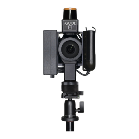
iGUIDE IMS-5 Operator's manual

IMS-5 Camera System
System and Software Documentation
Revision 1.22

iGUIDE® IMS-5 Camera System:
System and Software Documentation
Table of contents
Regulatory Information 3
Camera System Overview 4
Camera System Components 5
Camera Handling 6
Tripod Setup 6
Connecting to Camera 8
Collecting Data With Survey 9
Create a Project and Floor 10
Turn Laser ON 10
Shooting Panoramas 11
Getting Best Results From Auto Settings 12
Important Shooting Notes 12
Taking Still Pictures 14
Additional Shooting Tips 14
Summary of Survey Controls and Indicators 14
Summary of Manage Tab 16
Automatic Mapping Mode (Advanced) 18
Automatic Mapping Tips 19
Outdoor and Common Area Scans 20
Processing Data With Stitch 22
About iGUIDE Images 22
Stitch Workflow 23
User Interface 23
Project Tree View 23
Adding User Panoramas 25
Toolbar Buttons 25
Data Quality 30
Maintenance 34
Fisheye Lens Cleaning 34
Laser Scanner Optical Window Cleaning 34
1

Compass Calibration 34
USB Flash Drive 35
Factory Reset 35
Firmware Update 35
Troubleshooting 35
Wi-Fi connectivity 35
Survey browser compatibility 36
Removing reflections in mirrors 36
Ball head drift 36
Miscellaneous Survey issues 36
Wrong camera rotation direction 36
Battery Charging 37
Specifications 38
Canon EOS Rebel T100 Menu Settings 39
2

Regulatory Information
This product has been tested and was found to comply with the following standards:
· FCC PART 15, SUBPART B, Class B - Unintentional Radiators.
· Industry Canada ICES-003, Issue 6, Class B - Information Technology Equipment.
· CISPR 11:2009 + A1:2010 / EN 55011:2009 +A1:2010, Class B - Industrial, Scientific and Medical Equipment.
· EN 61326-1:2013 – Electrical Equipment for Measurement, Control and Laboratory Use - EMC Requirements, Part 1:
General Requirements.
This product includes a laser scanner which is a Class 1 laser product and complies with IEC 60825-1 2007-03 Ed. 2.0 and
21 CFR Subchapter J Parts 1040.10 and 1040.11 except for deviations pursuant to Laser Notice No. 50, dated June 24,
2007.
This device complies with Part 15 of the FCC Rules. Operation is subject to the following two conditions: (1) this device
may not cause harmful interference, and (2) this device must accept any interference received, including interference that
may cause undesired operation.
NOTE: This equipment has been tested and found to comply with the limits for a Class B digital device, pursuant to part 15
of the FCC Rules. These limits are designed to provide reasonable protection against harmful interference in a residential
installation. This equipment generates, uses and can radiate radio frequency energy and, if not installed and used in
accordance with the instructions, may cause harmful interference to radio communications. However, there is no
guarantee that interference will not occur in a particular installation. If this equipment does cause harmful interference to
radio or television reception, which can be determined by turning the equipment off and on, the user is encouraged to try
to correct the interference by one or more of the following measures:
· Reorient or relocate the receiving antenna.
· Increase the separation between the equipment and receiver.
· Connect the equipment into an outlet on a circuit different from that to which the receiver is connected.
· Consult the dealer or an experienced radio/TV technician for help.
The product modifications not expressly approved by Planitar could void the user's authority to operate the equipment
under FCC rules.
This product includes a Wi-Fi USB adapter that has been evaluated to meet general RF exposure requirement. The device
can be used in portable exposure condition without RF restriction.
This product is Class B, Group 1 ISM equipment according to CISPR 11. Group 1 ISM product: A product in which there is
intentionally generated and/or used conductively coupled radio-frequency energy which is necessary for the internal
functioning of the equipment itself. Class B products are suitable for use in domestic establishments and in
establishments directly connected to a low voltage power supply network which supplies buildings used for domestic
purposes.
Contact Planitar at www.planitar.com or Planitar authorized distributor for product disposal information and product
take-back program.
3

Camera System Overview
The iGUIDE Camera System is a unique camera system that measures a space while
simultaneously photographing it.
Figure 1 shows the main components of the camera system. The camera system uses a laser
scanner for gathering laser measurement data and a DSLR camera with a fisheye lens for
shooting ultra wide-angle HDR images that are later stitched into 360-degree panoramas. The
scanner's laser is infra-red and is invisible. Each DSLR camera and lens assembly is factory
calibrated to allow accurate rectification of fisheye images and their alignment and stitching into
cubic panorama tiles. It is important to handle the camera with care to keep the alignment of the
optical assembly intact. The camera is not user serviceable and must not be disassembled or the
warranty will be void. The camera has a built-in Wi-Fi access point and you can connect to it from
any Wi-Fi enabled device. It is controlled by the Survey web app that runs in a web browser. Phones
and tablets with a 5-7 inch screen are most convenient for use with the camera.
Figure 1. Camera components.
4

Camera System Components
The system controller is the black box on the side of the camera system. On top you will find the
power button used to turn the system on.
The system battery is located on the side of the camera directly opposite the system controller. It
doesn’t need to be removed to be charged and has a charge level indicator on top of the battery
itself.
The USB flash drive where all the data is stored is also plugged into the system controller. It is
located under the DSLR body.
The panoramic rotator is located at the bottom of the camera system and must be connected to a
tripod or quick release plate prior to shooting.
The bubble level can be seen on top of the DSLR body and is used to level the camera.
5

Camera Handling
The camera should be handled by the panoramic rotator and can be additionally supported by a
grip onto the system controller. For lens cleaning, the camera can be placed on a table with the
fisheye lens facing up and the DSLR camera LCD screen facing down, see Figure 2.
The system battery and the DSLR camera battery must be charged before the first use. It is
convenient to charge the system battery while the camera is placed in the carrying case. The system
battery charging port is located at the bottom of the battery holder. Consult the Troubleshooting
section of this manual for the procedure for charging a completely discharged battery.
Figure 2. Camera handling.
Tripod Setup
A tripod is not included with the camera and must be supplied by the user. A tripod with a ball head
is recommended to allow for easy leveling of the camera. It is also recommended to use a ball head
with a quick release (QR) plate for easy installation of the camera on the tripod. The camera weight
is 2.4 kg (5.2 lb). The center of gravity of the camera is offset from the panoramic rotator axis, so it
is recommended to use a ball head and a tripod with a load capacity of at least 5 kg (11 lb).
The tripod height should be adjusted so that the fisheye lens is about 120cm (4 ft) above the floor to
allow visually capturing the surfaces of kitchen counters and islands. Raising the camera too high
will cause capturing too much of a ceiling.
6

It is recommended to extend the tripod column at least 10cm (4") to provide enough space for a
convenient hand grip, see Figure 3. Raising the column higher will result in too much sway of the
camera under its weight when the camera is rotated and will negatively affect quality of panorama
alignment and stitching.
A foam cushion disk is provided with the camera and can be installed on the tripod column
beneath the ball head and above the hand for a more comfortable grip.
Figure 3. Tripod handling.
7

Connecting to Camera
The camera is powered on and off by the power button located the top of the system controller. The
camera boots in less than 10 seconds, so there is no Sleep mode.
After the power LED turns green, navigate to your phone or tablet Wi-Fi settings and connect to the
Access Point named planitar-xxxxxx, where xxxxxx is a unique code for each camera. The default
Wi-Fi password is p1234567.
After successful connection, open a web browser and type URL http://192.168.5.1 in the address
field. The browser will load the Survey web app that controls the camera. In the Survey app,
navigate to the Manage tab and change the default Wi-Fi password. It is also recommended to save
the Survey web app URL as a bookmark to your home screen for easy launching of Survey in full
screen mode.
You can access the camera's USB Flash drive over Wi-Fi from your Mac or PC desktop computer
once you connect to the camera from the desktop computer over Wi-Fi. Open Windows Explorer or
Mac Finder and browse the network for a computer named planitar-ims. If a login dialog is
presented, use login name guest with a blank password.
To conserve battery, the laser scanner will power off if there is no communication between Survey
and the camera for more than 2 minutes. Additionally, the camera system will power off
automatically if no user interaction occurs with the Survey app for 20 minutes. This default Power
Off timeout can be changed or completely disabled through the Manage tab in the Survey app.
To shoot panoramas you will also have to turn the DSLR power switch to the ON position.
IMPORTANT
• Do not leave a discharged system battery in the camera for long periods of time, e.g. for more than
a week with one bar of charge on the battery's LCD display. Completely charged battery can remain
in the camera for up to two years.
• Do not support the camera by holding onto the system battery.
• Do not unplug Wi-Fi USB dongle while the system is powered up.
• Do not unplug USB Flash drive until it is first Safely Removed in the Survey app or the system is
powered off.
• If using another USB Flash drive, ensure it is slim enough and can be inserted completely into the
USB connector. It is recommended to use USB3 drives for faster image writing speed.
• The system must be powered off when charging the system battery.
• The mode dial on the DSLR camera must always be set to the M position.
• Do not change DSLR camera menu settings from the values configured by Planitar.
8

Collecting Data With Survey
The Survey user interface is shown in Figure 4. There are five tabs: Survey, Pano, Floor, Project,
and Manage. Each tab represents a separate screen and functions that can be returned to at any
time. Most of the time is spent working in the Survey tab than any other.
Figure 4. Survey tab.
Data collection for Planitar iGUIDEs involves using the camera to scan a property and capture
fisheye images in every room to create panoramas. The integrated laser scanner collects
measurement data for every room which forms a map of the space during the shooting of
panoramas. The camera is rotated manually on the panoramic rotator into 3 angular positions
spaced 120 degrees apart to make a 3-shot pano. The camera can be controlled from any phone or
9

tablet over Wi-Fi through the Survey web application running in a web browser. Collected data and
images are saved to a USB Flash drive attached to the camera.
After house data has been collected, it needs to be transferred from the camera to a desktop
computer either on the USB Flash drive or over Wi-Fi. The data is then loaded into Stitch
application running on a desktop computer where panoramas are aligned and stitched
automatically. The Stitch application allows manual adjustments to panorama alignment and color,
as well as fine-tuning of room positions and floor layout before the iGUIDE data is exported and is
ready for upload to the online iGUIDE Portal. Planitar processes the uploaded data to create floor
plans from measured data and assemble panoramas and floor plans into a complete iGUIDE.
Create a Project and Floor
To begin shooting a property you will have to name it and select a floor to start on. Each floor is
captured separately and floor creation will occur for every space in a home that requires its own
floor plan. Follow the steps below to begin:
1. Switch to the Project tab.
2. Type a project name for the new house.
3. Enter exterior wall thickness (may not be needed for apartments).
4. Press the Create button.
5. Switch to the Floor tab.
6. Enter a floor name or select a predefined name from the drop-down list.
7. Select grade not set to select a grade level.
8. Enter exterior wall thickness for the floor (if required).
9. Press the Create button.
Exterior wall thickness should be measured with a tape measure at the main entrance or should
be estimated. For floors with no main entrance the wall thickness will have to be measured at a
window. Entering exterior wall thickness for each floor individually is optional and if not provided,
the wall thickness entered for the project will be used. Sufficient accuracy for exterior wall
thickness measurement or estimation is about 1cm or 0.5 inch. The value of the exterior wall
thickness will be used to compute and report the Exterior Floor Area in the iGUIDE Report and on
PDF floor plans delivered with the iGUIDE.
Grade level will affect total area calculations. By default above grade will be included in the total
exterior area calculations and below grade will be excluded from it. Check requirements in your
area for what is considered above or below grade.
Turn Laser ON
10

If not using the advanced AutoMap mode (described later), ensure the button labeled Mode reads
Track. The laser scanner has to be turned on by tapping the button labeled Laser. This must be
done prior to capturing any images if measurement data is required. If the laser scanner is not
turned on there will be a warning message asking you to do so or proceed with no measurements.
Shooting Panoramas
You will need to shoot a panorama for every space in the home. This includes spaces that would
typically not be photographed like storage spaces, walk in closets, large pantries, utility rooms,
hallways, and landings. If any space is left uncaptured the drafting team will not be able to draw
floor plans. Details such as doors, windows, fixtures, and appliances need to be visible in the
panoramas so that the drafting team can see and include them on the floor plan. Some small spaces,
such as closets and pantries can be drafted using surrounding walls, so you do not need to go in.
To shoot a panorama follow the steps below:
1. Turn the DSLR camera On and ensure Canon mode dial is in M position.
2. Place the camera in a suitable location for a panorama.
3. Press the "+1" button to create a new panorama.
4. Check that the rotator is firmly clicked into position.
5. Level the camera using the hot-shoe bubble level and the ball head. Precise leveling is not
required as Stitch will auto-level panoramas during post-processing.
6. Turn On the LiveView mode on the DSLR camera if not using Auto Exposure.
7. Adjust white balance in Survey by choosing a preset from the drop-down list (e.g. Daylight,
Tungsten, Fluorescent, Auto). Use Auto if you prefer to let the camera decide - Stitch will later
correct any jumps in white balance between the three fisheye images of the same pano.
8. Adjust exposure (shutter time) using the control wheel on the DSLR camera while watching the
DSLR camera LCD screen. You can refer to the on screen histogram to avoid over-exposure. Or you
can turn on Auto Exposure if you prefer to let the camera optimize the exposure.
9. Tap the Panorama button to shoot. Unless HDR mode is turned Off, three exposure bracketed
images will be taken and fused into an HDR image right away. Several HDR bracket presets are
available and custom EV bracket values can be configured in the Manage tab. If Auto Exposure is
used, it will take couple seconds to optimize the exposure, but this is done only for the first position.
10. HDR processing is performed in background and you can take new shots without waiting for it
to finish. When ready, processed shots will be displayed if the active pano remains the same. While
the camera is busy, green LED will blink and power off button will be ignored.
11. Rotate the camera clockwise to the second and third positions and take a shot at each position.
12. Examine the data by maximizing the map view. Tap the Move button under the heading Pano,
move and rotate laser scan (room outline) on screen, to align with earlier scans, then tap the Save
button to freeze it in place. Moving is done by dragging one finger on screen and rotating is done by
dragging two fingers.
13. Repeat the above steps for other panoramas on the floor.
11

14. Before leaving a floor, enable the Coverage view (its slider is found in the upper left corner of
the screen when the map is maximized) to display floor coverage by panoramas and see if any
rooms were missed.
15. After you finish gathering data for a floor, go to the Floor tab, create a new floor and repeat
shooting steps for each level of the home. You can always return to an existing floor to add more
panoramas.
Getting Best Results From Auto Settings
It is recommended to use use Auto white balance and Auto Exposure. Together they produce best
results most of the time, except difficult situations where manual intervention may be required.
When using Auto Exposure, point the camera toward the largest brightest area in the room for the
first position.
Examine the resulting image once it has loaded and adjust HDR brackets if needed and re-shoot.
If Auto white balance and exposure did not produce desired results, you can always adjust
exposure and white balance manually and re-shoot.
Examine the image for any reflections of you in the mirrors or other people in the picture and
reshoot if needed.
If you need to re-shoot, move the green square shot selector in the top left of the screen to correct
shot position by tapping on it. Also examine the resulting laser data for any signs that the tripod or
rotator was misaligned or bumped. More details on misaligned data can be found in the Data
Quality section.
Important Shooting Notes
All floors must be measured and shown in panoramas in their entirety for the drafting team to be
able to draft them. Partially mapped or photographed floors will not be drafted. Refer to
iGUIDE Drafting Standard found on the iGUIDE Portal Support section for more information.
Some panoramas will need to be shot for drafting reference only. They can be selectively disabled in
the iGUIDE later if desired. It is possible to shoot only one fisheye image resulting in a partial
panorama if it is only needed for reference. In this case you can ignore the warning about
incomplete panorama when creating a new panorama after that. Partial panoramas will not be
viewable in iGUIDE. Most common usage for partial panoramas is for measuring depth of closets
where back wall is not measurable otherwise. Remember that every room should have at least one
full panorama, so that the drafting team can properly place doors, windows, and other objects.
12

You can skip surveying complete floors, such as basements if you do not intend to be showing them
in the iGUIDE. Reported Total Interior and Exterior Floor areas for the house will be affected,
however.
If the Laser is On, each panorama scan will be saved separately from the AutoMap (if using the
advanced AutoMap mode explained later) and panorama laser scan data will be shown in blue
color. It is possible to move and rotate panorama scans independently from each other and from the
AutoMap.
Exposure, white balance (when not using Auto), as well as camera leveling, and tripod position
must be kept the same for all three shot positions, otherwise panorama stitching will be negatively
affected.
When shooting with HDR, you may see over-exposed areas turn grey in the resulting HDR image.
This typically occurs on floors and ceilings between the camera and a bright window. Reduce the
exposure for the main image and re-shoot. You can use histogram on the DSLR camera LCD screen
as an aid – try to avoid having too many peaks at the right edge of the histogram. Using Auto
Exposure helps to avoid such image artifacts in most cases.
When shooting panoramas outside, it is the camera may not be able to measure. You will need to
manually position and rotate panorama locations using the Move Pano mode.
After all three shots for a panorama are completed, the camera checks measured compass angles
for proper spacing and may warn you if this check fails. It may happen due to close proximity to
massive steel objects, such as steel door frames. If that happens very frequently, you may want to
re-calibrate the compass. If the angle checks fail in every panorama of the project, the compass
orientation on the iGUIDE will need to be set manually through the iGUIDE Portal.
You can choose an existing panorama through the Pano tab to make it active. The active panorama
can be moved on the map, its data can be overwritten, and its images can be viewed.
Custom HDR exposure bracketing values can be set the Manage tab. The typical Indoor HDR preset
has the underexposed image at -5EV to capture scenes behind windows and the overexposed image
at +2EV to capture dark corners. If you find that the main image exposure needs to be set
significantly shorter to avoid grey areas in the HDR image, you can increase the longer exposure
setting (+EV), e.g. go from +2EV to +3EV. If you find that windows are too washed out, you can
decrease the shortest exposure (-EV) setting, e.g. go from -5EV to -7EV.
The "+1" button will create numbered panorama folders on USB disk. Use the Pano tab if you need
to name panoramas with descriptive names for easier identification during your post-processing.
13

You can type a custom name or choose a pre-defined name. When using pre-defined names
repeatedly, they will get an auto incrementing numbering, e.g. Bedroom 1, Bedroom 2, etc.
There is no Delete Pano action, you can simply overwrite the data to re-use the panorama location.
Taking Still Pictures
If you want to take a still picture for the iGUIDE image gallery, reposition the camera and tap the
Still Image button to take one fisheye image instead of a panorama. You do not need to use the "+1"
button for still images, the camera will create and name image folder automatically. A still image
can be captured from the single fisheye image later in Stitch.
Additional Shooting Tips
Default ISO setting is 200. You can change it as needed on the DSLR camera itself and Survey will
not override it. It is not recommended to set ISO higher than 400 or to set it to Auto.
Turn on all the lights, especially pot lights and local lights.
If a room has large windows, set white balance to the Daylight setting. If pre-dominant lighting
comes from incandescent light bulbs or warm yellowish fluorescent lighting, use the Tungsten
setting. For cold white fluorescent lights use the Fluorescent setting. Finer control of white balance
is available in Stitch application. It is recommended to use Auto white balance.
You can disable HDR to speed up shooting when capturing evenly illuminated areas such as
basements or when shooting reference panoramas.
For panoramas, the optimal position of the camera in a room depends on the room size. For smaller
bedrooms the optimal position is about 1m (3ft) away from the door towards the center of the
room.
Objects in panoramas appear very small at distances over 5m (15ft), so in larger rooms it is
recommended to shoot additional panoramas.
For still pictures, it is best to put the camera all the way into a corner or in the door opening.
Still pictures extracted from fisheye images have limited resolution of about 2 megapixels. Use a
second camera with a wide-angle lens if you require high-resolution images for print.
You can turn the Laser off to conserve the system battery when shooting common areas in an
apartment building that will not require a floor plan or when shooting panoramas outside.
14

Summary of Survey Controls and Indicators
System battery indicator shows the system battery charge level and remaining time. The DSLR
camera battery indicator shows the remaining charge level in three discrete steps, approximately
corresponding to 80%, 50% and 30%.
The text in the bottom right corner shows the house, floor, and panorama names.
Laser scanner switch. Turn laser scanner on or off.
Auto exposure switch. Turn auto exposure on or off.
Laser scanner mode selector. Tap to switch between AutoMap and Track modes.
Move scan. Move current laser scan (camera position) on the map.
Move pano. Move currently selected panorama on the map.
Map Actions selector. Available actions: Undo AutoMap, Re-center Map, Grow
Canvas, Erase AutoMap, Merge Scan. Some actions may be hidden depending on context.
Shoot panorama. Shutter button for shooting panoramas. Shot position will advance
automatically on each shutter release. The button is red when DSLR camera is powered off.
Shoot Still image. Shutter button for shooting a still image for gallery. The button is red when
DSLR camera is powered off.
White balance/Color temperature selector. Exposes settings from Canon DSLR.
15

HDR mode selector. Turn HDR off, select between several HDR bracket presets
(Indoor, Outdoor, Beach) or use Custom HDR bracket configurable through the Manage tab.
Currently used HDR bracket -/+EV values are shown in the upper right corner of the screen.
New panorama location. Creates a new folder on USB disk in the current floor folder to store
panorama images. Folders will have incremental numbering. For custom folder naming use the
Pano tab.
Page reload. Force reloading of Survey app in browser.
Coverage switch. When turned on, coverage of the floor by panoramas will be
displayed where every panorama will be shown shaded. Use it to check if you missed any rooms.
Normally the Coverage option should be turned off, as it slows down screen updates.
Summary of Manage Tab
Figure 5. Manage tab.
Mute beep on user actions
Check the box the mute the beep that occurs after a panorama is taken or another action is
completed.
HDR Custom bracket values
16

The values entered here will affect the custom preset selection found on the Survey tab. Values
range from -1 to -7 and +1 to +7.
17

Safely Remove USB Drive
Tapping this button will disconnect the usb drive from the system software. Use this button when
removing the usb drive while the camera is running to prevent data loss or corruption.
Power Off
The camera can be powered off remotely by tapping this button.
Calibrate Compass
The camera has built in compass that is used for various functions. The compass may need to be
calibrated if frequent warnings occur. Follow the calibration procedure
Calibration How-to Video
Watch this video to learn the compass calibration procedure. The video is stored on the camera and
can be viewed at any time.
Format USB Drive
You can format the usb drive while it is inserted into the camera. This can be used as a quick way to
delete all the project data from the USB drive.
IMPORTANT NOTE: This will delete all the data from the USB drive permanently. Please be
sure to backup all important data before formatting.
HDR Midlevel
Changing this setting will affect the brightness of the final HDR images.
AutoExp Target
Auto exposure will adjust the shutter speed automatically based on the available light in a space.
The AutoExp target is a value that will affect the shutter speed and the brightness of the final
images. Decrease this value for darker images and increase for brighter images. Once this value is
set it will apply to all images taken by the camera from that point onward.
Access Point Name
Change the WiFi access point name to something other than the default.
18

WiFi Password
Change the WiFi password used to log into the camera’s WiFi hotspot.
WiFi Channel
The WiFi channel can be changed to avoid problems when interference is encountered. Acceptable
values range from 1 to 11 and Auto.
Power Off Timeout
Specify the length of time the camera will wait, while inactive, before automatically powering off.
Reset to Factory Settings
Reset all settings back to their factory default values.
Update System File
Update the camera’s system file when a new one is available. A new system file is provided by
Planitar and is available upon request.
Update Firmware
Update the camera’s firmware when a new version becomes available.
System Information
Firmware version and camera serial number are displayed.
Save System Log
A log of system activity can be saved to the USB drive.
Automatic Mapping Mode (Advanced)
Once the Laser is switched On, the camera can be in two modes – AutoMap or Track. Automatic
mapping mode (AutoMap) will allow the camera to map the house as you walk around while at the
same time tracking the camera's position. This mode is optional and is for advanced users only.
You can incorporate automatic mapping mode into your workflow once you are comfortable with
capturing panoramas. The map data gathered in this mode is used for room positioning and
19
Other manuals for IMS-5
1
Table of contents
Other iGUIDE Digital Camera manuals
Popular Digital Camera manuals by other brands

Celestron
Celestron VistaPix 72204 user guide

Xenics
Xenics Bobcat-640-GigE Scientific user manual
Olympus
Olympus T-110 instruction manual
Miles Research
Miles Research MEC-5-HCB-D3200-N85 Quick setup guide
Sony
Sony Cyber-shot DSC-W560 instruction manual
Allied Vision Technologies
Allied Vision Technologies Alvium Series user guide
