illunis RMV-71 User manual

Rugged Machine Vision
Advanced Digital Machine Vision Cameras
Operations Manual
RMV-71
Release 5/19/2014
All manuals and user guides at all-guides.com
all-guides.com
RMV-71 Operations Copyright illunis LLC, 5/19/2014 Page 2
Special Notes
Rugged Machine Vision
Welcome to the RMV-71 users manual. Our goal
is to provide the best possible documentation for the
RMV cameras and we will update this document with
your feedback. We welcome comments and criticism of
this document.
This document covers the CMOS RMV-71 cam-
era link camera.
Please direct your comments to:
EMAIL: info@illunis.com
Specifications subject to change without notice.
All manuals and user guides at all-guides.com

RMV-71 Operations Copyright illunis LLC, 5/19/2014 Page 3
About illunis:
Illunis is a privately held LLC
located in beautiful Minnetonka Min-
nesota, USA. Since it’s inception in
2000 illunis has grown into a tech-
nological innovator in the digital
camera arena. We value our cus-
tomers and suppliers and offer state
of the art products at the industries
most competitive prices. As a self
funded company, illunis is a stable,
reliable source for demanding
OEM’s who include the most pres-
tigious names in the world. We in-
vite you to visit us and together we
can create a prosperous future.
Illunis LLC
14700 Excelsior Blvd.
Minnetonka, MN USA
Zip Code: 55345
Phone: (952) 975-9203
Fax: (952) 294-8308
Internet
Web: www.illunis.com
Email: info@illunis.com
Dave Krekelberg:dave@illunis.com
Scott Elhardt: scott@illunis.com
All manuals and user guides at all-guides.com

RMV-71 Operations Copyright illunis LLC, 5/19/2014 Page 4
RMV-71 Release Notes
Thank you for purchasing the RMV digital camera from illunis. The RMV camera uses
the latest technology including the camera link (CL) and USB-3 with following notes:
Please note that the RMV-71 does support the output of the full 10,000x7096 sensor
array. Limitations due to capture card memory mapping may restrict the maximum raster out-
put.
The RMV-71 camera does support calibration features including:
Column offset balancing for the sensors internal 16 column bus.
Black level setting for the analog front end.
Column gain for the entire array.
Calibration will require optical set up that involves dark and bright fields.
Please note that the specification for the pixel clock of the CHR-70M is 30Mhz. The
fundamental limitation is the maximum camera link data rate of 85Mhz. This limits the maxi-
mum pixel clock speed to 42.5 Mhz, which we provide as an overclock mode. Operation is
guaranteed at 30Mhz pixel clock and below. We are working on extending this to the over-
clock 42.5Mhz operation.
Some features of the on screen line/column plot are repeated on the image. These are
cosmetic and will be fixed in future firmware releases.
The built in test monitoring of certain internal voltages are not correct and will be fixed
in a future firmware release.
POCL cables will work with the RMV-71. POCL mode is not currently available.
All manuals and user guides at all-guides.com

RMV-71 Operations Copyright illunis LLC, 5/19/2014 Page 5
RMV Document Revisions
RMV-71 Precautions
Do not drop, damage, disassemble, immerse , repair or alter the camera.
Applying incorrect power can damage the camera.
Do not open the housing of the camera. The warranty becomes void if the camera is
opened or modified in any way not approved by illunis.
Contact illunis for any questions or problems.
Issue Date Modification
1 11-5-13 Original Document.
2 Clean up of ‘0x’ hex variables in tables.
Updated Mode1 register.
Updated Accelerometer orientation XYZ G readout.
3 11-20-13 Added Flat Field Correction Instructions
4 3-7-14 Added Firmware revision (last page)
5 5-19-14 Updated Temp Range to match sensor spec
All manuals and user guides at all-guides.com
RMV-71 Operations Copyright illunis LLC, 5/19/2014 Page 6
Quick Start Guide
Rugged Machine Vision
RMV-71 Quick Start:
The RMV-71 is a camera link device that needs:
6-12V DC Power to the hirose 6 pin connector.
A Base mode or Medium mode camera link capture card
(Coreco PX4 or Matrox Helios have been tested)
One or two camera link cables (Mini HDR to SDR) rated at
85Mhz or more. (Two cables for medium format).
F-Mount lens (A really good lens for 3.1um pixels !)
Illunis Control (GUI) application (Download from web site)
This RMV-71 Manual.
To get started imaging with the RMV-71 do the following
Install your capture card and software.
Install the illunis control program.
Unpack the RMV-71, install the lens.
Connect the RMV-71 power cable. Make sure the DC ground
of the power cable is the same as the DC ground of your cap-
ture card (PC). If they are not you may get a “ground loop”
that could damage your camera !
Connect the RMV-71 camera link cables as shown on page
19. (Looking from the front/lens the left connector is base, the
right connector is medium).
Power the RMV-71. The OLED display will show the boot se-
quence and display information about the camera configura-
tion.
Run the capture card application to begin imaging.
Run the control GUI application to change camera settings.
All manuals and user guides at all-guides.com
all-guides.com

RMV-71 Operations Copyright illunis LLC, 5/19/2014 Page 7
RMV-71 Quick Start Continued:
Features to explore:
71Mpixel at 4.2fps ! That’s 340Mpixel per second at 12bits per pixel, 4Gbit/sec.
You can change the readout window size and position . Changing the size will
increase the frame rate. You can set the readout window to HD-4K at ~30fps !
(See page 10).
Image exposure can be set to times longer than readout. This will slow the
readout and the effective frames per second.
The camera can be triggered from the camera link or the external power cable.
The camera requires dark field and bright field image calibration to eliminate sen-
sor column artifacts.
On screen and OLED displays show vital information about camera operation.
Digital gain and offset, as well as histogram equalization is provided for quick im-
age setup.
Exposures are set in line times…. The small the line the shorter the exposure.
Your capture card can be used to flip or rotate the image.
Please read the following manual and send your comments to info@illunis.com !
All manuals and user guides at all-guides.com

RMV-71 Operations Copyright illunis LLC, 5/19/2014 Page 8
Table OfContents
Rugged Machine Vision
Chapters:
1 RMV-71 Overview
2 Hardware
3 Software GUI
4 Image Exposure
5 Image Processing
6 Image Detectors
7 On Screen Displays
8 Camera Link
9 Timing Tables
10 FAQ’s
All manuals and user guides at all-guides.com
RMV-71 Operations Copyright illunis LLC, 5/19/2014 Page 9
Chapter 1:Overview
Rugged Machine Vision
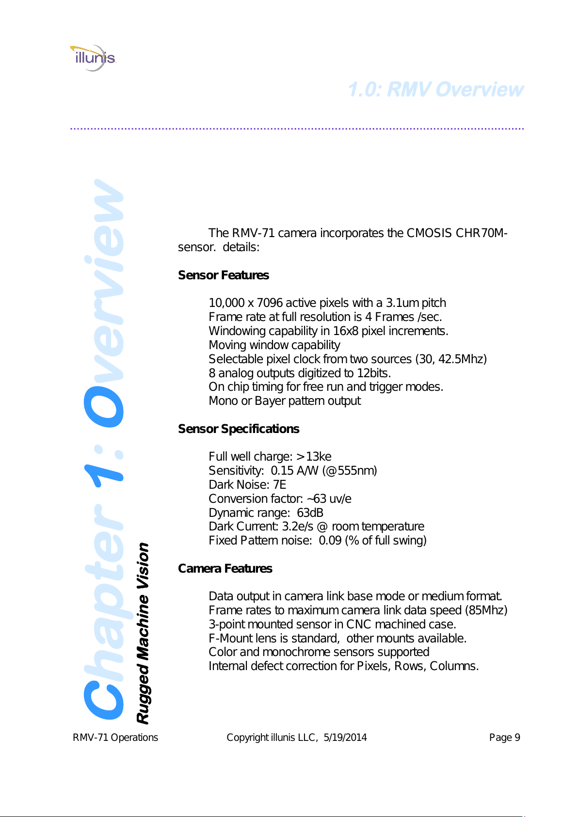
The RMV-71 camera incorporates the CMOSIS CHR70M-
sensor. details:
Sensor Features
10,000 x 7096 active pixels with a 3.1um pitch
Frame rate at full resolution is 4 Frames /sec.
Windowing capability in 16x8 pixel increments.
Moving window capability
Selectable pixel clock from two sources (30, 42.5Mhz)
8 analog outputs digitized to 12bits.
On chip timing for free run and trigger modes.
Mono or Bayer pattern output
Sensor Specifications
Full well charge: > 13ke
Sensitivity: 0.15 A/W (@555nm)
Dark Noise: 7E
Conversion factor: ~63 uv/e
Dynamic range: 63dB
Dark Current: 3.2e/s @ room temperature
Fixed Pattern noise: 0.09 (% of full swing)
Camera Features
Data output in camera link base mode or medium format.
Frame rates to maximum camera link data speed (85Mhz)
3-point mounted sensor in CNC machined case.
F-Mount lens is standard, other mounts available.
Color and monochrome sensors supported
Internal defect correction for Pixels, Rows, Columns.
1.0: RMV Overview
All manuals and user guides at all-guides.com
RMV-71 Operations Copyright illunis LLC, 5/19/2014 Page 10
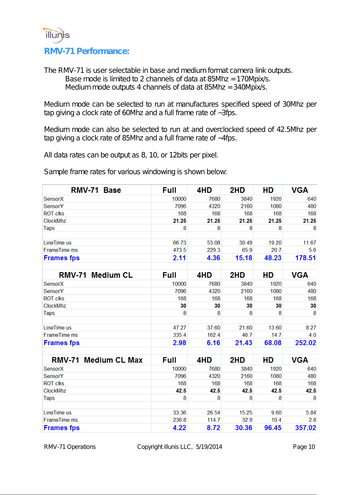
RMV-71 Performance:
The RMV-71 is user selectable in base and medium format camera link outputs.
Base mode is limited to 2 channels of data at 85Mhz = 170Mpix/s.
Medium mode outputs 4 channels of data at 85Mhz = 340Mpix/s.
Medium mode can be selected to run at manufactures specified speed of 30Mhz per
tap giving a clock rate of 60Mhz and a full frame rate of ~3fps.
Medium mode can also be selected to run at and overclocked speed of 42.5Mhz per
tap giving a clock rate of 85Mhz and a full frame rate of ~4fps.
All data rates can be output as 8, 10, or 12bits per pixel.
Sample frame rates for various windowing is shown below:
All manuals and user guides at all-guides.com
RMV-71 Operations Copyright illunis LLC, 5/19/2014 Page 11
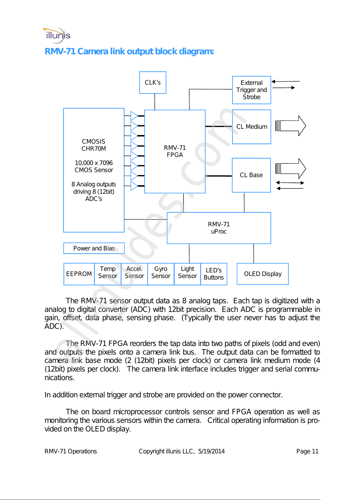
RMV-71 Camera link output block diagram:
CMOSIS
CHR70M
10,000 x 7096
CMOS Sensor
8 Analog outputs
driving 8 (12bit)
ADC’s
RMV-71
FPGA
RMV-71
uProc
CL Medium
Accel.
Sensor
Temp
Sensor
CL Base
Gyro
Sensor Light
Sensor
Power and Bias
External
Trigger and
Strobe
EEPROM OLED Display
LED’s
Buttons
CLK’s
The RMV-71 sensor output data as 8 analog taps. Each tap is digitized with a
analog to digital converter (ADC) with 12bit precision. Each ADC is programmable in
gain, offset, data phase, sensing phase. (Typically the user never has to adjust the
ADC).
The RMV-71 FPGA reorders the tap data into two paths of pixels (odd and even)
and outputs the pixels onto a camera link bus. The output data can be formatted to
camera link base mode (2 (12bit) pixels per clock) or camera link medium mode (4
(12bit) pixels per clock). The camera link interface includes trigger and serial commu-
nications.
In addition external trigger and strobe are provided on the power connector.
The on board microprocessor controls sensor and FPGA operation as well as
monitoring the various sensors within the camera. Critical operating information is pro-
vided on the OLED display.
All manuals and user guides at all-guides.com
all-guides.com

RMV-71 Operations Copyright illunis LLC, 5/19/2014 Page 12
All manuals and user guides at all-guides.com

RMV-71 Operations Copyright illunis LLC, 5/19/2014 Page 13
RMV-71 Specifications:
Item RMV-71
Active Image 10,000 x 7096 (Windowing optional)
Sensor Type CMOSIS CHR70M
Pixel Size 3.1um x 3.1um
Sensor output 8 taps
Video output 8/10/12 bits
Output format Mono or Bayer
Camera Interface Base or Medium format Camera link
Electronic shutter Rolling shutter with Global reset
Max Frame Rate at Full Res. 4 fps (medium CL) 2 fps (base CL)
Pixel Clock 30/40Mhz
Shutter Speed Increments of one line time.
Windowing H increments of 16 columns, V increments of 8 rows
Black Level Adjustable
Analog Gain 1X ~ 40X
Digital Gain 1X-16X (1/4096 step)
Exposure modes Programmed free run, Programmed triggered
External Trigger 3.3-5.0V TTL
Software Trigger Per Camera API
Dynamic Range 63dB
Defect Correction Pixel + Column + Row
Flat Field Correction Column Gain, Tap offset
Lens Mount F-Mount, Canon-EF, Large Format Copal, Custom
Power 6-14V DC, Max 8W
Environmental Operating 0C to 60C, Storage –40C to +85C
Vibration/Shock 10G (20-200Hz) XYZ 70G 10ms
All manuals and user guides at all-guides.com

RMV-71 Operations Copyright illunis LLC, 5/19/2014 Page 14
The RMV-71 camera is completely field upgradable for all firmware using our free
GUI control application. Go to www.illunis.com and click on software.
For more information please call at (952) 975-9203 or email: info@illunis.com
1.1: RMV Overview
Firm Ware Updates
1.2: RMV Overview
Warranty
Warranty. illunis warrants that all products will perform in normal use in ac-
cordance with specifications for a period of one year from date of shipment. This
warranty does not cover failure due to those mechanical and electrical causes de-
fined below as liability of the customer. If the device does not function properly dur-
ing the warranty period, illunis will at it’s option, either repair or replace the unit. In
the case of replacement, illunis reserves the right to re-use the original CCD serial
number if found to be performing to specification. Illunis does not warranty glassless
CCD’s. Please refer to the terms and conditions included with your quotation for full
warrantee information.
Returns. Products will be considered for replacement for up to one year from
the date of shipment. All returns require an RMA number. No returns will be accept-
ed without an RMA number. Returns will be re-tested against the device acceptance
criteria and if found to meet those criteria will be shipped back to the customer at the
customer’s expense.
All returns should be sent to: Illunis LLC
Attn: RMA coordinator
15713 Elodie Lane
Minnetonka, MN 55345
(952) 975-9203
All manuals and user guides at all-guides.com

RMV-71 Operations Copyright illunis LLC, 5/19/2014 Page 15
1.3: RMV Overview
Compliance
The RMV-71 is tested to comply with the following:
Coming Soon !
1.4: RMV Overview
Power Consumption
The RMV-71 can operate in the following modes with estimated power:
Base mode at 20Mhz pixel clock = 4.2W @ 12VDC
Medium mode at 30Mhz pixel clock = 5.2W at 12VDC
Medium mode at 40Mhz pixel clock = 6.2W at 12VDC
All measurements at full readout (10,000x7096)
Note: At lower input voltage the power draw is slightly higher.
All manuals and user guides at all-guides.com
RMV-71 Operations Copyright illunis LLC, 5/19/2014 Page 16
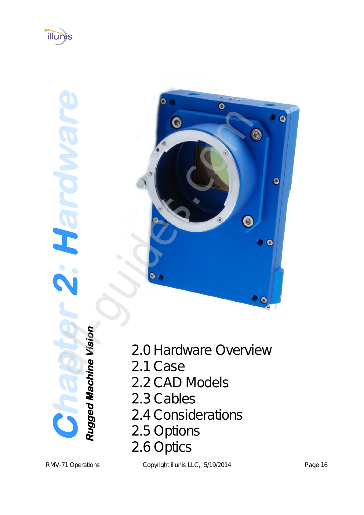
Chapter 2:Hardware
Rugged Machine Vision
2.0 Hardware Overview
2.1 Case
2.2 CAD Models
2.3 Cables
2.4 Considerations
2.5 Options
2.6 Optics
All manuals and user guides at all-guides.com
all-guides.com

RMV-71 Operations Copyright illunis LLC, 5/19/2014 Page 17
2.0: Hardware
Overview
Exploded View showing Lens mount, Optical Filter, Circuit board and assembly screws.
The RMV-71 case is constructed of aircraft grade aluminum and is CNC machined. The lens
mount is designed for Nikon F-Mount lens and can be removed and/or replaced with alternate lens
mounts. The case does not incorporate a fan, however at maximum power the camera will draw ~6W.
The camera incorporates a OLED graphical display as well as LED’s and two buttons for user interac-
tion.
Drawings follow:
Dimensions are in mm [inches]
F-Mount
Ring
Optical Filter for
sealed sensor
chamber
Removable
Lens mount CNC Machined
Case
Status LED’s OLED
Display
(Backside)
Mode
Buttons (2)
3-Point
mounted
Sensor
Features of the RMV-71 camera
All manuals and user guides at all-guides.com

RMV-71 Operations Copyright illunis LLC, 5/19/2014 Page 18
Three View
All manuals and user guides at all-guides.com

RMV-71 Operations Copyright illunis LLC, 5/19/2014 Page 19
Top view Bottom view
OLED Menu
Select Button
Status and
Motion LED’s Mode Select
Button Power
Connector
Camera Link
Base Camera Link
Medium
All manuals and user guides at all-guides.com
RMV-71 Operations Copyright illunis LLC, 5/19/2014 Page 20
CAD Models Detailed Drawings
The RMV case dimensions can be provided as a manufacturing drawings and as a solid model
that can be imported into almost any CAD system. For access to these drawings please contact illunis
at www.illunis.com , Phone (952) 975-9203, or email: info@illunis.com
CAD Models supported are STEP, IGES, ProE native, and many others
2.2: Hardware
CAD Models
HRS
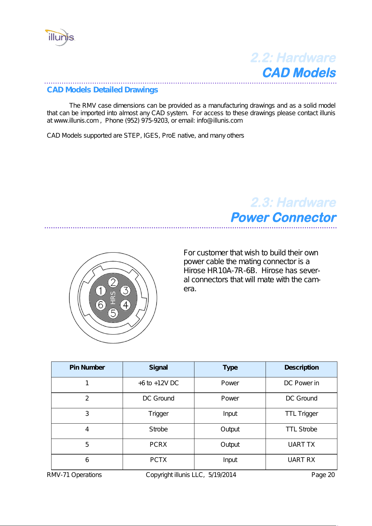
2.3: Hardware
Power Connector
Pin Number Signal Type Description
1 +6 to +12V DC Power DC Power in
2 DC Ground Power DC Ground
3 Trigger Input TTL Trigger
4 Strobe Output TTL Strobe
5 PCRX Output UART TX
6 PCTX Input UART RX
For customer that wish to build their own
power cable the mating connector is a
Hirose HR10A-7R-6B. Hirose has sever-
al connectors that will mate with the cam-
era.
All manuals and user guides at all-guides.com
Table of contents
Other illunis Digital Camera manuals


