illunis EMC-51 User manual

Operations Manual
Advanced Digital Machine Vision Cameras
EMC
Embedded Machine Camera
EMC-51
EMC-65
EMC-103
EMC Operations Manual Copyright illunis, LLC 1/12/2023 Page 2
Revisions
EMC (51, 65, 103)
Rev Date Modification
A01/06/23 Initial Release
Camera Communication Default Baud Rate is 115,200

EMC Operations Manual Copyright illunis, LLC 1/12/2023 Page 3
Introduction
The EMC cameras based on the Gpixel GMAX sensors share a common FPGA and
Microprocessor firmware. The EMC case design is compact and light weight, making it ideal
for Arial and other embedded solutions.
Supported Sensors
• GMAX4651 : 8424x 6032 Global shutter, 3.2um pixel
• GMAX3265: 9344x7000 Global shutter, 3.2um pixel
• GMAX32103: 11,276x9200 Global shutter, 3.2um pixel
Supported Outputs
• Camera Link
• Epix mf2280 (Samtec HLCD)
• Pleora GigE
• Pleora USB3
• Pleora NTX-DECA (10G ethernet)
Note: All Output types may not be available for larger sensors.
Supported Lens Mounts
• Canon EF
• F-Mount
• M42
• M58
• OEM
Common features include:
Global Electronic Shutter
Horizontal and Vertical image flip
Vertical Subsampling and ROI
External triggering
12bit ADC with analog gain
Optical black clamp in FPGA
Low noise with excellent PLS
There are differences in the features of the supported sensors
GMAX4651 does not support VFlip
GMAX3265 does support dual exposure HDR mode

EMC Operations Manual Copyright illunis, LLC 1/12/2023 Page 4
Precautions
EMC (51, 65, 103)
EMC Precautions
Do not drop, damage, disassemble, immerse, repair or alter the
camera.
Applying incorrect power may damage the camera electronics.
The warranty is void if the camera is opened or modified in any
way.
Care must be taken in handling as not to create static dis-
charge that may permanently damage the device.
Camera Link is a DC based interface. The camera and capture
device must share the same electrical ground. Failure to do so
will damage the Camera Link interface chips and/or camera
and capture card.
PoCL cables are compatible with EMC Camera Link
cameras. PoCL camera power is not supported.
Absolute Maximum Ratings
Input Voltage: 7 to 14V DC
Storage Temperature: -40C to +70C
Recommended Maximum Ratings
Input Voltage: 7 to 14V DC
Operating Temperature: 0C to +70C
Most illunis cameras operate beyond these temperature limits,
please call for details.
Recommended Operating Conditions
Input Voltage: 9-12V DC
Operating Temperature: 0C to +70C
Relative humidity should not exceed 80% non-condensing.
Specifications subject to change without notice.

EMC Operations Manual Copyright illunis, LLC 1/12/2023 Page 5
Contents
EMC (51, 65, 103)
Table of Contents Page
Getting Started - Epix 6
Getting Started - GigE/USB3 7
Getting Started - Camera Link 8
Getting Started - Camera Link Serial 10
Getting Started - Camera Control App 14
Getting Started - Epix XCAP 23
Getting Started - Teledyne Dalsa Cam Expert 25
Camera Overview EMC-51 27
Camera Overview EMC-65 32
Camera Overview EMC-103 37
Hardware Overview 43
Serial Communication 48
Serial Commands 51
Gain and Black Level 53
Fast Meter and AE 56
Digital On Screen Display (DOSD) 57
Auto Exposure PBM 59
Command Details 62
Firmware Loader 66
Pixel, Row and Column Defects 68
Hot Pixel Correction 69
Shading Correction 71
Image Storage and Display 77
Camera Drawings 80

EMC Operations Manual Copyright illunis, LLC 1/12/2023 Page 6
Camera Power Epix
6-12V DC Power to the JST ZHR-7 connector.
View from Camera Back
Capture Card
Epix PIXCI® mf2280+
Imaging SDK
XCLIB™ Frame Grabber Programming Library (epixinc.com)
Camera Communication Software
illunis Camera Control Application Help Center – illunis
Data Cable
COTS Samtec HLCD
HLCD-20-XX-00-TR-TR-1 (XX = length in inches)
Digi-Key (other lengths available)
Getting Started Epix
EMC (51, 65, 103)
Power
7- Power
6- GND
5- Trigger In (LVTTL)
4- Strobe out (LVTTL)
3- GND
2- Power
1- Shell
EMC Operations Manual Copyright illunis, LLC 1/12/2023 Page 7
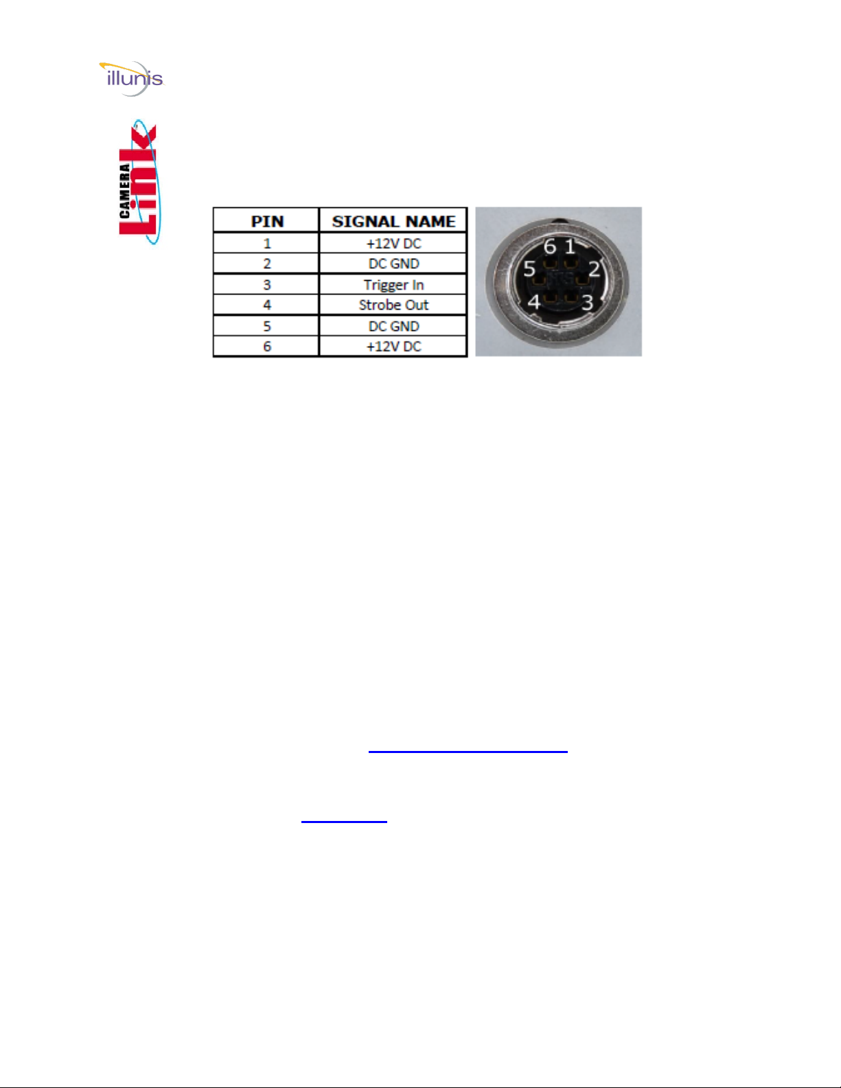
Camera Power GigE/USB3
6-12V DC Power to the Hirose 6 pin connector.
Mating Connector: Hirose HR10A-7P-6P
View from Camera Back
Capture Card
1 Gbps ethernet connection or compatible USB3 port.
Imaging SDK
Pleora SDK Pleora.com
Camera Communication Software
illunis Camera Control Application
Download at: Help Center – illunis
Getting Started GigE/USB3
EMC (51, 65, 103)
EMC Operations Manual Copyright illunis, LLC 1/12/2023 Page 8
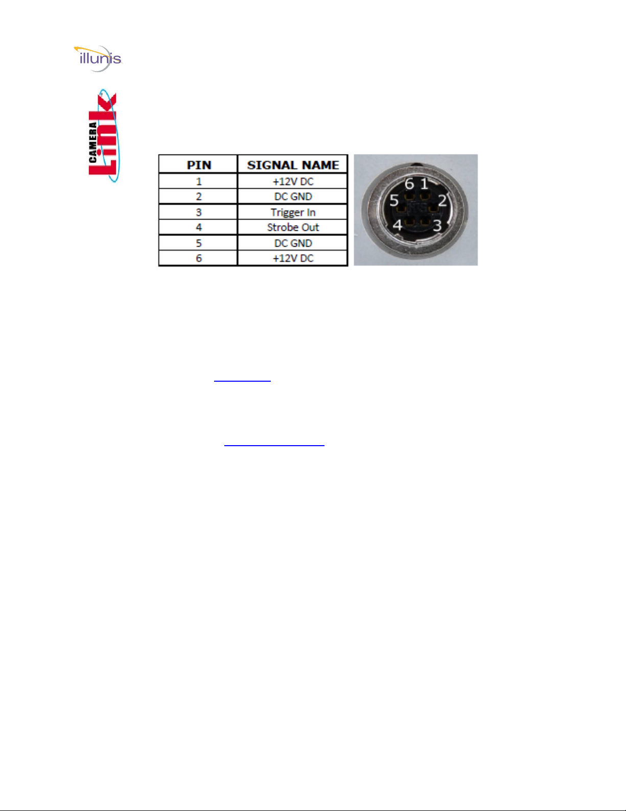
Camera Power Camera Link
6-12V DC Power to the Hirose 6 pin connector.
Mating Connector: Hirose HR10A-7P-6P
View from Camera Back
Camera Power Pins 5 and 6 can be left unconnected for the fan cooled
version of the camera.
Capture Card
Any Base, Medium or Full Format Camera Link capture card
Such as: Teledyne Dalsa Xtium-CL MX4 OR-Y4CO-XMX00.
Imaging SDK
Available from your capture card supplier.
Camera Link Cables
One or two Camera Link cables (Mini HDR to SDR) must be
rated at 85Mhz or more (two cables for Medium or Full Format).
The following 5M cable configurations have been tested:
Standard MDR to HDR/SDR MVC-1-1-5-5M
Available from Components Express.
componentsexpress.com
Camera Communication Software
illunis Camera Control Application
Download at: illunis.com
Getting Started Camera Link
EMC (51, 65, 103)

EMC Operations Manual Copyright illunis, LLC 1/12/2023 Page 9
To start imaging with the EMC–CL:
Install the capture card and software per the capture card
manufacturers instructions.
Connect the EMC Camera Link cables paying attention to
the base and medium connections
Getting Started Camera Link
EMC (51, 65, 103)
Camera Link Medium mode setup
Blue cable = Base Mode Connection
Green cable = Medium/Full and Deca
Connection
Camera Link
Communication: CLA
A
Cable Connections for Camera Link Medium/Full and Deca
Mode Operation.
Base Mode uses only CLA Base Connection
EMC Operations Manual Copyright illunis, LLC 1/12/2023 Page 10
Camera Link Serial Overview
Download and install the illunis Camera Serial
Communication Software from
https://www.illunis.com
Background:
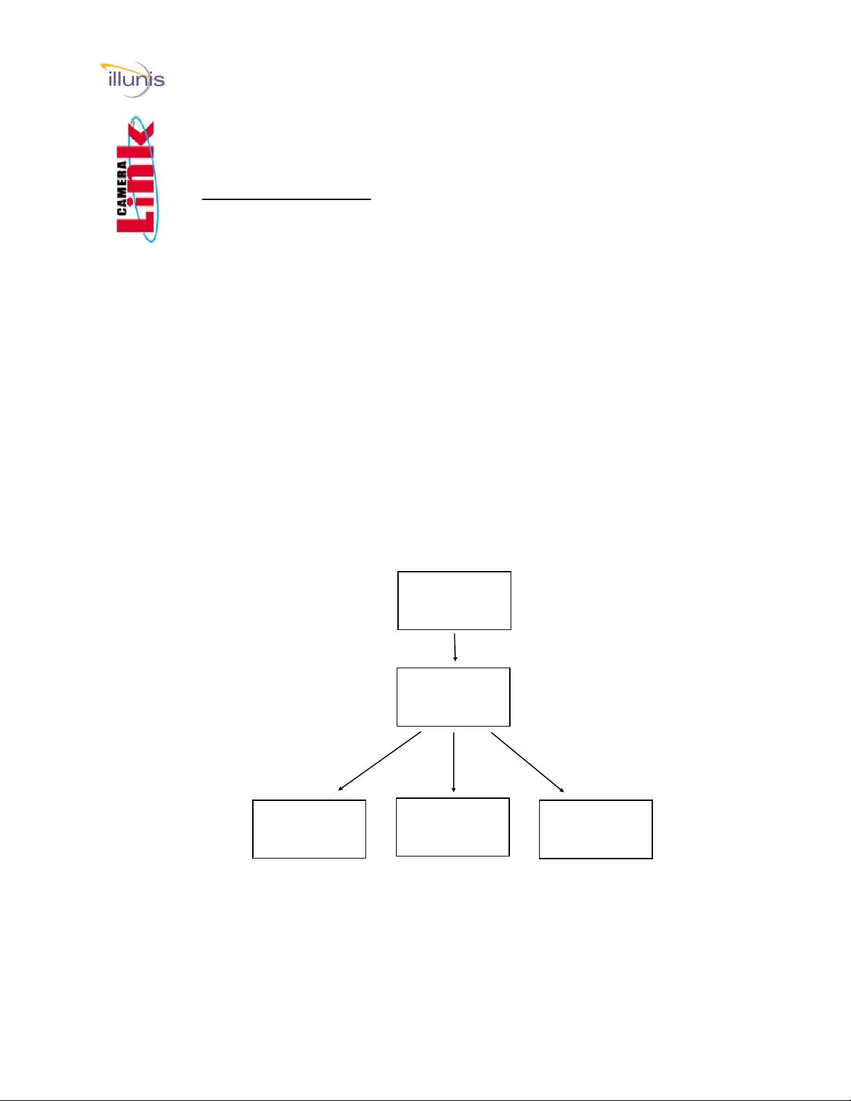
Per the CameraLink standard, all serial communication is via the .dll
clallserial.dll, which dynamically loads the serial communication .dll(s)
specific to the frame grabber being used. illunis installs clallserial.dll in
its application directory.
clallserial.dll examines the registry to see where the capture card
specific communication dll's have been installed. The naming
convention for the capture card specific communication dll's is
clser***.dll where *** is the manufacturer specific dll name. The files
MUST be in the form clser***.dll in order to be recognized. Some
capture card manufacturers will append something like clser***x64.dll
for the 64 bit version of the .dll. This file name must be changed to
clser***.dll in order to be recognized by clallserial.dll.
illunis camera
control app
clallserial.dll
clserxxx.dll clseryyy.dll clserzzz.dll
Getting Started Camera Link Serial
EMC (51, 65, 103)
EMC Operations Manual Copyright illunis, LLC 1/12/2023 Page 11
Camera Link Serial Epix
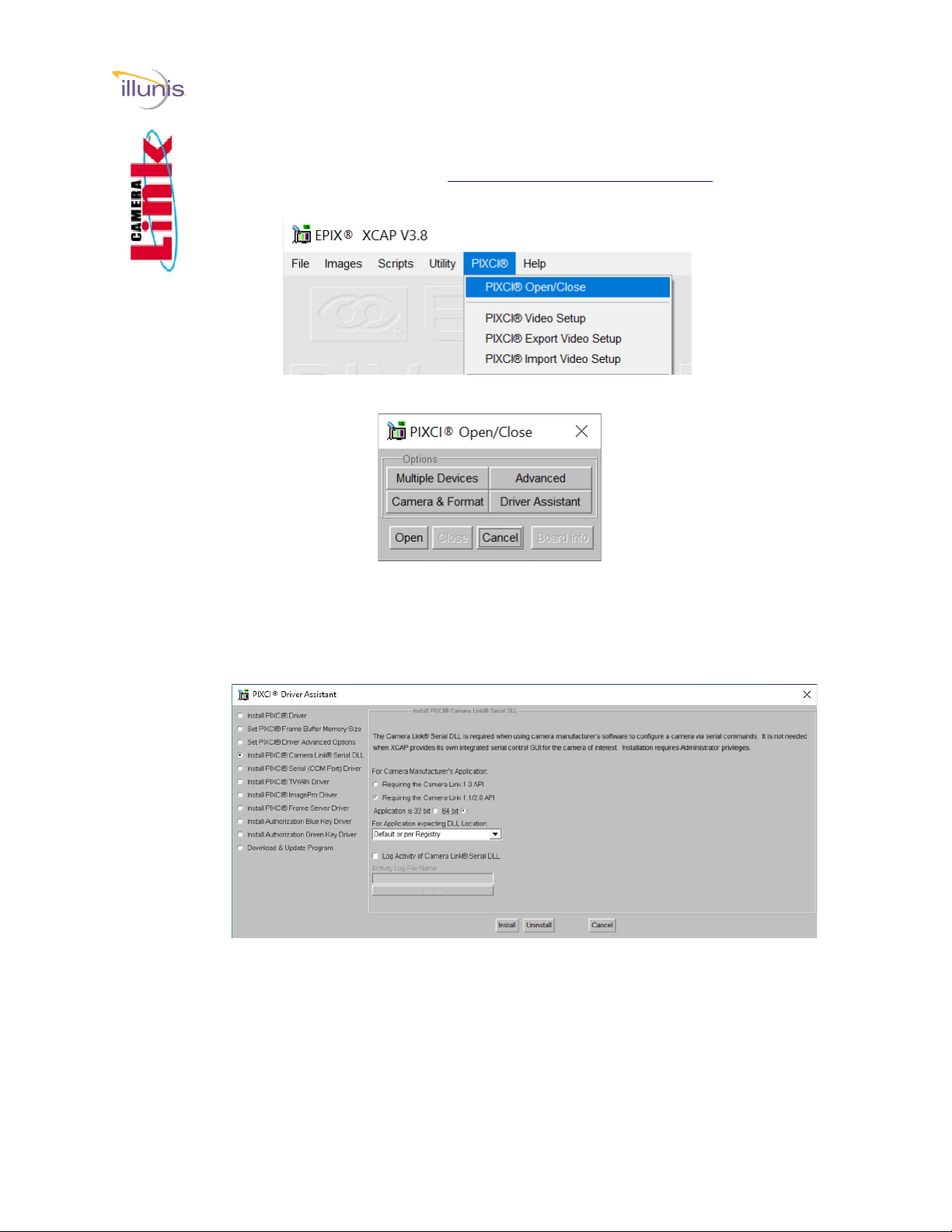
1. Install and open XCAP EPIX® Software Download (epixinc.com)
2. From the menu choose PIXCI -> PIXCI Open/Close
3. Close the capture card if open, then click “Driver Assistant”.
4. Choose “Install PIXCI Camera Link Serial DLL
• Choose Camera Link 1.2/2.0 API
• 64 bit
5. Then “Install”
Note: Epix Camera Link dll is names clserEPX.dll
Getting Started Camera Link Serial
EMC (51, 65, 103)

EMC Operations Manual Copyright illunis, LLC 1/12/2023 Page 12
Camera Link Serial Pleora (GigE/USB3)
1. Download and install Pleora eBUS Player or eBUS SDK. eBUS SDK
and eBUS Player (pleora.com)
2. The Camera Link serial dll will be installed in C:\Program
Files\Common Files\Pleora\eBUS SDK\ by default
3. To use the 64-bit dll, it will need to be renamed from
clserpte_w64.dll to clserpte.dll (the 32-bit dll can be deleted or
renamed to preserve it).
Getting Started Camera Link Serial
EMC (51, 65, 103)
EMC Operations Manual Copyright illunis, LLC 1/12/2023 Page 13
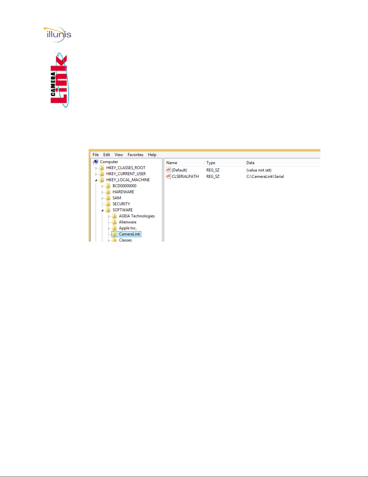
The registry:
When clallserial.dll is loaded by the illunis serial communication application, it
looks at the Registry entry:
HKEY_LOCAL_MACHINE\SOFTWARE\Cameralink CLSERIALPATH.
The location pointed to by CLSERIALPATH is typically C:\Cameralink\Serial,
but could be any path that a capture card install might create. It is important to
note that the capture card communication dll(s), clser***.dll must be at this
path location. clallserial.dll should NOT be in this location.
If the capture card communication dll is spec 1.1 compliant, the user will find
this directory already created.
The illunis control app installs clallserial.dll for the appropriate operating
system in the application folder. Depending on the application version, some
documentation may be installed in the application folder as well.
If the registry entry above does not exist, create it as well as the directory
C:\CameraLink\Serial
In either case—copy and paste the clser***.dll files to the
C:\CameraLink\Serial folder.
Getting Started Control App
EMC (51, 65, 103)

EMC Operations Manual Copyright illunis, LLC 1/12/2023 Page 14
Installing prerequisite software:
The status of these items can be checked in the Control Panel ->
Programs and Features listing. If necessary download and install the
following prerequisites.
1. .NET Framework 4.6.1 to be installed from:
https://www.microsoft.com/en-us/download/details.aspx?id=49981
2. Visual C++ 2010 Redistributable from:
https://www.microsoft.com/en-us/download/details.aspx?id=14632
3. Visual C++ 2013 Redistributable from:
https://www.microsoft.com/en-us/download/details.aspx?id=40784
Getting Started Control App
EMC (51, 65, 103)
EMC Operations Manual Copyright illunis, LLC 1/12/2023 Page 15
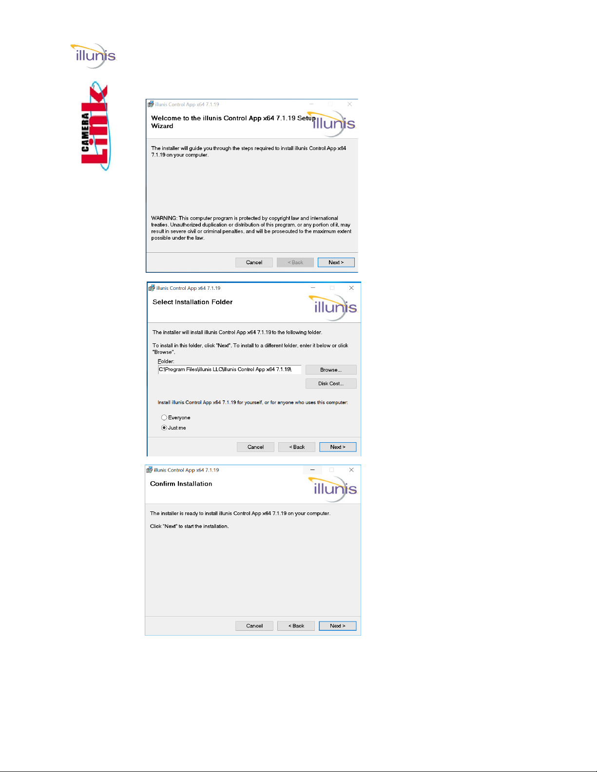
Install the Camera Serial Communication Software:
Launch the installer
Select the installation
folder...
Confirm...
Getting Started Control App
EMC (51, 65, 103)

EMC Operations Manual Copyright illunis, LLC 1/12/2023 Page 16
Install complete…
Note: A shortcut to the
program will be placed on
the desktop.
Power up the camera and run the illunis Camera Serial
Communication Software.
If there are multiple clserxxx.dll’s for multiple cards installed, a choice of
possible connections will be presented.
If there is only a single capture board present and one clserxxx.dll, the
application will simply connect to that card/port.
Getting Started Control App
EMC (51, 65, 103)
EMC Operations Manual Copyright illunis, LLC 1/12/2023 Page 17
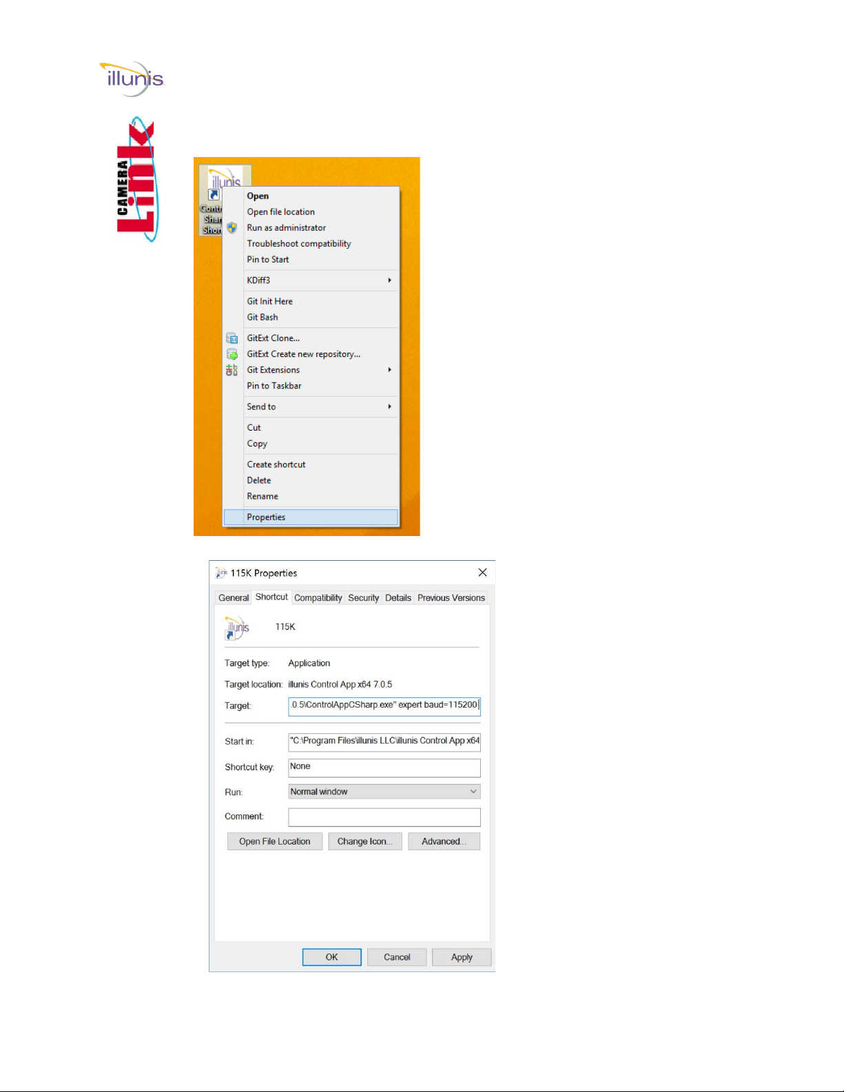
Disabled Menus
By default, sensitive menu
items are disabled to pre-
vent inadvertent changes to
the camera state. To enable
them, a new shortcut has to
be created on the desktop.
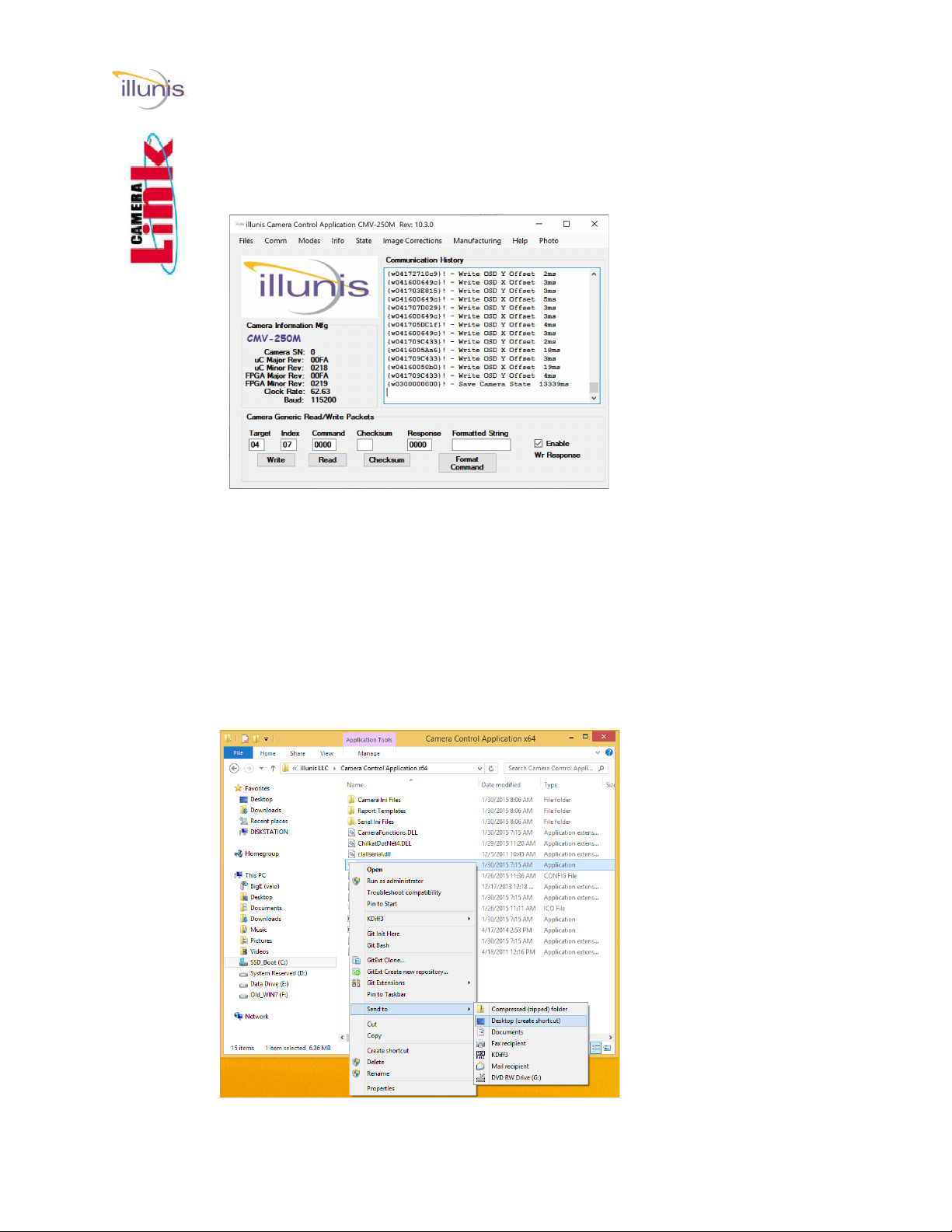
First, delete the desktop
shortcut created by the
installer.
Create a new Shortcut
Navigate to the program
install directory and right
click on the file with the
illunis icon and exten-
sion .exe. Choose ->
Send to -> Desktop. This
creates a new desktop
shortcut icon.
illunis Camera Serial Communication Software Main Window:
Creating a new shortcut for program options:
Getting Started Control App
EMC (51, 65, 103)
EMC Operations Manual Copyright illunis, LLC 1/12/2023 Page 18
Right click on the newly created desktop
icon and select Properties.
Add a space and the words
expert baud=115200 after
the close quote on the
Target: line of the dialog
box: .exe” expert
Choose OK.
When the program is
launched, all menus will be
enabled.
NOTE: Starting with ver-
sion 10.x baud=115200 is
no longer required, the
app will try all baud rates
on connection
NOTE: Use care with all
menus enabled as some
changes cannot be un-
done and may require the
camera be returned to the
factory for remedy.
Adding options to the shortcut command line:
Getting Started Control App
EMC (51, 65, 103)
EMC Operations Manual Copyright illunis, LLC 1/12/2023 Page 19
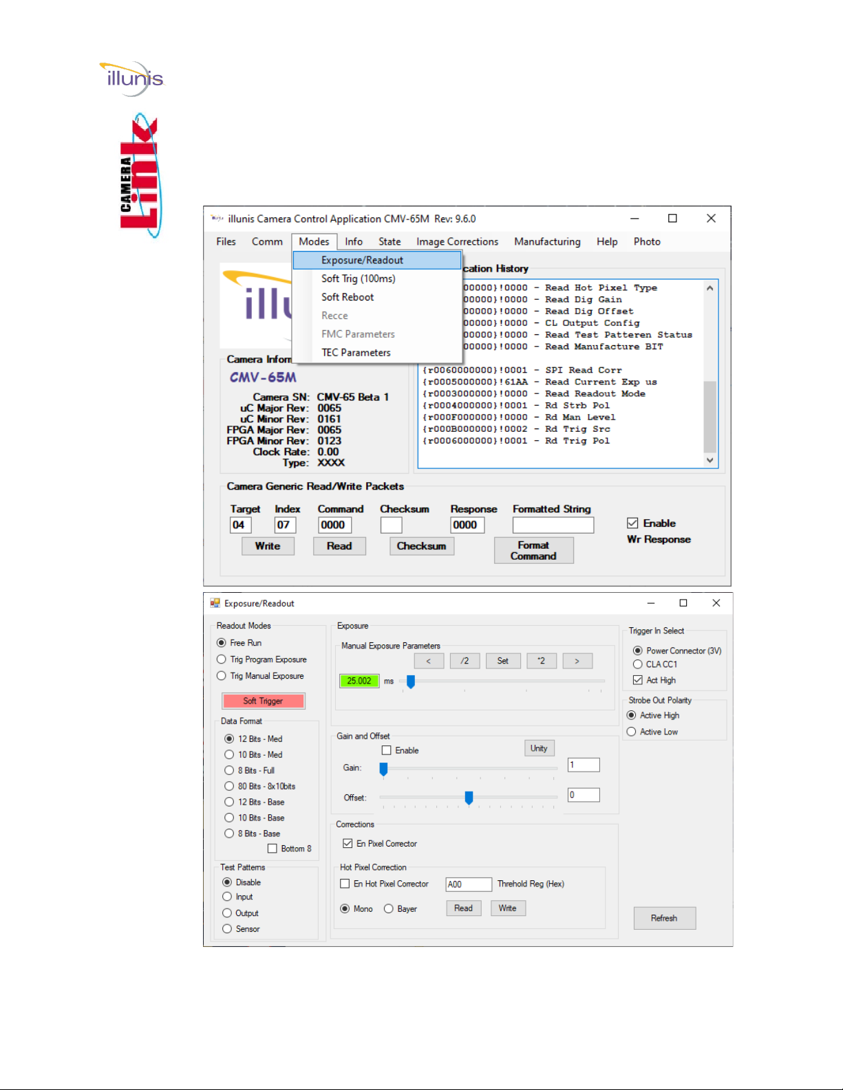
Exposure / Readout:
Start with this dialog box as most of the immediately useful controls are located here.
Getting Started Control App
EMC (51, 65, 103)

EMC Operations Manual Copyright illunis, LLC 1/12/2023 Page 20
Camera Control Application Details:
Getting Started Control App
EMC (51, 65, 103)
Main Dialog
The main dialog box provides access to the
various functions of the camera. Menus
are used to access sub-dialogs. A generic
camera register read/write feature is
provided.
In addition, a history of communication is
also provided in this dialog box.
Modes->Exposure and Readout
This dialog box is used to set the Readout
Mode, Free Run, or Trigger, as well as the
bit depth and exposure of the camera. In
addition, the user can set the Camera Link
mode, test patterns, digital gain and offset,
and histogram equalization.
This manual suits for next models
2
Table of contents
Other illunis Digital Camera manuals


