Imesa M8-RC8 Parts list manual

E190601X rev.6_ENG May 30, 2022
1
WASHING MACHINES
INSTRUCTIONS FOR
INSTALLATION
USE AND
MAINTENANCE
KEEP FOR FUTURE REFERENCE
IMESA S.p.A.
Via degli Olmi 22
31040 Cessalto (TV) - Itali
ITALY

E190601X rev.6_ENG May 30, 2022
2
Summary
1. CONTENT OF THE MANUAL ............................................................................................................................................. 3
2. SAFETY RULES .................................................................................................................................................................... 3
3. RESPONSIBILITY OF THE MANUFACTURER................................................................................................................. 6
4. STORAGE AND UNPACKING ............................................................................................................................................. 6
5. INSTALLATION AND PLACEMENT .................................................................................................................................. 8
6. MACHINE IDENTIFICATION .............................................................................................................................................. 9
7. INDICATIONS ON NOISE EMISSION ................................................................................................................................ 9
8. FIXING TO THE GROUND................................................................................................................................................... 9
9. ELECTRICAL CONNECTION ............................................................................................................................................ 11
10. HYDRAULIC CONNECTION: WATER LOAD ................................................................................................................ 15
11. HYDRAULIC CONNECTION: WATER DRAIN .............................................................................................................. 16
12. STEAM CONNECTION.................................................................................................................................................... 16
13. COMPRESSED AIR CONNECTION ............................................................................................................................... 18
14. USE OF DETERGENTS.................................................................................................................................................... 18
15. MACHINE START-UP AND TESTING........................................................................................................................... 18
17. PREPARING CHAPTERS ................................................................................................................................................ 21
18. LOAD THE MACHINE AND CLOSE THE DOOR' ......................................................................................................... 22
19. MANUAL OPENING OF THE DOOR' ............................................................................................................................. 22
20. TURNING ON THE MACHINE........................................................................................................................................ 26
21. SELECTION OF A PROGRAM ........................................................................................................................................ 26
22. FAVORITE PROGRAMS .................................................................................................................................................. 27
23. LATE START ..................................................................................................................................................................... 27
24. IMPLEMENTATION OF A PROGRAMME..................................................................................................................... 28
25. PAUSE OF A PROGRAM ................................................................................................................................................. 28
26. FAST FORWARD.............................................................................................................................................................. 29
27. END OF IMPLEMENTATION OF A PROGRAMME ..................................................................................................... 29
28. END OF WORKING DAY ................................................................................................................................................. 30
29. PROGRAMMING .............................................................................................................................................................. 30
30. DISPLAY REPORTS ......................................................................................................................................................... 30
31. PROGRAMS IN MEMORY .............................................................................................................................................. 33
32. OTHER FUNCTIONS ....................................................................................................................................................... 33
33. MAINTENANCE OF THE WASHING MACHINE.......................................................................................................... 33
34. WASHING PROBLEMS ................................................................................................................................................... 34
35. USE OF THE TILTING MACHINE .................................................................................................................................. 35
36. EASY DOWNLOAD........................................................................................................................................................... 36
37. PROCEDURE FOR CHECKING SAFETY DEVICES ..................................................................................................... 36
38. SCRAPPING...................................................................................................................................................................... 37
39. WARRANTY CONDITIONS ............................................................................................................................................. 37

E190601X rev.6_ENG May 30, 2022
1. CONTENT OF THE MANUAL
This manual is dedicated to the use of industrial washing machines. It shall be drawn up in the consideration of
the Community directives in force. The information is addressed to the installer and the user, who must be sure
to have fully understood it before operating on the machine. The user manual must always be available for
consultation. In case of loss or damage, ask the manufacturer for a new manual. The manufacturer is not liable
for the consequences deriving from a careless use of the machine due to a failure or incomplete reading of this
manual. The manufacturer reserves the right to modify the specifications mentioned in this manual or the
characteristics of each machine. Some figures in this manual may show details that are partially different from
those assembled on the machines. Drawings and technical data may be modified without notice.
The manual and its annexes are an integral part of the apparatus; therefore, they must be kept and accompany
the apparatus, even in the case of transfer to another utilizer.
The same attachments and the exploded with the related spare parts can be found in the technical area of the
manufacturer's website. Before accessing the site, it is essential to have the serial number of the machine
available.
ATTENTION!
The manufacturer declines all responsibility for possible inaccuracies contained in this manual due to printing
or transcription errors. It reserves the right to make any changes to its products as it deems necessary or useful,
without prejudice to its essential characteristics. It is forbidden to reproduce, even partially, texts or images of
this manual, without the prior authorization of the manufacturer.
2. SAFETY REGULATIONS
ATTENTION!
Failure to comply with the following safety regulations may cause damage to people, property and animals.
ATTENTION!
The installation and maintenance of the machines described in this manual must be done by authorized
personnel who know the product and comply with European industry standards.
Incorrect repairs can seriously endanger the user's safety.
ATTENTION!
Before starting the machine, read these instructions carefully: make the instructions accessible to all persons in
charge of using the washing machine.
ATTENTION!
The intended use of the washing machines described here is the professional washing of clothing and water
linen: any other intended use is therefore prohibited unless it has been previously authorized in writing by the
manufacturer. Never use dry cleaning products.
ATTENTION!
It is for bidden to wash garments that are soaked in substances manifestly harmful to the health of operators,
poisons, or carcinogenic products.
ATTENTION!
Do not approach the machine with combustible or flammable products to avoid the risk of fire and explosion.

E190601X rev.6_ENG May 30, 2022
4
ATTENTION!
Always follow the washing instructions on each item of linen with great care.
ATTENTION!
It is forbidden to use the machine to children under the age of 16.
ATTENTION!
Additional connections to the machine from the outside, not carried out in a workmanlike manner, relieve the
manufacturer of any responsibility.
ATTENTION!
Do not spray or wash the machine with water.
ATTENTION!
Do not exclude the porthole locking device.
ATTENTION!
Do not let children play with or inside the washing machine. Children should be kept under close surveillance,
when close to the washing machine.
ATTENTION!
Machines with heating systems imply a potential risk of fire. All precautions related to this risk must therefore
be taken: the environment must be free from combustible materials; provide for an adequate and easily
accessible fire extinguisher near the machine.
ATTENTION!
It is forbidden to work with the shelters of open machines! Danger of crushing.
ATTENTION!
In order to avoid sunburn or crushing of the limbs, it is absolutely forbidden to remove, even temporarily, the
protection panels and security systems!
ATTENTION!
It is forbidden to introduce bars, slats or metal objects inside the basket. In the event of an emergency, always
perform the following procedures:
ATTENTION!

E190601X rev.6_ENG May 30, 2022
5
Always check the correct functioning of the safety devices every time the machine is started!
It is obligatory to register the operation of the machine and its emergency systems!
DANGER OF BURNS
The machine, by the very nature of the activity for which it is intended, presents the danger of burns.
Any burns can be caused:
-From prolonged contact with the porthole during the execution of a high temperature wash.
-From contact with the components that convey the steam
The following plates have been affixed to the machine, in case of damage to them, the user must replace them
with identical ones.
The machine must always and only be used by properly trained personnel and in the presence of at least one
other operator!
CAREFULLY READ AND INFORM ALL OPERATORS ABOUT INTERVENTION SYSTEMS IN CASE OFSUDDEN
POWER FAILURE
DANGER OF ELECTROCUTION
Any intervention on the electrical parts of the machine must be carried out only by qualified personnel and after
removing the power supply to the machine.
The power and control circuits can only be tampered with by the manufacturer’s staff, under penalty of forfeiture
of the warranty conditions.
On the electrical panel there is the following monitor plate which must be replaced with an identical one if it has
been damaged or removed.
It should be noted that, with reference to electrical hazards, the machine has been designed in accordance with
the regulations and described in the certificate of conformity delivered with the machine.
CPSYCHOPHYSICAL ODES OF THE OPERATOR
The operator in charge of the machine must be in perfect psychophysical condition; during the work the vertical
posture in front of the machine must be assumed. Abrupt movements or uncontrolled gestures must be avoided,
for example during the removal and insertion of the fabrics to be washed to avoid dangerous collisions with the
machine frame.
If other operators or other personnel are present, these must not be a source of distraction for the operator in
charge of the machine.
During the use of the machine, the operator must not be distracted by televisions, radios, etc. nor be subject to
any other source of distraction.
The apparatus is not intended for use by persons whose physical or mental capacities are reduced, or with a
lack of experience or knowledge.
VERY HOT
MATERIALS

E190601X rev.6_ENG May 30, 2022
6
LIGHTING!
In the room where the machine is installed, there must be uniform illumination of intensity 300-500 lux, annoying
glare must also be avoided.
ATTENTION!
These warnings do not cover all possible risks. The user must therefore proceed with the utmost caution in
compliance with the rules.
3. RESPONSIBILITY OF THE MANUFACTURER
The instructions in this manual do not replace but supplement the obligations for compliance with current
legislation on safety and accident prevention standards. With reference to what is reported in this manual, the
manufacturer declines all responsibility in the event of:
- use of the machine contrary to the laws in force on safety and accident prevention.
- incorrect installation of the machine.
- lack of periodic and scheduled maintenance
- failure or incorrect observance of the instructions provided in the manual.
- defects in voltage and mains supply.
- unauthorized modifications to the machine.
- use of the machine by unauthorized personnel.
4. TRANSPORT, STORAGE AND UNPACKING
The machinery must be transported and stored in rooms where temperature and humidity do not exceed the
following values:
- TEMPERATURE: -10°C / +50°C.
- RELATIVE HUMIDITY: max 90% without condensation.
The storage of the machine in environments and methods different from those indicated above can compromise
the electronic components contained within it.
It is recommended to check the machine upon receipt, taking care to report to the carrier any damage caused
during transport, both to the internal components and to the external bodywork.
The machine must be completely unpacked near the place of installation.
The packaging materials must not be dispersed in the environment and must be stored in the appropriate
collection spaces according to current regulations.
Remove the fixing bolts to the pallet with a wrench.
ATTENTION!
Check on the technical sheet, attached to the machine documentation, the net and gross weight: check the
compatibility with the available lifting equipment.
ATTENTION!
The pallet should not be used as a normal machine holder! The machine must always be taken off the pallet and
positioned as described in the relevant paragraph.
ATTENTION!
The machine must be moved only when it is fixed to its pallet: the handling through the forklift must be carried

E190601X rev.6_ENG May 30, 2022
7
out only by qualified and competent personnel.
The super centrifugation machines during transport are locked inside them (the cradle at the base) with stops,
to avoid the stress of the shock absorbers.
ATTENTION!
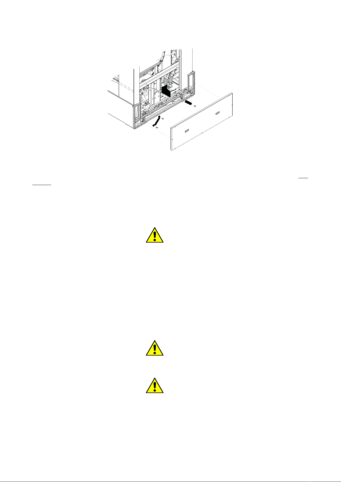
The latches must be removed, after the machine has been placed at and before it is fed.
To disassemble the latches, perform the procedure described below, referring to the figure. The figures are
indicative of the type of stops and not of the machine.
- remove the back and front rings
- unscrew the bolts that block the transport stops
- dismantle transport stops
- reassemble the panels in the original position
For "tilting" machines operate as described below:
Remove the back panel and the lower backrest, proceed to the removal of the transport stops.
E190601X rev.6_ENG May 30, 2022
8
Remove the side panel and the side and proceed to remove the latches.
All panels must be reassembled in the original position before the machine can be started. After removing them,
the retainers must be stored and reused whenever the machinery is to be transported. Transport stops are not
present in rigid washer-washing machines.
5. INSTALLATION AND POSITIONING
All positioning and installation operations must be performed by professionally qualified personnel and
according to the instructions in the relevant installation manual.
ATTENTION!
If the machine cannot be installed respecting the criteria below, it is necessary to request the appropriate
transformations from the manufacturer.
Please note that for proper use, operation, and maintenance, you must leave a free space of at least 600 mm
around the machine. For battery machines, for example in self-service installations, the necessary side space
can be reduced to 10mm.
The ambient temperature must be between +5°C and +40°C.
The smooth operation of the machinery is guaranteed in environments where the residual humidity is not higher
than 50% at a temperature of +40 ° C.
The environment in which the machinery is installed must have sufficient air exchange.
The machinery may not be installed at altitudes above 1000 m above sea level.
The degree of protection is IP24.
ATTENTION!
Do not use or store gasoline, petroleum or other flammable materials in the vicinity of the car. It could cause
fires or explosions.
ATTENTION!
In the case of tilting machines there are external elements of the machine itself, moving during the loading and
unloading phases of the linen.
For the dimensions of the machine and the moving elements in the different positions, refer to the technical
sheet.

E190601X rev.6_ENG May 30, 2022
9
6. MACHINE IDENTIFICATION
The equipment is identifiable by an adhesive plate bearing the serial number, model, power, and technical
characteristics: it is positioned on the back.
Make sure that the power supplies present (electrical, hydraulic, steam, compressed air) correspond to the
license plate data.
Spare parts and / or interventions presuppose the exact identification of the model for which they are intended.
Tampering, removal, lack of identification plates or anything else that does not allow the safe identification of
the machine, makes any installation and maintenance operation difficult and automatically voids the warranty.
The washing machines described here are intended exclusively for water washing of fabrics and are intended
for commercial, professional and industrial sectors.
MODELS AND MAXIMUM LOAD CAPACITY
MODELS AND MAX LOAD CAPACITY
SUPERCENTREFUGEES / HIGH SPIN: S...
CENTRIFUGES / LOW SPIN: R...
TANDEM: O...
ASEPTIC / ASEPTIC BARRIER: H...
CAPACITA'
DI CARICO
/ LOAD
CAPACITY
(Kg)
S8 –R8
8 Kg (*)
S11 –R11 –O11
11 Kg (*)
S14 –R14
14 Kg (*)
S18 –R18 –O18
18 Kg (*)
H18
18 Kg
S23 –R23
23 Kg (*)
H 23
23 Kg
S26
26 Kg (*)
R30
30 Kg
H30
30 Kg
S32
32 Kg
S40 –R40
40 Kg
S55 –R55 -
55 Kg
H55
55 Kg
S70 –R70
70 Kg
S85 –R85
85 Kg
S100
100 Kg
S125
125 Kg
Models with capacities marked with (*) can be produced and equipped for installation in self-service stores
with coin, token or other automatic payment systems. For some machines the heating system is hot water
served.
7. INDICATIONS ON SOUND EMISSION
The airborne noise produced by the machine produces an A-weighted continuous sound pressure level of less
than 72 dB.
8. FIXING TO THE GROUND
Suspended super-fire-aging machines with a capacity of up to 32 kg does not need to be fixed to the ground.
They are supplied with rubber feet that must be screwed to the relative threaded holes on the base.
Poor adjustment of such feet can give rise to strong vibrations of the external structures of the machine. The
machine must therefore be perfectly installed in a bubble on a floor that has no elastic reaction.
Suspended super centrifuge machines with capacities from 30 kg upwards, must instead be fixed to the ground
with dowels through the through holes in the bases. Machines must be installed perfectly in a bubble on a floor that
has no elastic reaction.

E190601X rev.6_ENG May 30, 2022
10
ATTENTION!
It is forbidden to interpose elastic materials of any nature or size between the base of the machine and the floor.
ATTENTION!
Do not install the washing machine on the floors without verification by a competent technician who can assess
the impact of the dynamic load on the floor andbuilding.
In these installations the manufacturer declines all responsibility for possible damage caused by vibrations.
Rigid washer-dryers must all be fixed to the ground.
Rigid machines with capacities from 30kg and above, are supplied with a steel subframe.
- the subframe must be drowned in a concrete basement properly anchored to the floor.
- before anchoring the machine to the basement make sure that the concrete has taken hold and, very
importantly, that the subframe is perfectly bubbled.
- place the machine in the appropriate anchor holes and tighten all the coupling bolts well.
From the attached technical sheet, the measures of the counterframe and the concrete base can be noted.
Land rigid machines with a capacity of up to 23kg are delivered with the equipment of anchors.
Steel anchor
The equipment necessary for installation are:
- Percussion drill or electropneumatic dowel.
- Martello.
- Pomp for cleaning.
- Pipe cleaner.
- Key dynamometer.
Follow the steps below:
- Pprepare a concrete base suitably anchored to the floor, according to the minimum dimensions shown in the
technical sheet.
- To make sure that the concrete base is anchored to the floor, that it has taken hold and that the surface made
is perfectly bubbled.
- To get the machine off the pallet and place it in its final position above the concrete base.
- Through the open panels mark on the concrete base the points where the steel anchors must be positioned,
corresponding to the holes in the metal base of the washing machine.
- Spot the machine to clear the drilling areas.
- And follow the drilling (see-figure) at the points previously identified and based on the technical data
contained in the following table.

E190601X rev.6_ENG May 30, 2022
11
Lt
Anchor length
138
Mm
S
fixable object
thickness
25
Mm
Øf
tip diameter
18
Mm
P
minimum hole depth
140
Mm
Hv
minimum anchorage
depth
80
Mm
Ch
Key
19
-
M
Tightening torque
80
Nm
-
thread
M12
-
- And to extract the concrete residues with a brush from the hole just made and con a pump to completely
free the hole or from the dust residue;
- Hypoxic the machine to match the holes made to the holes in the base of the washing machine.
- Insert the steels anchors through the holes of the base of the washing machine, inside the holes made in the
concrete
- Close with torque wrench the anchor, according to the data given in the table above
ATTENTION!
For all installed rigid machines, test by having the washing machine perform a centrifuge at full load (maximum
speed and nominal load), verifying that:
- there are no vibrations.
- there is no noise.
- there are no points of contact or sliding between the basket and the tank of the machine.
IMPORTANT: If one of the problems listed above occurs, it means that the machine has not been properly fixed
to the ground. Re-verify:
- the correct bubble execution of the concrete base.
- the correct anchoring of the concrete base to the rest of the floor.
- the correct closure of the steel anchors.
9. ELECTRICAL CONNECTION
The electrical connection must be carried out by professionally qualified personnel and must meet the
requirements of current local and national rules and / or regulations.
ATTENTION!
Check that the supply voltage corresponds to that indicated in the license plate data.
E190601X rev.6_ENG May 30, 2022
12
For the connection use a cable of type H05 VV –F or higher sized as reported in the license plate data and in
the following tables. Interpose upstream of the appliance an omni polar disconnection device, i.e., capable of
disconnecting all the poles that make up the power supply of the machinery. A differential circuit breaker with
opening between the contacts is recommended, which allows complete disconnection under the conditions of
surge category III and complies with current regulations.
Make sure that the main switch of the machine is in the "0" position.
Open the inlet door for the power supply.
Pass the appropriately dimensioned power cable (see no table and below) through the cable press supplied
with the machine.
The electrical power cables must be connected to the on-board disconnector.
Depending on the type of power supply provided by the serial number plate of the machine, connect the wires
to the disconnector contacts marked as follows:
: terminal for the equipotential connection with the grounding system of the user.
L1, L2, L3: phase terminals
N: neutral terminal
When installing or replacing the power cord, the ground conductor must be at least 5 cm longer than the others.
ATTENTION!
The appliance must be connected to an effective ground system: the manufacturer declines all responsibility if
this connection is not carried out according to the provisions of the regulations in force on the subject.
If the washing machine is installed on a metal surface, suchand suchand ontheground and must be connected
to the ground system with a conductor independent ofthe grounding of the washing machine.
ATTENTION!
For tilting machines make sure that the movement of the machine does not compromise the connection to the
power supply panels.
ATTENTION!
For machines equipped with a servo-ventilated motor, make sure that the direction of rotation of the fan agrees
with the direction printed on the motor label. If it should be inconsistent, reverse the order of connection of the
phases directly from the main terminal board of the machine.
Before any maintenance operation, disconnect the power supply: for maintenance, refer to the wiring diagram
of the machine, inserted inside the machine or available on the manufacturer's website.
The minimum sections for power cables and ground cables, expressed in mm2, are as follows:

E190601X rev.6_ENG May 30, 2022
Electric heating, mixed electric/steam (mm2)
CAPACITY
1ph
208V-
240V
3ph
208V-
240V
3ph
380V-
440V
Rigid
8
6
4
Suspe
nded
Rigid
11
14
10
6
4
Suspe
nded
Rigid
18
16
10
6
Suspe
nded
NO
Rigid
23
16
Suspe
nded
NO
Rigid
30
16
10
Suspe
nded
Rigid
40
25
Suspe
nded
Rigid
55
70
85
16
Suspe
nded
Steam heating or hot water system (mm2)
CAPACITY
1ph
208V-
240V
3ph
208V-
240V
3ph
380V-
440V
Rigid
6
8
11
14
2,5
2,5
Suspe
nded
Rigid
18
Suspe
nded
NO
Rigid
23
2,5
Suspe
nded
NO
Rigid
30
4
Suspe
nded
Rigid
40
Suspe
nded
6
6
Rigid
55
Suspe
nded
Rigid
70
10
Suspe
nded
Rigid
85
100
125
Suspe
nded
ATTENTION!
The minimum sections listed above may vary depending on the length of the link. For lengths longer than 5
meters, increase the section proportionally to the additional length.
ATTENTION!
The connection of the machine must always be carried out according to the matricular data (power, supply
voltage, frequency). For supply voltages other than those envisaged, request information from the manufacturer.
ATTENTION!
In the event that the power supply comes from a diesel generator, the inverter requires the application of an
additional inductance.

E190601X rev.6_ENG May 30, 2022
14
ATTENTION!
In the event that the machine operates with coin, coin or equivalent systems, the emergency stop device is not
present. The installer must provide and install an emergency stop device positioned remotely and connected to
each machine in the installation.
ATTENTION!
All washing machines are equipped with speed regulation and therefore equipped with a frequency variator: it is
specifically necessary to provide differential protection through a type B RCD device (sensitive to the average
current value).
ATTENTION!
The machinery must be protected by an appropriate circuit breaker of the magneto thermic type, installed
outside the machinery. The interrupting power must be at least 10 kA. The magnetic protection, i.e. against
short circuits, can alternatively be performed by means of an omni polar fuse disconnector, of the same size.
The characteristics of the flow rate of the circuit breaker, as well as the current In of the differential, are listed
in the table below.
Model and
capacity
Type heating
POWER SUPPLY VOLTAGE
POWER SUPPLY VOLTAGE
Magneto thermic and differential protection suggested
3ph400-480V
(+N)
50-60Hz
3ph230V
50-60Hz
1ph230V
50-60Hz
M8 –RC8
ELECTRIC/ELECTRIC
16A - 0.03A
20A - 0.03A
32A - 0.03A
LM8 –RC8
STEAM/STEAM -
HOT WATER
-
-
6A - 0.03A
LM11 –RC11
ELECTRIC/ELECTRIC
16A - 0.03A
25A - 0.03A
63A - 0.03A
LM11 –RC11
STEAM/STEAM -
HOT WATER
-
-
6A - 0.03A
LM14 –RC14
ELECTRIC/ELECTRIC
20A - 0.03A
32A - 0.03A
80A - 0.03A
LM14 –RC14
STEAM/STEAM -
HOT WATER
-
-
6A - 0.03A
LM18 –RC18
ELECTRIC/ELECTRIC
25A - 0.03A
40A - 0.03A
100A - 0.03A
LM18 –RC18
STEAM/STEAM -
HOT WATER
-
-
6A - 0.03A
D2W18
ELECTRIC/ELECTRIC
25A - 0.03A
40A - 0.03A
100A - 0.03A
D2W18
STEAM/STEAM -
HOT WATER
10A - 0.03A
10A - 0.03A
-
LM23 –RC23
ELECTRIC/ELECTRIC
32A - 0.03A
63A - 0.03A
100A - 0.03A
LM23 –RC23
STEAM/STEAM -
HOT WATER
-
-
6A - 0.03A
D2W23
ELECTRIC/ELECTRIC
32A - 0.03A
63A - 0.03A
100A - 0.03A
D2W23
STEAM/STEAM -
HOT WATER
10A - 0.03A
10A - 0.03A
6A - 0.03A
LM26
ELECTRIC/ELECTRIC
40A - 0.03A
80A - 0.03A
-
LM26
STEAM/STEAM -
HOT WATER
10A - 0.03A
16A - 0.03A
-

E190601X rev.6_ENG May 30, 2022
15
RC30
ELECTRIC/ELECTRIC
63A - 0.3A
80A - 0.3A
-
RC30
STEAM/STEAM -
HOT WATER
16A - 0.3A
20A –0.3A
-
D2W30
ELECTRIC/ELECTRIC
63A - 0.3A
80A - 0.3A
-
D2W30
STEAM/STEAM -
HOT WATER
16A - 0.3A
20A - 0.3A
-
LM32
ELECTRIC/ELECTRIC
63A - 0.3A
80A - 0.3A
-
LM32
STEAM/STEAM -
HOT WATER
10A - 0.3A
16A - 0.3A
-
LM40 –RC40
ELECTRIC/ELECTRIC
63A - 0.3A
100A - 0.3A
-
LM40 –RC40
STEAM/STEAM -
HOT WATER
16A - 0.3A
25A - 0.3A
-
LM55 –RC55
ELECTRIC/ELECTRIC
63A - 0.3A
100A - 0.3A
-
LM55 –RC55
STEAM/STEAM -
HOT WATER
16A - 0.3A
25A - 0.3A
-
D2W55
ELECTRIC/ELECTRIC
63A - 0.3A
125A - 0.3A
-
D2W55
STEAM/STEAM -
HOT WATER
20A - 0.3A
32A - 0.3A
-
LM70 –RC70
ELECTRIC/ELECTRIC
63A - 0.3A
125A - 0.3A
-
LM70 –RC70
STEAM/STEAM -
HOT WATER
20A - 0.3A
32A - 0.3A
-
LM85 –RC85
ELECTRIC/ELECTRIC
100A - 0.3A
125A - 0.3A
-
LM85 –RC85
STEAM/STEAM -
HOT WATER
25A - 0.3A
40A - 0.3A
-
LM100
ELECTRIC/ELECTRIC
-
-
-
LM100
STEAM/STEAM -
HOT WATER
25A - 0.3A
-
-
LM125
ELECTRIC/ELECTRIC
-
-
-
LM125
STEAM/STEAM -
HOT WATER
25A - 0.3A
-
-
10. HYDRAULIC CONNECTION: WATER LOAD
The washing machines are equipped with solenoid valves for loading cold water and hot water (and hard water
for the models that provide for it): each water inlet is identified: for the connection quotas refer to the relative
technical sheet.
Upstream of each hydraulic supply pipe must be provided a gate that allows at any time to interrupt the flow of
water to the machine, both for any emergency situations and for normal maintenance operations. An inspectable
water filter must be installed upstream of each inlet: it is also a good idea to check the filters of the load solenoid
valves, after a short period of use of the machine, especially if the pipes to which the connection has been made
are old or not used for a long time.
ATTENTION!
The water supply pressure must be between a minimum of 0.05 MPa and a maximum of 10 MPa. The water
inlet temperature must never be below 5°C and above 60°C.
(The minimum and maximum values consider all the different models of valves present in the different sizes of
machinery).
The lower the supply pressure, the higher the loading times will be.
In the presence of several washing machines, the water load line must have a diameter that allows a rapid influx
even in the case of simultaneous loading of all washing machines.

E190601X rev.6_ENG May 30, 2022
16
ATTENTION!
All water loading valves must always be connected! If the system does not have hot water served, use cold water
to also feed the valve identified with "HOT WATER” and where present also the one identified as "HARD WATER".
ATTENTION!
For tilting machines make sure that the movement of the machine does not compromise the connection to the
water load collectors.
ATTENTION!
The HOT WATER heating system does not provide other autonomous or external forms of heating except the
same hot water served to the machinery. The thermoregulation is however guaranteed by the alternating
activation of the inlet of hot and cold water.
11. HYDRAULIC CONNECTION: WATER DRAIN
The solenoid valves used for the drain are of the normally open type, that is, they drain the water in case of
sudden power failure.
In the presence of several washing machines, the drain line must have a diameter such as to allow a rapid
outflow of the simultaneous drains of all washing machines; the exhaust manifold must be made in such a way
as to make it impossible for the water discharged from a washing machine to re-enter an adjacent washing
machine.
The discharge is by natural fall, so the exhaust pipes must not have depressions and counter-slopes: a minimum
slope of 2% is required for a correct outflow.
The exhaust system must meet the requirements of current local and national rules and/or regulations.
ATTENTION!
For tilting machines make sure that the movement of the machine does not compromise the connection to the
drain well.
12. STEAM CONNECTION
Only for machines equipped with steam heating, it is necessary to make a connection to the steam network. The
connection must be carried out by professionally qualified personnel and must meet the requirements of current
local and national rules and/ or regulations. Verify that the steam has the characteristics reported in the technical
data sheets, and that all the plant components are certified.
The steam valve is delivered undesiring: its electrical and hydraulic connection is by the installer.
ATTENTION!
Once the valve has been connected to the outside of the machine, the assembly must be protected by the metal
box supplied with it: see figure below.

E190601X rev.6_ENG May 30, 2022
17
The steam supply system must be made according to the following scheme. Finally, all the connections between
the system and the appliance must be subjected to a leak test.
A) machine
B) external system
C) steam supply system
Heating: indirect steam:
Heating: direct steam
The elements of the plant are identified as follows in the diagrams:
1) washing machine
2) steam valve (supplied)
3) filter
4) steam inlet gate
5) condensate trap
6) non-return valve
7) passage indicator
8) condensate outlet gate
ATTENTION!
The machine can operate with a steam pressure from 0.5bar to 4.5 bar, but the lower the steam pressure, the

E190601X rev.6_ENG May 30, 2022
18
better the water heating times in the washing phases.
ATTENTION!
For tilting machines make sure that the movement of the machine does not compromise the connection to the
steam collectors.
13. COMPRESSED AIR CONNECTION
The connection to the compressed air system is necessary only for some machine models: check the technical
data sheet in this regard.
The plant must be carried out by professionally qualified personnel and must meet the requirements of current
local and national rules and / or regulations.
All fittings between the system and the appliance are to be subjected to a leak test. For this operation it is
recommended to use spray for leaks. If there are leaks, proceed to their elimination.
ATTENTION!
For tilting machines make sure that the movement of the machine does not compromise the connection to the
air system.
14. USE OF DETERGENTS
The user should contact his chemical supplier to be aware of the risks related to the individual products and
their combinations.
It must have insurance the products and their combinations are compatible and do not cause oxidation or
damage to people and the washing machine.
In this regard, the following are the elements that meet detergents:
- stainless steel AISI304
- polypropylene PP
- EPDM and NBR rubbers
- borosilicate glass
ATTENTION!
Attention is drawn to the fact that the use of hypochlorite (bleach)generates corrosion that can cause defects
on certain parts of the machine, under certain conditions of use.
15. MACHINE START-UP AND TESTING
Once all connections have been made, the machinery must be started in the manner provided for by its control
equipment. The machine must be tested in all its parts: it is suggested to attend at least one complete program,
performed at full load.
The first time you turn it on, you are prompted to select the language, date, and time. These items can still be
modified later by pressing the MENU key and typing the password 1234567.
In addition, attach ignition will be offered the possibility of connecting the machine to a Wi-Fi or wire internet
network. By pressing the green button, you can access the configuration menu of your network. The message
disappears once the connection is made or in any case after pressing the red button to cancel the request.
16. USE WASHING MACHINE
The washing machine is characterized by some elements that you need to know immediately, before starting to
use and the machine. Below are some generic images that summarize the possible configurations.

E190601X rev.6_ENG May 30, 2022
19
With point 1, the access door for loading detergents is identified.
In smaller machines, the opening of the rubber lid highlights three compartments P, W, S for loading detergents
of pre-washing, washing and fabric softener respectively.

E190601X rev.6_ENG May 30, 2022
20
In larger machines, the metal door opening highlights 4 jugs for loading powdered or liquid detergents.
Please note that the moments of loading of detergent and the durations of activation of the corresponding
valves, are programmable.
With point 2 it is identified at the control area that corresponds to the computer display, and with point 3, the
USB type A communication port.
Element 4 is the emergency fungus (where present).
ATTENTION!
The emergency button (if present), when pressed, acts in stop mode category = 1: removing the power to the
command. In this case, the display turns off and the cycle is automatically interrupted: the basket, in case it had
been in rotation, stops inertially; the tank is emptied.
The emergency mushroom should be pressed only if you must face a dangerous situation.
When the danger situation is overcome, the emergency button can be reset, making it rotate clockwise: the
display turns on and any previously interrupted cycle remains on standby and the following possibilities are
provided:
- resume the previous program from the cycle that had been interrupted.
- abort the program permanently.
Point 5 identifies the loading porthole of the machine. See in the following paragraphs the characteristics of the
different types of portholes that can equip the different models of washing machine.
Finally, step 6 locates the main switch.
This manual suits for next models
18
Table of contents
Other Imesa Washer manuals


Popular Washer manuals by other brands


Miele
Miele W 1918A WASHING MACHINE operating instructions

Whirlpool
Whirlpool Duet WFW9470WW Energy guide

Streetwize
Streetwize SWPW2 Instructions for use

Electrolux
Electrolux EWT519 instruction manual

Whirlpool
Whirlpool WFW8300SW02 Use & care guide

Bosch
Bosch WAN28003GB User manual and installation instructions