Imesa TANDEM O11 Series Parts list manual

E210501X rev.1_ENG 16/11/2021
1
TANDEM
INSTRUCTIONS FOR
INSTALLATION
USE AND
MAINTENANCE
KEEP FOR FUTURE REFERENCE
IMESA S.p.A.
Via degli Olmi 22
31040 Cessalto (TV) - Italy
ITALY

E210501X rev.1_ENG 16/11/2021
2
Summary
1. CONTENT OF THE MANUAL.......................................................................................................................................4
2. SAFETY REGULATIONS...............................................................................................................................................4
3. RESPONSIBILITY OF THE MANUFACTURER............................................................................................................7
4. TRANSPORT, STORAGE AND UNPACKING ..............................................................................................................8
5. INSTALLATION AND POSITIONING ...........................................................................................................................9
6. MACHINE IDENTIFICATION ......................................................................................................................................10
7. INDICATIONS ON NOISE EMISSION ........................................................................................................................11
8. ELECTRICAL CONNECTION......................................................................................................................................11
9. INSTALLATION: SPECIFICATIONS FOR GAS MACHINES .....................................................................................13
10. GAS CONNECTION...................................................................................................................................................14
11. GAS CONNECTION: LEAK TEST .............................................................................................................................15
12. GAS CONNECTION: THERMAL POWER ................................................................................................................15
13. GAS CONNECTION: INLET PRESSURE CONTROL ...............................................................................................15
14. GAS CONNECTION: TESTING.................................................................................................................................16
15. EXHAUST PIPE WET AIR AND FLUE GASES.........................................................................................................16
16. STEAM CONNECTION .............................................................................................................................................17
16.1 STEAM WASHING MACHINE CONNECTION......................................................................................................17
16.2 STEAM DRYER CONNECTION..............................................................................................................................19
17. COMPRESSED AIR CONNECTION..........................................................................................................................20
18. HYDRAULIC CONNECTION: WATER LOAD ...........................................................................................................20
19. HYDRAULIC CONNECTION: WATER DRAIN .........................................................................................................21
20. USE OF DETERGENTS .............................................................................................................................................21
21. DESCRIPTION OF THE MACHINE ..........................................................................................................................21
21. STARTING THE WASHING MACHINE AND DRYER: FIRST IGNITION ..............................................................22
22. MANUAL OPENING OF THE OBLO' ........................................................................................................................22
22.1 WASHING MACHINE .............................................................................................................................................22
22.2 DRYER .....................................................................................................................................................................24
23. TURNING ON THE WASHING MACHINE...............................................................................................................24
24. SELECTING A WASHING PROGRAM .....................................................................................................................24
25. FAVORITE WASHING PROGRAMS.........................................................................................................................25
26. DELAYED DEPARTURE OF A WASHING PROGRAM ............................................................................................25
27. RUNNING A WASHING PROGRAM ........................................................................................................................26
28. PAUSE OF A WASHING PROGRAM........................................................................................................................27
29. FAST FORWARD OF A WASHING PROGRAM.......................................................................................................27
30. END OF EXECUTION OF A WASHING PROGRAM ................................................................................................27
31. END OF WORKING DAY FOR THE WASHING MACHINE.....................................................................................28
32. THE PROGRAMMING OF A WASHING CYCLE .....................................................................................................28
33. REPORTS OF ANOMALIES DISPLAY WASHING MACHINE ................................................................................28
34. MEMORY WASHING PROGRAMS .......................................................................................................................30
35. OTHER COMPUTER FUNCTIONS FOR WASHING MACHINES...........................................................................32
36. MAINTENANCE OF THE WASHING MACHINE.....................................................................................................32
37. WASHING PROBLEMS.............................................................................................................................................32
38. PROCEDURE FOR CHECKING THE SAFETY DEVICES OF THE WASHING MACHINE .....................................33
39. PREPARE THE GARMENTS FOR DRYING .............................................................................................................33
40. STARTING A DRYING PROGRAM...........................................................................................................................34
41. PAUSE OF A DRYING PROGRAM ...........................................................................................................................37
42. STOP A DRYING PROGRAM....................................................................................................................................37
43. STAGES OF THE DRYING PROGRAM ....................................................................................................................38
44. END OF WORKING DAY FOR THE DRYER.............................................................................................................39

E210501X rev.1_ENG 16/11/2021
3
45. CHANGING PARAMETERS DURING THE DRYING CYCLE ..................................................................................39
46. MANUAL DRYING PROGRAM .................................................................................................................................40
47. THE DRYING PROGRAMS IN MEMORY.................................................................................................................40
48. DRYER IN PAID MODE: OPERATION.....................................................................................................................42
49. THE PROGRAMMING OF DRYING CYCLES ..........................................................................................................42
50. PROGRAMMING: ANTI-WRINKLE ..........................................................................................................................44
51. PROGRAMMING: DRYER WITH PAYMENT SYSTEM...........................................................................................44
52. PROGRAMMING: DRYER MENU FOR THE PAYMENT SYSTEM.........................................................................45
53. EXAMPLE PAYMENT SETTINGS FOR A SELF-SERVICE DRYING PROGRAM..................................................45
54. USING THE EMERGENCY BUTTON .......................................................................................................................48
55. USING THE EMERGENCY BUTTON IN SELF-SERVICE CONFIGURATION ........................................................48
56. DRYER: WHAT TO DO IN CASE OF LACK OF ELECTRICITY................................................................................48
57. WHAT TO DO IN CASE YOU PERCEIVE THE SMELL OF GAS .............................................................................48
58. DISPLAY REPORTS ..................................................................................................................................................48
59. MAINTENANCE OF THE DRYER.............................................................................................................................50
60. DRYING PROBLEMS ................................................................................................................................................51
61. PROCEDURE FOR CHECKING DRYER SAFETY DEVICES....................................................................................52
62. SCRAPPING ..............................................................................................................................................................52
63. WARRANTY CONDITIONS.......................................................................................................................................53
64. GAS PRESSURE DATA .............................................................................................................................................53

E210501X rev.1_ENG 16/11/2021
1. CONTENT OF THE MANUAL
This manual is dedicated to the use of the machinery called TANDEM that unites in a single solution the washing
machine and the dryers for industrial It is drawn up in the consideration of existing Community directives. The
information is addressed to the installer and the user, who must be sure to have fully understood it before
operating on the machine. The user manual must always be available for consultation. In case of loss or damage,
ask the manufacturer for a new manual. The manufacturer is not liable for the consequences deriving from a
careless use of the machine due to a failure or incomplete reading of this manual. The manufacturer reserves
the right to modify the specifications mentioned in this manual or the characteristics of each machine. Some
figures in this manual may show details that are partially different from those assembled on the machines.
Drawings and technical data may be modified without notice.
The manual and its attachments are an integral part of the device; therefore, they must be kept and accompany
the device, even in the case of transfer to another user.
The same attachments and the exploded with the relative spare parts can be found in the technical area of the
manufacturer's website. Before accessing the site, it is essential to have the serial number of the machine
available.
ATTENTION!
The manufacturer declines all responsibility for possible inaccuracies contained in this manual due to printing
or transcription errors. It reserves the right to make any changes to its products as it deems necessary or useful,
without prejudice to its essential characteristics. It is forbidden to reproduce, even partially, texts or images of
this manual, without the prior authorization of the manufacturer.
This manual is also available in electronic format at the www.imesa.it website (technical area), in the following
languages: Italian, English, German, French, Russian, Spanish, Arabic.
2. SAFETY REGULATIONS
ATTENTION!
Failure to comply with the following safety regulations may cause damage to people, property, and animals.
ATTENTION!
The installation and maintenance of the machines described in this manual must be done by authorized
personnel who know the product and comply with European industry standards.
Incorrect repairs can seriously endanger the user's safety.
ATTENTION!
Before starting the machine, read these instructions carefully: make the instructions accessible to all persons in
charge of using the washing machine.
ATTENTION!
The intended use of the machinery described herein is the water washing and professional drying of clothing
and linen: any other intended use is therefore prohibited unless it has been previously authorized in writing by
the manufacturer. Never use dry cleaning products. Never introduce garments previously treated with dry
cleaning machines.
ATTENTION!
Objects other than washing in water and drying by hot air must not be introduced into the machinery.

E210501X rev.1_ENG 16/11/2021
5
ATTENTION!
Before taking the garments from the machine, always make sure that the basket is stationary. Never put your
hands in a basket that is still in motion.
ATTENTION!
Washing and drying of garments that are soaked in substances manifestly harmful to the health of operators,
poisons or carcinogenic products are prohibited.
ATTENTION!
Do not approach or treat with this machine fabrics soaked in fuels or flammable substances, including oils and
greases in order to avoid the risk of fire and explosion.
ATTENTION!
Always follow with great care the washing and drying instructions on each item of linen.
ATTENTION!
It is forbidden to use the machine to children under the age of 16.
ATTENTION!
Do not let the kids play with or inside the machine. Children must be kept under close surveillance when close
to the machinery.
ATTENTION!
Keep children and pets away from the equipment door when it is open.
ATTENTION!
Keep the packaging materials of the machinery out of the reach of children and store them in a place other than
the one where the machine is installed.
ATTENTION!
Keep detergents out of the reach of children.
ATTENTION!
Additional connections to the machine from the outside, not carried out in a skillful manner, relieve the
manufacturer of any responsibility.
ATTENTION!
Machines with heating systems imply a potential risk of fire. All precautions related to this risk must therefore
be taken: the environment must be free of combustible materials; provide for an adequate and easily accessible
fire extinguisher near the machine.
ATTENTION!
Do not spray or wash the machine with water.
E210501X rev.1_ENG 16/11/2021
6
ATTENTION!
Do not exclude the porthole locking device.
ATTENTION!
It is forbidden to work with the shelters of open machines! Danger of crushing.
ATTENTION!
In order to avoid sunburn or crushing of the limbs, it is absolutely forbidden to remove, even temporarily, the
protection panels and security systems!
ATTENTION!
It is forbidden to introduce bars, slats, or metal objects inside the basket. In the event of an emergency, always
perform the following procedures:
ATTENTION!
Always check the correct functioning of the safety devices every time the machine is started!
It is mandatory to know the operation of the machine and its emergency systems!
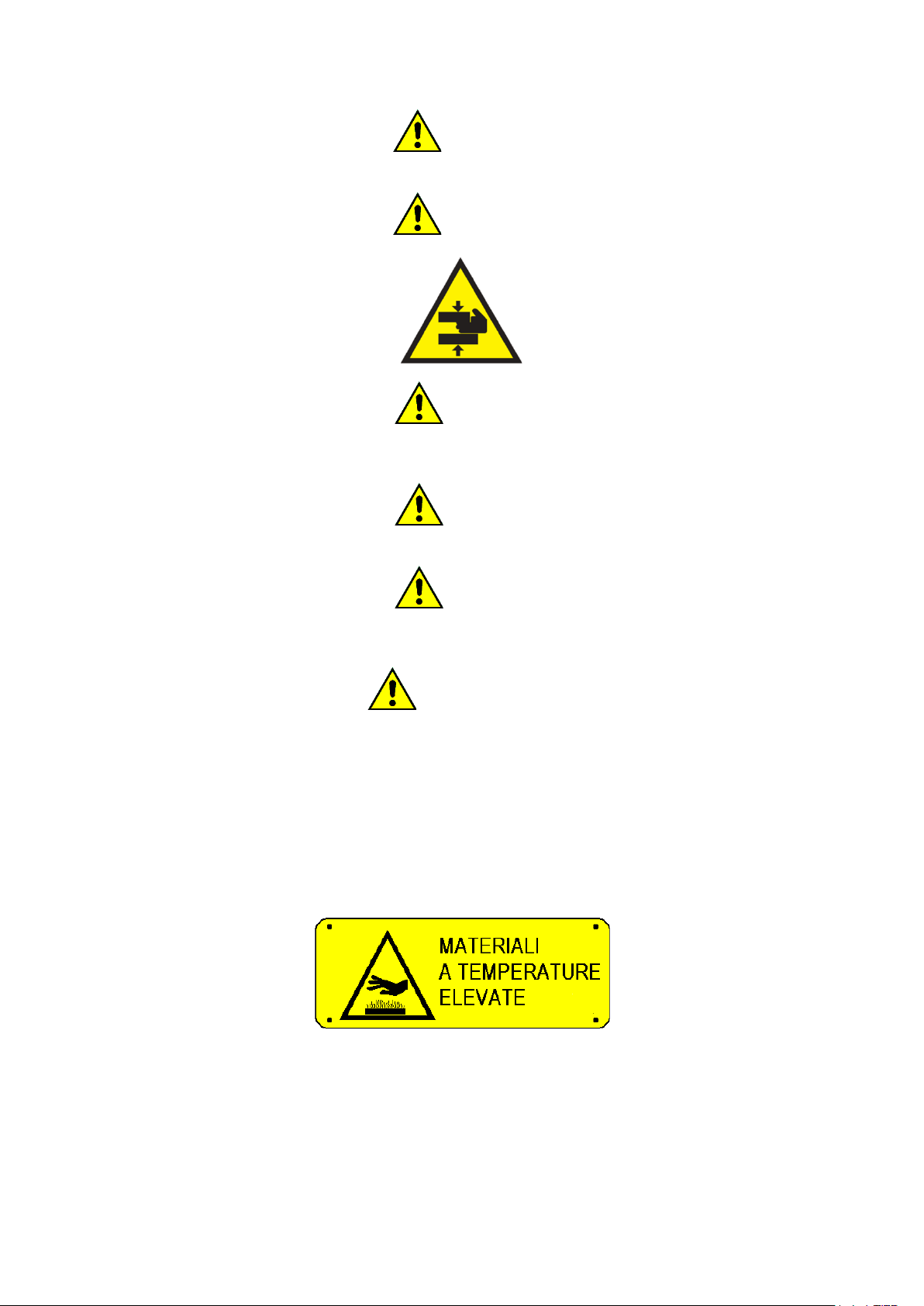
DANGER OF BURNS
The machine, by the very nature of the activity for which it is intended, presents the danger of burns.
Any burns can be caused:
-From contact with the fabric leaving the machine.
-From contact with the porthole following its opening.
-From the contact with the heating batteries during the maintenance operations performed "hot", that is,
without having first waited for the cooling of the machinery and its heating system.
-From contact with the components that convey the steam
The following plates have been affixed to the machine, in case of damage to them, the user must replace them
with identical ones.
The outer walls of the machine can reach high temperatures during operation
The machine must always and only be used by professionally trained personnel and in the presence of at least
one other operator!
CAREFULLY READ AND INFORM ALL OPERATORS ABOUT INTERVENTION SYSTEMS IN CASE OF SUDDEN
POWER FAILURE

E210501X rev.1_ENG 16/11/2021
7
DANGER OF ELECTROCUTION
Any intervention on the electrical parts of the machine must be carried out only by qualified personnel and after
removing the power supply to the machine.
The power and control circuits can only be tampered with by the manufacturer's staff, under penalty of forfeiture
of the warranty conditions.
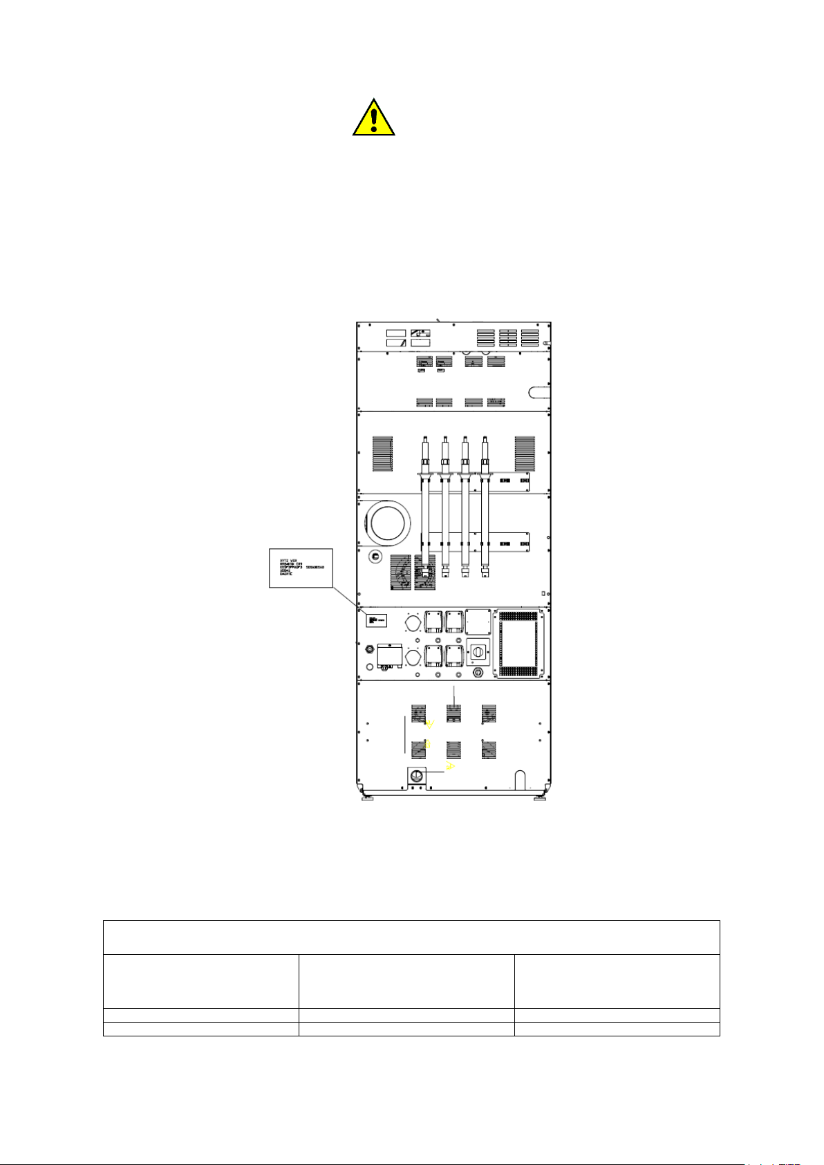
On the electrical panel there is the following monitor plate that must be replaced with an identical one in case it
has been damaged or removed.
It should be noted that, with reference to electrical hazards, the machine has been designed in accordance with
the standard and described in the certificate of conformity delivered with the machine.
PSYCHOPHYSICAL CONDITION OF THE OPERATOR
The operator in charge of the machine must be in perfect psychophysical condition; during the work, the vertical
posture in front of the machine must be assumed. Abrupt movements or uncontrolled gestures must be
avoided, for example during the removal and insertion of the fabrics to be dried to avoid dangerous collisions
with the machine frame.
If other operators or other personnel are present, these must not be a source of distraction for the operator in
charge of the machine.
During the use of the machine, the operator must not be distracted by televisions, radios, etc. nor be subject to
any other source of distraction.
The apparatus is not intended for use by persons whose physical or mental capacities are reduced, or with a
lack of experience or knowledge.
LIGHTING
In the room where the machine is installed, there must be uniform illumination of intensity 300-500 lux, annoying
glare must also be avoided.
ATTENTION!
These warnings do not cover all possible risks. The user must therefore proceed with the utmost caution in
compliance with the rules.
3. RESPONSIBILITY OF THE MANUFACTURER
The instructions in this manual do not replace but supplement the obligations for compliance with current
legislation on safety and accident prevention standards. With reference to what is reported in this manual, the
manufacturer declines all responsibility in the event of:
- use of the machine contrary to the laws in force on safety and accident prevention.
- incorrect installation of the machine.
- lack of periodic and scheduled maintenance
- failure or incorrect observance of the instructions provided in the manual.
- defects in voltage and mains supply.
- unauthorized modifications to the machine.
- use of the machine by unauthorized personnel.
E210501X rev.1_ENG 16/11/2021
8
4. TRANSPORT, STORAGE AND UNPACKING
The machinery must be transported and stored in rooms where temperature and humidity do not exceed the
following values:
- temperature: -25°C÷55°C
- Humidity: 0%÷90% (non-condensing)
Upon receipt it is recommended to check the machine, taking care to report to the carrier any damage caused
during transport, both to the internal components and to the external bodywork.
The machine must be completely unpacked near the place of installation.
The strapped straps must be cut, and the covering casing removed.
The packaging materials must not be dispersed in the environment and must be stored in the appropriate
collection spaces according to current regulations.
Remove with a wrench the fixing bolts to the pallet, visible at the base of the machine (front and rear).
ATTENTION!
Check on the technical sheet, attached to the machine documentation, the net and gross weight: check the
compatibility with the available lifting equipment.
ATTENTION!
The pallet should not be used as a normal machine holder! The machine must always be taken off the pallet and
positioned as described in the relevant paragraph.
ATTENTION!
The machine must be moved only when it is fixed to its pallet: the handling through the forklift must be carried
out only by qualified and competent personnel.
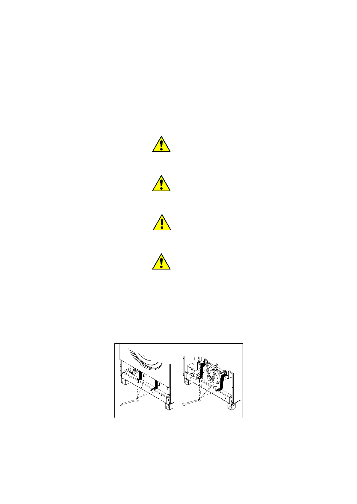
ATTENTION!
The latches must be removed, after the machine has been placed and before it is fed.
To disassemble the latches, perform the procedure described below, referring to the figure. The figures are
indicative of the type of stops and not of the machine.
- remove the back and front panels
- unscrew the bolts that block the transport stops
- dismantle transport stops
- reassemble the panels in the original position
All panels must be reassembled in the original position before the machine can be started. After removing them,
the retainers must be stored and reused whenever the machinery is to be transported.
5. INSTALLATION AND POSITIONING
All positioning and installation operations must be performed by professionally qualified personnel and

E210501X rev.1_ENG 16/11/2021
9
according to the instructions in the relevant installation manual.
ATTENTION!
If the machine cannot be installed respecting the criteria below, it is necessary to request the appropriate
transformations from the manufacturer.
Place the machine on a flat surface in a stable and horizontal way using the adjustable feet placed at the base
(where present). The adjustment of the feet is done from the outside, screwing, or unscrewing them until they
reach the bubble positioning.
For models that provide for it, adjustment can be made from inside the machine, after opening the filter door
and backrest, using a 5mm Allen wrench.
Check that the capacity of the floor is compatible with the weight of the machine that can be detected from the
data sheet. The load of the machine can be considered static. For the calculation of the static load remember
to add the net weight of the machine to the weight of the wet linen that will be loaded.
Make sure that the floor is clean and heat resistant.
For proper use, operation, and maintenance, leave a free space of at least 600 mm around the machine. For
battery machines, for example in self-service installations, the necessary side space can be reduced to 10mm.
The ambient temperature must be between +5°C and +40°C.
The smooth operation of the machinery is guaranteed in environments where the residual humidity is not higher
than 50% at a temperature of +40 ° C.
The degree of protection is IP24.
The environment in which the machinery is installed must have sufficient air exchange. In fact, it is recalled that
the machine takes the air from the environment in which it is installed and must discharge the humid process
air outside.
For the sizing of the air intakes refer to national regulations.
Consider a minimum of 9cm2/kW with a minimum surface area of 150cm2.
Remember that gratings and curtains reduce the flow rate of the vents.
The appliance must not be installed behind a lockable door, a sliding door, or a hinged door on the opposite side
to that of the drum dryer.
Do not install or use the machine if it is damaged.
Do not install the machine in a position where it is not possible to fully open the porthole (with the appropriate
kit, in some models, it is possible to rotate the front and make the door left or right).
ATTENTION!
Ensure the inflow of clean air to the machine and not air contaminated with chlorine, fluorine, or other solvent
vapors.
Do not use or store gasoline, petroleum, or other flammable materials in the vicinity of the car. It could cause
fires or explosions.
Provide in the vicinity of the machine a fire extinguisher chosen and kept in maintenance according to current
regulations.
ATTENTION!
The machine MUST NOT be installed outdoors, but in a CLOSED environment specifically built and used as a
laundry.
E210501X rev.1_ENG 16/11/2021
10
ATTENTION!
Check the cleanliness of the baskets. It is possible the presence of sheet metal processing residues in the inner
side of the basket surface.
6. MACHINE IDENTIFICATION
The equipment is identifiable by an adhesive plate bearing the serial number, model, power, and technical
characteristics. Make sure that the power supplies present (electrical, hydraulic, steam, gas, compressed air)
correspond to the license plate data.
Spare parts and / or interventions presuppose the exact identification of the model for which they are intended.
Tampering, removal, lack of identification plates or anything else that does not allow the safe identification of
the machine, makes any installation and maintenance operation difficult and automatically voids the warranty.
The machines described here are intended exclusively for washing in water and drying fabrics and are intended
for the commercial, professional, and industrial sectors.
MODELS AND MAXIMUM LOAD CAPACITY
MODELS AND MAX LOAD CAPACITY
TANDEM: O... (Or TDM xx/yy)
WASHING MACHINE LOADING
CAPACITY /
LOAD CAPACITY WASHER EXTRACTOR
(Kg)
LOAD CAPACITY DRYER /LOAD
CAPACITY TUMBLE DRYER
(Kg)
O11... (or TDM 11/11)
11 Kg (*)
11 Kg (*)
O88... (or TDM18/18)
18 Kg (*)
18 Kg (*)
Models with the capacities marked with (*) can be produced and equipped for installation in self-service stores

E210501X rev.1_ENG 16/11/2021
11
with coin, token, or other automatic payment systems. For some machines, the heating system of the washing
machine is hot water served.
7. INDICATIONS ON NOISE EMISSION
The airborne noise produced by the machine produces an A-weighted continuous sound pressure level,
described on the data sheet attached to the machinery documentation.
8. ELECTRICAL CONNECTION
ATTENTION!
The electrical connection must be carried out by professionally qualified personnel and must meet the
requirements of current local and national rules and / or regulations. Check that the supply voltage corresponds
to that indicated in the license plate data (voltage tolerance ±10%, frequency tolerance ±1Hz).
For the connection use a cable of type H05 VV –F or higher sized as reported in the license plate data and in
the technical sheet. Interpose upstream of the appliance an interlocked omni polar disconnection device (e.g., a
differential magnetothermal switch) with an opening between the contacts that allows complete disconnection
under the conditions of the surge category III and complies with the relevant regulations in force. The breaking
power of the circuit breaker shall be at least 10 kA.
Make sure the main circuit breaker of the machine is in the "0/OFF “position.
Open the inlet door for the power supply.
Pass the appropriately sized power cable (see tables below) through the cable press supplied with the machine.
Before letting the power cord in, make sure that it performs a dead neck lower than the input, so that any
condensation drops cannot come into contact with the electrical connections.
The connection of the power supply cables must be carried out on the on-board disconnector of the machine.
Depending on the type of power supply provided by the serial number plate of the machine, connect the wires
to the terminals marked as follows:
: terminal for the equipotential connection with the grounding system of the user.
L1, L2, L3: phase terminals
N: neutral terminal
When installing or replacing the power cord, the ground conductor must be at least 5 cm longer than the others.
ATTENTION!
Check the direction of rotation of the fan: it must rotate in such a direction as to expel the air from the exhaust:
the fan motor must turn in the direction of the arrow shown on its shell. Therefore, verify that the power supply
phases are connected in the correct sequence.
ATTENTION!
The appliance must be connected to an effective ground system: the manufacturer declines all responsibility in
the event that this connection is not carried out according to the provisions of the regulations in force on the
subject.
Before any maintenance operation, disconnect the power supply: for maintenance, refer to the wiring diagram
of the machine, inserted inside the machine or available on the manufacturer's website.
The minimum sections for power cables and ground cables, expressed in2mm, are described in the attached
data sheet.

E210501X rev.1_ENG 16/11/2021
12
ATTENTION!
The minimum sections shown may vary depending on the length of the connection. For lengths longer than 5
meters, increase the section proportionally to the additional length.
ATTENTION!
The connection of the machine must always be carried out according to the matricular data (power, supply
voltage, frequency). For supply voltages other than those envisaged, request information from the
manufacturer.
ATTENTION!
For machines equipped with speed regulation (of the basket or fan) and therefore equipped with a frequency
variator, it is specifically necessary to provide protection by RCD device of type B (sensitive to the average
current value).
ATTENTION!
For machines equipped with a power cable: if the power cord is damaged, it must be replaced by the
manufacturer or by the technical assistance service or in any case by a person with similar qualification, in order
to prevent any risk.
ATTENTION!
Before switching on an equipment that has undergone a thermal shock, wait for evaporation from any
condensed moisture to avoid possible damage to the electronic components.

E210501X rev.1_ENG 16/11/2021
13
TANDEM
MODEL
WASHING
MACHINE
HEATING
DRYER HEATING
VOLTAGE (V~)
[f=50/60 Hz]
CONSUMPTION
(A)
SUGGESTED
MINIMUM
CONDUCTOR
SECTION (mm2)
O11...
(TDM
11/11)
HOT WATER /
STEAM
ELECTRIC
3ph400V-480V (+N)
3ph230V
1ph230V
26
43
72
4
10
16
HOT WATER /
STEAM
GAS / STEAM
3ph400V-480V (+N)
3ph230V
1ph230V
5
6,5
9
2,5
2,5
2,5
ELECTRIC
ELECTRIC
3ph400V-480V (+N)
3ph230V
1ph230V
34
59
102
10
16
35
ELECTRIC
GAS / STEAM
3ph400V-480V (+N)
3ph230V
1ph230V
13
22,5
39
2,5
4
10
O88...
(TDM
18/18)
HOT WATER /
STEAM
ELECTRIC
3ph400V-480V (+N)
3ph230V
1ph230V
32
55,5
NOT
AVAILABLE.
6
16
NOT AVAILABLE.
HOT WATER /
STEAM
GAS / STEAM
3ph400V-480V (+N)
3ph230V
1ph230V
8
13,5
NOT
AVAILABLE.
2,5
2,5
NOT AVAILABLE.
ELECTRIC
ELECTRIC
3ph400V-480V (+N)
3ph230V
1ph230V
49
84
NOT
AVAILABLE.
6
25
NOT AVAILABLE.
ELECTRIC
GAS / STEAM
3ph400V-480V (+N)
3ph230V
1ph230V
25
42
NOT
AVAILABLE.
4
10
NOT AVAILABLE.
9. INSTALLATION: SPECIFICATIONS FOR GAS MACHINES
Any professional equipment with gas heating must be considered, regardless of the flow rate, a gas appliance.
During installation, the following requirements must be observed:
-municipal and / or territorial building system and fire regulations
-accident prevention regulations in force
E210501X rev.1_ENG 16/11/2021
14
-CENELEC provisions concerning electrical installations
-the "Standards for the safety of the use of combustible gas"
-the "Standards for gas plants powered by the distribution network or LPG gas"
-regulations of the body or company that dispenses or supplies the gas
-provisions of the entity supplying the electricity
-other possible local requirements
Openings for ventilation and ventilation of the room may be closed only if the opening condition is controlled
and if the operation of the fire sources of gas appliances is possible only in an open condition. The ventilation
of the room is optimal, even if the flue gases are mechanically sucked in, when the nominal thermal pollution of
these gas appliances does not give rise to any depression in the environment. This ensures a regular combustion
of the gas and a complete discharge of the flue gases.
To size the ventilation grilles, check the data reported in the technical data sheet and refer to the regulations in
force on the subject.
In the case of installation of liquid gas-fired dryers in sub-level premises of the ground, appropriate forced
ventilation devices shall be provided.
Gas data are collected in the specific paragraph of this manual.
ATTENTION!
Never install gas-heated machines in the same environment as machines using solvent solutions (e.g., dry
cleaning machines).
The combination could generate substances dangerous to the health of operators: it is also corrosive to steels.
If you place dryers with gas heating and machines that use solvents in two separate rooms, make sure that
there is no air exchange between the two rooms.
10. GAS CONNECTION
If the machine works with gas heating, make the appropriate connections with the distribution system: check
the license plate data of the machine, and in particular the pressure of the supply gas.
ATTENTION!
Please note that the maximum pressure for the gas valve is 50mbar. Gas supply even for a short time with
higher pressures, can damage the valve.
The gas distribution system must be made according to the regulations in force and with sections and pressures
appropriate to the appliance, see tables.
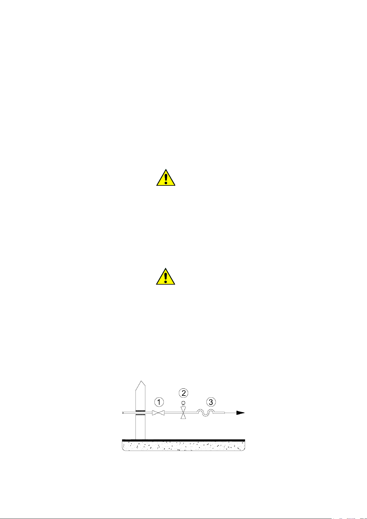
See figure below: a rapid-shut-off gas interception tap must be available upstream of the appliance (1); the gas
shut-off tap must be in the vicinity of the appliance and be in a position easily accessible to the user. This must
absolutely correspond to the requirements in force and be approved.
A minimum pressure switch must also be provided (2).
Connection to the gas supply system must be carried out with an anti-vibration joint (3); if flexible hoses are
used, they must be made of stainless-steel DIN 3384 or DIN 3383.
The system must be designed and executed in place according to current regulations. The gas connection on
the dryer has a section defined in the data sheet; this section should definitely not be reduced.

E210501X rev.1_ENG 16/11/2021
15
Finally, a scheme of principle for connection to the machine is reported, in the case of gas supply in a high-
pressure cylinder (liquid gas): in this case a two-stage reduction system is necessary, carried out according to
current regulations.
Downstream of the high-pressure cylinder (1) which serves as the tank, a first-stage regulator (1.5bar) must be
connected, followed by a suitably sized safety valve (2).
The high-pressure pipe (3) is interrupted by an interception tap (4) and continues, protected (5) under the
boundary of the compartmentalization area.
Before entering the compartment for use, it is necessary to provide a second shut-off valve and then the filter
(6) and the second stage stabilizer/regulator (7) which brings the pressure to the value intended for use.
11. GAS CONNECTION: LEAK TEST
All fittings between the system and the appliance are to be subjected to a leak test. For this operation it is
recommended to use leak-seeking sprays; otherwise, you can brush with other foamy substances, which do not
cause corrosion, the siding points; with both solutions no bubbles should occur.
ATTENTION!
It is absolutely forbidden to use open flames for the leak test!
12. GAS CONNECTION: THERMAL POWER
All equipment during the final testing at the factory is prepared for the type of gas reported on the adhesive plate
located near the serial number plate.
If the preparation of the appliance does not correspond to the family of gas available on site, it is mandatory to
carry out a transformation of the appliance for adaptation to the type of gas present. In this case it is absolutely
necessary to inform the authorized technical service center.
The commissioning of the appliance with the expected thermal power depends on the inlet pressure and calorific
value of the gas as well as the nozzle, the pressure to the same and the correct supply of primary air.
The inlet pressure that allows the operation of the apparatus is included for the several types of gas within the
limits set out in the following table. Outside these limits, the commissioning of the apparatus is prohibited. If a
pressure different from what is shown in the table is found, it is advisable to consult the body or company that
supplies the gas or the company that carried out the plant.
The lower calorific value of the gas is requested from the body or company that supplies the gas and must
correspond to what is reported in the technical sheet.
13. GAS CONNECTION: INLET PRESSURE CONTROL
The inlet pressure must be measured with a liquid or digital measuring instrument (resolution of at least 0.1
mbar).
- Close the eavesdropping device.
- Loosen the sealing screw of the gas valve pressure socket identified with "Pin".
- Connect the pressure gauge.
- Open the eavesdropping device.
- Operate the device according to the instructions for use.
- Measure the inlet pressure, with the burner on.
- Turn off the appliance.
- Close the eavesdropping device.
- Detach the pressure gauge.

E210501X rev.1_ENG 16/11/2021
16
- Close the sealing screw of the gas valve pressure socket and check the tightness.
- Open the eavesdropping device and check the tightness.
The commissioning of the appliance gaseous fuels is not permitted outside the pressure ranges set out in the
appropriate tables described below in this manual.
14. GAS CONNECTION: TESTING
As soon as the connection work is completed, the appliance and the entire installation must be checked. You
should check:
-that the connections are made in accordance with the requirements and indications of this manual.
-that all the safety requirements of the standards, laws and directives in force are met.
-that the gas connections made are leak tight.
The equipment is then switched on according to the instructions in the user manual, checking the progressive
ignition of the burners and the appearance of the flame.
Carry out a control of gas consumption by the volumetric method. Detecting through the meter how much gas
has been consumed in a given unit of time: the resulting value is to be compared with the values shown in the
table.
15. EXHAUST PIPE WET AIR AND FLUE GASES
The exhaust duct fumes, and humid air must be made according to current regulations.
To avoid leakage of moist air and noise, the exhaust joints from the machine to the outside must be made
airtight, with materials (stucco, mastics, silicone preparations) resistant to high temperatures.
To avoid pressure drops, avoid the use of spiral ducts: therefore, use smooth and rigid metal pipes. The material
used must be compatible with the exhaust temperatures of the machinery.
Gas-based dryers are gas appliances of type B22, i.e., gas appliances dependent on an aerated environment
without wind protection device with blower behind the combustion chamber.
Flue gases from a gas dryer must absolutely be conducted outdoors through the chimney.
The flue gas and humid air duct, as short as possible, should be inclined in ascending form towards the exhaust
chimney.
To reduce pressure drops, avoid 90° curves, preferring two 45° curves.
At the lowest point, a condensate trap must be provided, and the derivation of this trap must comply with the
local provisions for connection to the water drain.
The pipeline must withstand crushing.
In the case of input into a collector, do not make "T" connections and consider the correct value of the collector
section. If necessary, provide for an increase in the collector section.
Manifold for multiple machines cannot be performed for gas machines.
For machines with electric or steam heating you can provide for a collector: do not make "T" connections and
consider the correct value of the collector section. If necessary, provide for an increase in the collector section.

E210501X rev.1_ENG 16/11/2021
17
The dryer is equipped with an exhaust fan that produces its typical noise during operation.
To reduce the noise level, it is possible to mount a silencer (available at specialized stores) to be installed on the
exhaust.
ATTENTION!
The exhaust ducts of gas dryers must never be shared with the exhaust ducts of electric or steam heating dryers,
much less with the exhaust ducts of other types of machines.
ATTENTION!
The outlet of the exhaust pipe must not flow at human height and/or be directed towards residential units.
ATTENTION!
Instruct the user on the danger of tampering with the exhaust pipes and/or modifying, plugging, obstructing, or
reducing the ventilation openings of the installation space.
ATTENTION!
Do not insert your hands objects inside the drain. On this connection must be exclusively connected the smoke
evacuation chimney and humid air.
16. STEAM CONNECTION
16.1 STEAM WASHING MACHINE CONNECTION
Only for tandems equipped with washing machines with steam heating, it is necessary to make a connection to
the steam network. The connection must be carried out by professionally qualified personnel and must meet
the requirements of current local and national rules and/ or regulations. Verify that the steam has the
characteristics reported in the technical data sheets, and that all the plant components are certified.
The steam valve is delivered mounted: its electrical and hydraulic connection is by the installer.
ATTENTION!
Once the valve has been connected to the outside of the machine, the assembly must be protected by the metal
box supplied with it: see figure below.
E210501X rev.1_ENG 16/11/2021
18
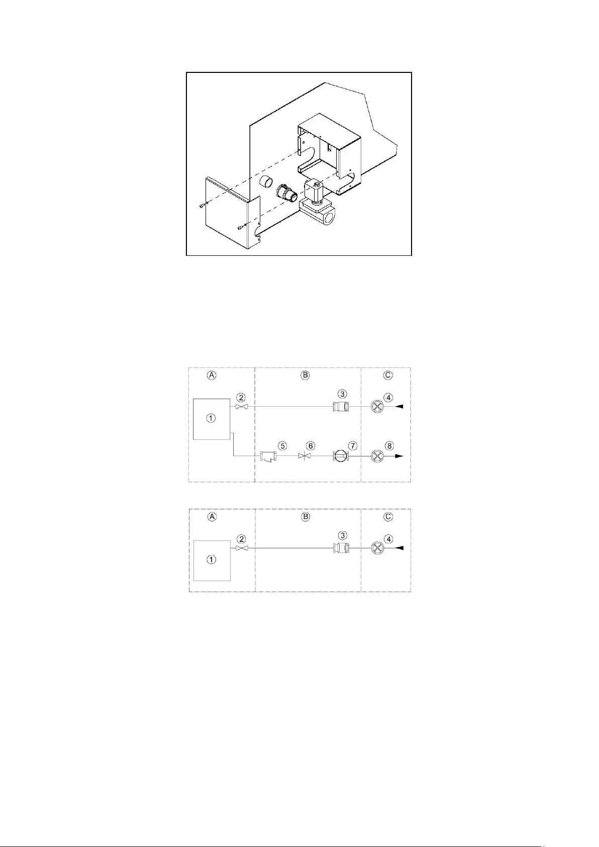
The steam supply system must be made according to the following scheme. Finally, all the connections between
the system and the appliance must be subjected to a leak test.
A) machine
B) external system
C) steam supply system
Heating: indirect steam:
Heating: direct steam
The elements of the plant are identified as follows in the schemes:
1) washing machine
2) steam valve (supplied)
3) filter
4) steam inlet gate
5) condensate trap
6) non-return valve
7) passage indicator
8) condensate outlet gate
9)

E210501X rev.1_ENG 16/11/2021
19
ATTENTION!
The machine can operate with a steam pressure of 0.5bar to 4.5 bar, but the lower the steam pressure, the
longer the water heating times in the washing phases.
ATTENTION!
For tilting machines make sure that the movement of the machine does not compromise the connection to the
steam collectors.
16.2 STEAM DRYER CONNECTION
Only for tandems with dryers equipped with steam heating, it is necessary to make a connection to the steam
network. The connection must be carried out by professionally qualified personnel and must meet the
requirements of current local and national rules and/ or regulations. Verify that the steam has the minimum
characteristics reported in the technical data sheets, and that all the system components are certified.
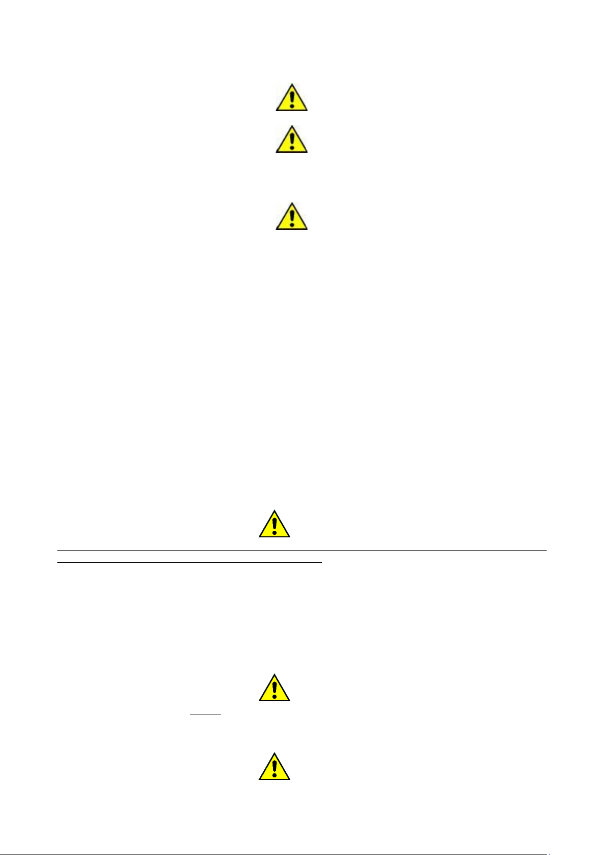
The plant must be made according to the following scheme:
The elements of the plant are identified as follows:
1. Shut-off valve
2. Filter
3. Pressure reducer (where necessary)
4. Safety valve
ATTENTION!
For the safety valve to be efficient, it must be sized to meet the maximum flow rate of the steam supply line
5. Empty breaker valve
6. Filter
7. Inverted bucket condensate trap
8. Passage indicator
IN Input to the steam exchanger of the machine
OUTUs exit from the machine exchanger
ATTENTION!
Drying performance depends on the performance of the steam exchanger.
The machine can operate in a pressure range (see data sheet) of the steam: but the lower the steam pressure,
the lower the performance of the machine. To prevent drying times from being too long, it is recommended to
have a minimum vapor pressure of 5bar.
E210501X rev.1_ENG 16/11/2021
20
ATTENTION!
The shut-off valve (1) must be opened slowly, so as to minimize the effects of water hammer.
ATTENTION!
The steam line MUST NOT be intercepted by electric or pneumatic valves for temperature regulation.
Thermoregulation is already carried out by the damper of the machine. The use of valves shortens the
life of the exchanger, and the warranty must be considered automatically lapsed.
ATTENTION!
Do not touch the steam inlet and outlet pipes when the machine is running or when the system is
running!
17. COMPRESSED AIR CONNECTION
The connection to the compressed air system is necessary only for some machine models: check the technical
data in this regard.
The plant must be carried out by professionally qualified personnel and must meet the requirements of current
local and national rules and / or regulations.
All fittings between the system and the appliance are to be subjected to a leak test. For this operation it is
recommended to use spray for leaks. In the event that there are leaks, proceed to their elimination.
18. HYDRAULIC CONNECTION: WATER LOAD
The tandem washing machines are equipped with solenoid valves for loading cold water and hot water (and
hard water for the models that provide it): each water inlet is identified: for the connection quotas refer to the
relative technical sheet.
Upstream of each hydraulic supply pipe must be provided a gate that allows at any time to interrupt the flow of
water to the machine, both for any emergency situations and for normal maintenance operations. An inspectable
water filter must be installed upstream of each inlet: it is also a good idea to check the filters of the load solenoid
valves, after a short period of use of the machine, especially if the pipes to which the connection has been made
are old or not used for a long time.
ATTENTION!
The water supply pressure must be between a minimum of 0.05 MPa and a maximum of 10 MPa. The water
inlet temperature must never be below 5°C and above 60°C.
(The minimum and maximum values consider all the different models of valves present in the varied sizes of
machinery).
The lower the supply pressure, the higher the loading times will be.
In the presence of several washing machines, the water load line must have a diameter that allows a rapid influx
even in the case of simultaneous loading of all washing machines.
ATTENTION!
All water loading valves must always be connected! If the system is not powered by hot water served, use cold
water to also feed the valve identified with "HOT WATER" and where present also the one identified as "HARD
WATER".
ATTENTION!
The HOT WATER heating system does not provide other autonomous or external forms of heating except the
This manual suits for next models
1
Table of contents
Other Imesa Washer manuals


Popular Washer manuals by other brands


Bosch
Bosch WAN28281GB User manual and installation instructions

FUST
FUST NOVAMATIC WA 712E user manual

Hotpoint Ariston
Hotpoint Ariston AQUALTIS AQS62L 09 Instructions for installation and use

Samsung
Samsung WA45K7100A series user manual

EAS Electric
EAS Electric Excellent EMW8545GW instruction manual

TCL
TCL P608FLW owner's manual

Raytheon
Raytheon SC18EC operating instructions

GE
GE GCXRP090 owner's manual

Alliance Laundry Systems
Alliance Laundry Systems 1305 Supplement

Siemens
Siemens WM16XGH1GB User manual and installation instructions

Frigidaire
Frigidaire GLEH1642FS owner's manual

Bosch
Bosch WAN series Instruction manual and installation instructions