IMG STAGE LINE LE-550DMX User manual

LICHTEFFEKTGERÄT
„TANDEM-SCANNER“
LIGHT EFFECT UNIT “TANDEM SCANNER”
JEU DE LUMIÈRE “SCANNER TANDEM”
UNITÀ PER EFFETTI LUCE “SCANNER TANDEM”
BEDIENUNGSANLEITUNG • INSTRUCTION MANUAL • MODE D’EMPLOI
ISTRUZIONI PER L’USO • GEBRUIKSAANWIJZING • MANUAL DE INSTRUCCIONES
SIKKERHEDSOPLYSNINGER • SÄKERHETSFÖRESKRIFTER • TURVALLISUUDESTA
LE-550DMX Best.-Nr. 38.1540

2
Ennen virran kytkemistä ...
Toivomme, että uusi “img Stage Line”-laitteesi
tuo sinulle paljon iloa ja hyötyä. Ole hyvä ja
lue käyttöohjeet ennen laitteen käyttöönottoa.
Luettuasi käyttöohjeet voit käyttää laitetta tur-
vallisesti ja vältyt laitteen väärinkäytöltä.
Käyttöohjeet löydät sivulta 24.
FIN
Bevor Sie einschalten ...
Wir wünschen Ihnen viel Spaß mit Ihrem
neuen Gerät von „img Stage Line“. Dabei soll
Ihnen diese Bedienungsanleitung helfen, alle
Funktionsmöglichkeiten kennen zu lernen. Die
Beachtung derAnleitung vermeidet außerdem
Fehlbedienungen und schützt Sie und Ihr Ge-
rät vor eventuellen Schäden durch unsachge-
mäßen Gebrauch.
Den deutschen Text finden Sie auf den Seiten
4–6.
D
A
CH
Avant toute mise en service ...
Nous vous remercions d’avoir choisi un ap-
pareil “img Stage Line” et vous souhaitons
beaucoup de plaisir à l’utiliser. Cette notice a
pour objectif de vous aider à mieux connaître
les multiples facettes de l’appareil. En outre,
en respectant les conseils donnés, vous évi-
terez toute mauvaise manipulation de sorte
que vous-même et votre appareil soient pro-
tégés de tout dommage.
La version française se trouve pages 10–12.
Antes de cualquier instalación ...
Tenemos de agradecerle el haber adquirido
un aparato “img Stage Line” y le deseamos
un agradable uso. Este manual quiere ayu-
darle a conocer las multiples facetas de este
aparato. La observación de las instrucciones
evita operaciones erróneas y protege Vd. y
vuestro aparato contra todo daño posible por
cualquier uso inadecuado.
La versión española se encuentra en las pá-
ginas 19–21.
NL
B
Inden De tænder for apparatet ...
Vi ønsker Dem god fornøjelse med Deres nye
“img Stage Line” apparat. Læs oplysningerne
for en sikker brug af apparatet før ibrug-
tagning. Følg sikkerhedsoplysningerne for at
undgå forkert betjening og for at beskytte
Dem og Deres apparat mod skade på grund
af forkert brug.
Sikkerhedsoplysningerne finder De på side 22.
DK
Before you switch on ...
We wish you much pleasure with your new
“img Stage Line” unit. With these operating
instructions you will be able to get to know all
functions of the unit. By following these in-
structions false operations will be avoided,
and possible damage to yourself and your
unit due to improper use will be prevented.
You will find the English text on pages 7–9.
Voordat u inschakelt ...
Wij wensen u veel plezier met uw nieuw toestel
van “img Stage Line”. Met behulp van bij-
gaande gebruiksaanwijzing zal u alle functie-
mogelijkheden leren kennen. Door deze in-
structies op te volgen zal een slechte werking
vermeden worden, en zal een eventueel letsel
aan uzelf en schade aan uw toestel tengevolge
van onzorgvuldig gebruik worden voorkomen.
U vindt de nederlandstalige tekst op de pagi-
na’s 16–18.
E
GB
I
S
Prima di accendere ...
Vi auguriamo buon divertimento con il Vostro
nuovo apparecchio “img Stage Line”. Le istru-
zioni per l’uso Vi possono aiutare a conoscere
tutte le possibili funzioni. E rispettando quanto
spiegato nelle istruzioni, evitate di commet-
tere degli errori, e così proteggete Voi stessi,
ma anche l’apparecchio, da eventuali rischi
per uso improprio.
Il testo italiano lo potete trovare alle pagine
13–15.
Förskrift
Vi önskar dig mycket nöje med din nya “img
Stage Line” enheten. Läs gärna säkerhetsin-
struktionerna innan du använder enheten.
Genom att följa säkerhetsinstruktionerna kan
många problem undvikas, vilket annars kan
skada enheten.
Dufinner säkerhetsinstruktionernapå sidan23.
F
B
CH
wwwwww..iimmggssttaaggeelliinnee..ccoomm

3
230
145
345
556
184
➀
➁
12 3
5
6
4
5
6
7
8

D
A
CH
4
Bitte klappen Sie die Seite 3 heraus. Sie sehen
dann immer die beschriebenen Bedienelemente
und Anschlüsse.
1 Übersicht der Bedienelemente und
Anschlüsse (Abb. 2)
1DMX-Eingang (3-pol. XLR)
2DMX-Ausgang (3-pol. XLR)
3Sicherung; eine durchgebrannte Sicherung nur
durch eine gleichen Typs ersetzen
4Kaltgerätebuchse für den Netzanschluss (230V~/
50Hz)
5Montagebügel
6Feststellschrauben
72 x DIP-Schalter für die Einstellungen im Master/
Slave-Betrieb und zur Einstellung der DMX-Start-
adresse und Umkehrung der Spiegeldrehrichtung
(Details siehe Kap. 6)
8Gewindebolzen für die Befestigung eines Monta-
gebügels in der Mitte des Gerätes
2 Hinweise für den sicheren Gebrauch
Dieses Gerät entspricht der Richtlinie für elektroma-
gnetische Verträglichkeit 89/336/EWG und der Nie-
derspannungsrichtlinie 73/23/EWG.
Beachten Sie unbedingt die folgenden Punkte:
●Das Gerät ist nur zur Verwendung in Innenräumen
geeignet. Schützen Sie es vor Tropf- und Spritz-
wasser, hoher Luftfeuchtigkeit und Hitze (zulässiger
Einsatztemperaturbereich 0–40°C).
●Während des Betriebs wärmt sich das Gerät sehr
stark auf. Um Verbrennungen zu vermeiden, berüh-
ren Sie das Gehäuse nicht während des Betriebs
bzw. lassen Sie das Gerät nach dem Ausschalten
einige Minuten abkühlen, bevor Sie es berühren.
●Die in dem Gerät entstehende Wärme muss durch
Luftzirkulation abgegeben werden. Darum dürfen
die Lüftungsöffnungen des Gehäuses nicht abge-
deckt werden.
●Stecken Sie nichts durch die Lüftungsöffnungen.
Dies kann zu einem elektrischen Schlag führen!
●Nehmen Sie das Gerät nicht in Betrieb bzw. ziehen
Sie sofort den Netzstecker aus der Steckdose, wenn:
1. sichtbare Schäden am Gerät oder an der Netz-
anschlussleitung vorhanden sind,
2. nach einem Sturz oder Ähnlichem der Verdacht
auf einen Defekt besteht,
3. Funktionsstörungen auftreten.
●Ziehen Sie den Netzstecker nie an der Zuleitung aus
der Steckdose.
●Verwenden Sie für die Reinigung nur ein trockenes,
weiches Tuch, niemals Wasser oder Chemikalien.
●Wird das Gerät zweckentfremdet, nicht richtig mon-
tiert, falsch bedient oder nicht fachgerecht repariert,
kann für eventuelle Schäden keine Haftung über-
nommen werden.
●Soll das Gerät endgültig aus dem Betrieb genom-
men werden, übergeben Sie es zur umweltgerech-
ten Entsorgung einem örtlichen Recyclingbetrieb.
3 Einsatzmöglichkeiten
Das Lichteffektgerät LE-550DMX ist besonders für
den Einsatz auf der Bühne und in Diskotheken geeig-
net. Das Gerät projiziert vielfarbige, unterschiedliche
geometrische Figuren und sorgt somit für eine ideale
Dancefloor-Atmosphäre. Die Lichtsteuerung erfolgt
über ein integriertes Mikrofon oder in Verbindung mit
einem Lichtsteuergerät über den DMX512-Anschluss.
Als Zubehör für die Steuerung des Tandem-Scan-
ners ist aus dem Programm von „img Stage Line“ der
DMX-Mini-Controller LE-550C (Bestell-Nr. 38.1600)
optional erhältlich.
4 Leuchtmittel einsetzen
Das Lichteffektgerät wird ohne Leuchtmittel geliefert.
Es werden zwei Halogenlampen 15V/150W mit einem
Sockel GZ6,35 (z.B. HLO-15/150MR aus dem Pro-
gramm von „img Stage Line“) benötigt.
Auf keinen Fall dürfen Lampen mit einer höheren
Leistungsangabe als 150W verwendet werden!
Die zwei Lampenfächer befinden sich links und rechts
an der Unterseite des Gehäuses.
1) Am jeweiligen Lampenfach die zwei schwarzen
Schrauben abschrauben und den Deckel des Lam-
penfachs öffnen.
2) Bei einem Lampenwechsel die alte Lampe aus der
Lampenhalterung ziehen und die Lampenfassung
abziehen.
3) Die Lampenfassung auf den Stiftsockel der neuen
Lampe stecken und die Lampe vorsichtig in die
Lampenhalterung schieben.
4) Den Deckel des Lampenfachs mit den zwei Schrau-
ben wieder fest verschließen.
Wichtig!
Ziehen Sie vor dem Einsetzen bzw. Herausnehmen
der Halogenlampen unbedingt den Netzstecker! Da
die Halogenlampen im Betrieb sehr heiß werden, las-
sen Sie sie nach Betrieb des Gerätes erst abkühlen
(Abkühlzeit mindestens 5 Minuten), bevor Sie sie
auswechseln.
Achtung!
Das Gerät wird mit lebensgefährlicher Netzspan-
nung (230V~) versorgt. Nehmen Sie deshalb nie
selbst Eingriffe im Gerät vor. Durch unsachgemä-
ßes Vorgehen besteht die Gefahr eines elektri-
schen Schlages. Lassen Sie das Gerät in jedem
Fall in einer Fachwerkstatt reparieren.

D
A
CH
5
5 Montage
Mit zwei Lichtstrahler-Halterungen bzw. zwei stabilen
Montageschrauben das Gerät über die beiden Monta-
gebügel (5) an der gewünschten Stelle (Traverse
eines Lichtstrahlerstativs oder Quergestänge) befesti-
gen. Das Gerät kann wahlweise auch über einen Mon-
tagebügel aufgehängt werden. In diesem Fall einen
der beiden Montagebügel an den Gewindebolzen (8)
in der Mitte des Gerätes anbringen.
ZumAusrichten des Gerätes die Feststellschrauben
(6) lösen, die gewünschte Neigung des Gerätes ein-
stellen und die Feststellschrauben wieder anziehen.
6 Bedienung
Das beiliegende Netzkabel mit Kaltgerätekupplung an
die Kaltgerätebuchse (4) anschließen und den Stecker
in eine Steckdose (230V~/50Hz) stecken. Bei An-
schluss an die Stromversorgung ist das Gerät einge-
schaltet. Nach dem Einschalten wird der Spiegel in
eine definierte Ausgangsstellung gebracht und die
Steuerung zurückgesetzt. Danach ist das Gerät be-
triebsbereit. Zum Ausschalten des Gerätes den Netz-
stecker ziehen.
Um einen besseren Bedienkomfort zu erhalten, ist
es empfehlenswert, das Gerät an eine Steckdose an-
zuschließen, die sich über einen Lichtschalter ein- und
ausschalten lässt.
6.1 Musiksteuerung
Um den Scanner über das integrierte Mikrofon zu
steuern, alle 8 DIP-Schalter von „Dipswitch A“ nach
unten in die ausgeschaltete Position stellen. Schalter 3
von „Dipswitch B“ wird in die „ON“-Stellung gebracht,
alle anderen Schalter auf die ausgeschaltete Position
stellen.
An der Musikanlage die Lautstärke so einstellen,
dass die Dynamik der Musik optimal durch die sich be-
wegenden Lichtstrahlen wiedergegeben wird.
6.1.1 Zusammenschalten mehrerer Scanner
Es lassen sich mehrere Scanner zusammenschalten,
um so über das Mikrofon des Hauptgerätes (Master)
alle weiteren Nebengeräte (Slave) im gleichen Rhyth-
mus zu steuern. Bis zu 16 Nebengeräte können über
ein Hauptgerät gesteuert werden.
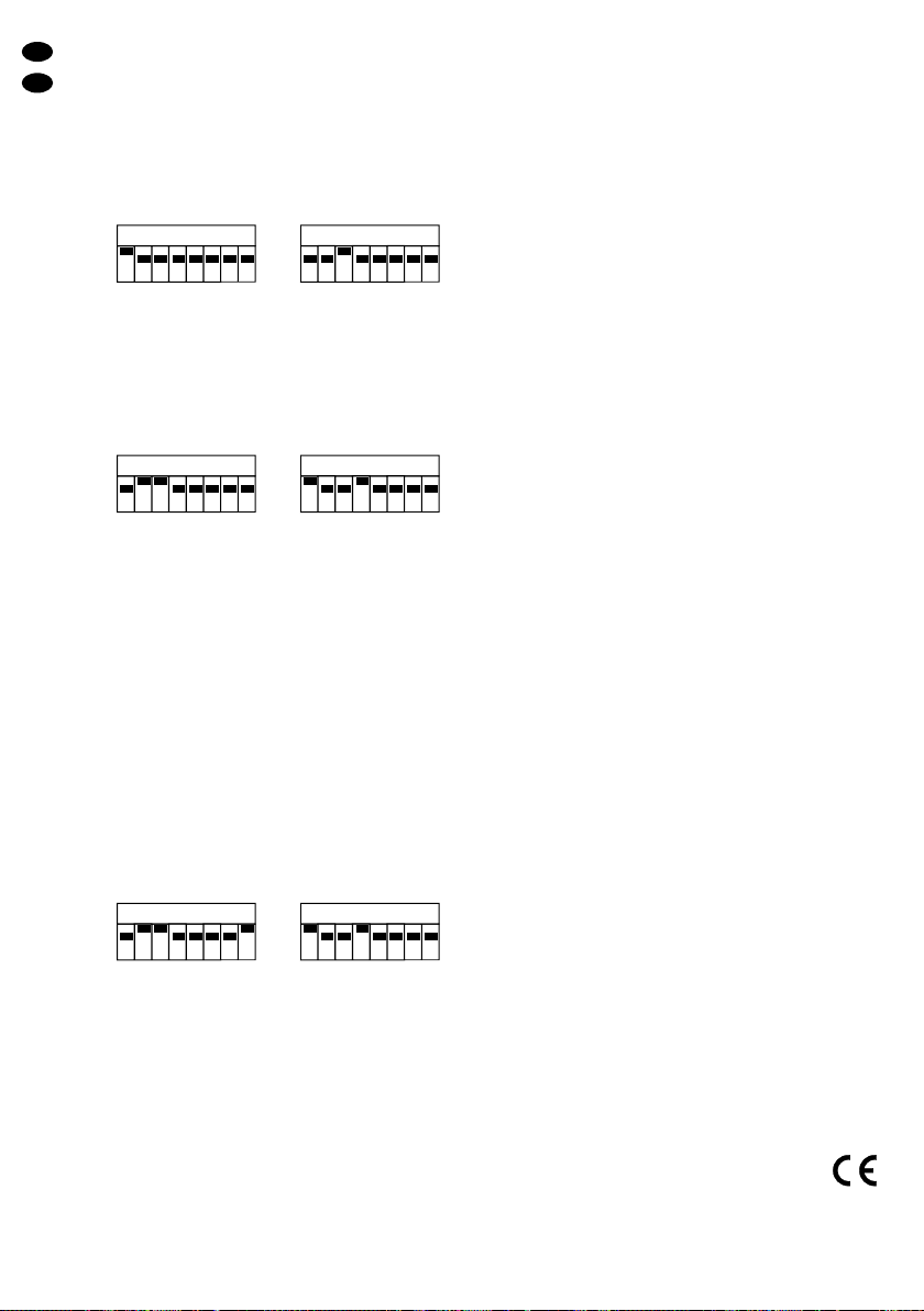
1) Am Hauptgerät die DIP-Schalter wie in Kap. 6.1
beschrieben einstellen.
➂Master mit aktiviertem Ausgang zur Slave-Ansteuerung
2) An allen Nebengeräten die DIP-Schalter wie unten
gezeigt (Abb. 4) einstellen.
➃Slave, Mikrofonsteuerung über Master
Für den Slave-Betrieb mit umgekehrter Spiegel-
drehrichtung beide DIP-Schalter 8 zusätzlich auf
„ON“ stellen:
➄Slave invers, Mikrofonsteuerung über Master
3) Den Ausgang (2) des Hauptgerätes über ein XLR-
Kabel mit dem Eingang (1) des ersten Nebengerä-
tes verbinden.
4) Den Ausgang des ersten Nebengerätes mit dem
Eingang des zweiten Nebengerätes verbinden usw.
Hinweis: Nach jeder Änderung der DIP-Schalter-Ein-
stellungen muss der Scanner durch Aus-und
Einschalten neu gestartet werden
6.2 Bedienung über ein Lichtsteuergerät
Das Lichteffektgerät LE-550DMX verfügt über fünf
DMX-Kanäle, die einzeln über ein DMX512-Steuer-
gerät gesteuert werden können:
1. Kanal 1 für die Ansteuerung der Farb-/Muster-
scheibe (Gobos) Geräteteil A
2. Kanal 2 für das An-/Ausschalten der Lampe Gerä-
teteil A
3. Kanal 3 für die Steuerung der Drehrichtung und der
Drehgeschwindigkeit des Spiegels
4. Kanal 4 für die Ansteuerung der Farb-/Muster-
scheibe (Gobos) Geräteteil B
5. Kanal 5 für das An-/Ausschalten der Lampe Gerä-
teteil B
1) Den Scanner über den Eingang (1) mit dem
DMX512-Steuergerät verbinden. Über den Aus-
gang (2) kann ein weiteres DMX512-kompatibles
Lichteffektgerät angeschlossen werden.
2) Die DIP-Schalter von „DipswitchA“ auf die Adresse
einstellen, die dem Kanal des DMX512-Steuer-
gerätes entspricht, der zur Steuerung von Kanal 1
des Lichteffektgerätes vorgesehen ist und die DIP-
Schalter von „Dipswitch B“ auf die Adresse, die
dem Kanal des DMX512-Steuergerätes entspricht,
der zur Steuerung von Kanal 4 des Lichteffekt-
gerätes vorgesehen ist.
Die Einstellung der DIP-Schalter erfolgt binär, d.h.
die Adressenvergabe erfolgt im 2er-System:
Schalter 1 entspricht 20(= 1), Schalter 2 ent-
spricht 21(= 2), Schalter 3 entspricht 22(= 4) usw.
Die Adressen werden durch „Addition“ der Schalter
eingestellt, z.B. 4 + 16 + 32 = Adresse 52. Die
Schalter 3, 5 und 6 hierfür in die Position ON stellen
12345678
O
N
Dipswitch B
12345678
O
N
Dipswitch A
12345678
O
N
Dipswitch B
12345678
O
N
Dipswitch A
12345678
O
N
Dipswitch B
12345678
O
N
Dipswitch A
Wichtig!
Zur Vermeidung von Wärmestaus im Gerät muss die
Montagestelle so gewählt werden, dass bei Betrieb
eine ausreichende Luftzirkulation gewährleistet ist.
Die Lüftungsöffnungen am Gehäuse dürfen nicht
abgedeckt werden (z.B. durch Vorhänge etc.).

D
A
CH
6
(22+ 24+ 25). Der höchste einzustellende Wert für
„Dipswitch A“ ist dieAdresse 123.
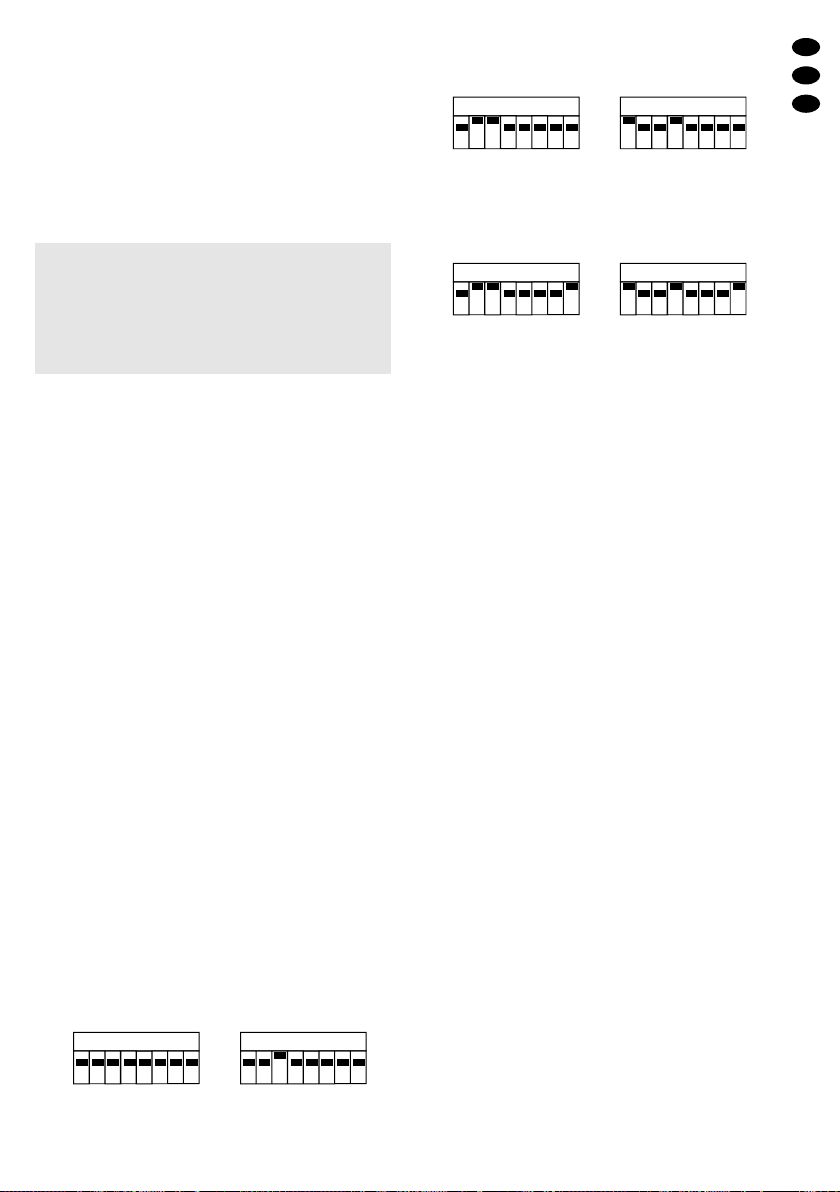
Einstellungsbeispiele:
Sind die Kanäle 1–5 des Steuergerätes für die
Steuerung vorgesehen, muss am Lichteffektgerät
mit den DIP-Schaltern A die Adresse 1 eingestellt
werden und mit den DIP-Schaltern B dieAdresse 4.
➅Adresse 1 für „Dipswitch A“, Adresse 4 für „Dipswitch B“
Sind die Kanäle 6–10 des Steuergerätes für die
Steuerung vorgesehen, muss am Lichteffektgerät
mit den DIP-Schaltern A die Adresse 6 eingestellt
werden und mit den DIP-Schaltern B dieAdresse 9.
➆Adresse 6 für „Dipswitch A“, Adresse 9 für „Dipswitch B“
Man erkennt, dass die Adresse auf „Dipswitch B“
immer drei Kanäle weiter als auf „Dipswitch A“ ein-
gestellt werden muss, um die Funktionen von Ge-
räteteil B zu steuern. Hat „Dipswitch B“ die gleiche
Adresse wie „Dipswitch A“, dann verhält sich Gerä-
teteil B genauso wie Geräteteil A.
3) Der DIP-Schalter 8 invertiert die Drehrichtung des
Spiegels. Wird dieser Schalter auf „ON“ gestellt,
dreht der Spiegel statt nach rechts nach links und
umgekehrt. So können synchrone Bewegungen
der angeschlossenen Scanner in entgegengesetz-
ten Richtungen realisiert werden.
Bei Steuerung über DMX darf aber nur der Schal-
ter 8 von „Dipswitch A“ auf „ON“ gestellt werden.
➇Umkehrung der Spiegeldrehrichtung
Hinweis: Nach jeder Änderung der DIP-Schalter-Ein-
stellungen muss der Scanner durch Aus-und
Einschalten neu gestartet werden
6.2.1 Beschreibung der Funktionen
Kanal 1 (Geräteteil A)
0–8: Lampe aus nach 20 Sekunden
9–16 kein Gobo (Blackout)
17–33: Gobo rund, weiß
34–50: Gobo rund, rot
51–67: Gobo rund, blau
68–84: Gobo rund, gelb
85–101: weißer Tunnel
102–118: sieben Bögen orange
119–135: Blüte magenta
136–152: Kleeblatt 7-blättrig, grün
153–169: Strahlen rot und blau
170–186: Fünfer-Stern türkis
187–203: Blume gelb
204–220: Vier-Farben-Tunnel
221–237: Acht Sterne blau
238–255: Schneller Wechsel der Gobos
Kanal 2 (Geräteteil A)
0–32: Lampe aus nach 20 Sekunden
33–255: Lampe an
Kanal 3
0–112: Der Spiegel bewegt sich im Uhrzeiger-
sinn (0 = max. Geschwindigkeit/112 =
min. Geschwindigkeit).
113–142: Der Spiegel bewegt sich nicht.
143–255: Der Spiegel bewegt sich gegen den
Uhrzeigersinn (143 = min. Geschwin-
digkeit/255 = max. Geschwindigkeit).
Kanal 4 (Geräteteil B)
0–8: Lampe aus nach 20 Sekunden
9–16 kein Gobo (Blackout)
17–33: Gobo rund, weiß
34–50: Gobo rund, rot
51–67: Gobo rund, blau
68–84: Gobo rund, gelb
85–101: weißer Tunnel
102–118: sieben Bögen orange
119–135: Blüte magenta
136–152: Kleeblatt 7-blättrig, grün
153–169: Strahlen rot und blau
170–186: Fünfer-Stern türkis
187–203: Blume gelb
204–220: Vier-Farben-Tunnel
221–237: Acht Sterne blau
238–255: Schneller Wechsel der Gobos
Kanal 5 (Geräteteil B)
0–32: Lampe aus nach 20 Sekunden
33–255: Lampe an
7 Technische Daten
Stromversorgung: . . . 230V~/50Hz
Leistungsaufnahme: . 320VA
Leuchtmittel: . . . . . . . 2 x Halogenlampe (15V/
150W), Sockel GZ 6,35
Abmessungen: . . . . . 556 x 145 x 184mm
(ohne Haltebügel)
Gewicht: . . . . . . . . . . 10,5kg
Laut Angaben des Herstellers.
Änderungen vorbehalten.
12345678
O
N
Dipswitch B
12345678
O
N
Dipswitch A
12345678
O
N
Dipswitch B
6432168421
12345678
O
N
Dipswitch A
6432168421
12345678
O
N
Dipswitch B
6432168421
12345678
O
N
Dipswitch A
6432168421

Please unfold page 3. Then you can always see the
operating elements and connections described.
1 Operating Elements and Connections
(fig. 2)
1DMX input (3-pole XLR)
2DMX output (3-pole XLR)
3Fuse; replace a burnt-out fuse by one of the same
type only
4Cold appliance chassis plug for mains connection
(230V~/50Hz)
5Mounting brackets
6Setscrews
72 x DIP switches for adjustments in the master/
slave mode and for adjusting the DMX start
address und reversing the sense of mirror rotation
(for details see chapter 6).
8Threaded bolt for fixing a mounting bracket in the
centre of the unit
2 Safety Notes
This unit corresponds to the directive for electromag-
netic compatibility 89/336/EEC and to the low voltage
directive 73/23/EEC.
Please observe the following items in any case:
●The unit is suitable for indoor use only. Protect it
against dripping water and splash water, high air
humidity, and heat (admissible ambient temperature
range 0–40°C).
●The unit heats up very much during operation. To
prevent burning yourself, never touch the housing
during operation; let the unit cool down for a few
minutes after switching off before you touch it.
●The heat generated within the unit must be carried
off by air circulation. Therefore, do not cover the air
vents of the housing.
●Do not insert anything into the air vents. This may
result in an electric shock!
●Do not operate the unit or immediately disconnect
the plug from the mains socket
1. if there is visible damage to the unit or to the
mains cable,
2. if a defect might have occurred after the unit was
dropped or suffered a similar accident,
3. if malfunctions occur.
●Never pull the mains cable for disconnecting the
mains plug from the socket.
●For cleaning only use a dry, soft cloth; never use
chemicals or water.
●No liability for any damage will be accepted if the
unit is used for other purposes than originally intend-
ed, if it is not correctly installed or operated or not
repaired in an expert way.
●If the unit is to be put out of operation definitively,
take it to a local recycling plant for a disposal which
is not harmful to the environment.
●Important for U.K. Customers!
The wires in this mains lead are coloured in accord-
ance with the following code:
green/yellow = earth
blue = neutral
brown = live
As the colours of the wires in the mains lead of this
appliance may not correspond with the coloured
markings identifying the terminals in your plug, pro-
ceed as follows:
1. The wire which is coloured green and yellow must
be connected to the terminal in the plug which is
marked with the letter Eor by the earth symbol ,
or coloured green or green and yellow.
2. The wire which is coloured blue must be con-
nected to the terminal which is marked with the
letter Nor coloured black.
3. The wire which is coloured brown must be con-
nected to the terminal which is marked with the
letter Lor coloured red.
Warning
-
This appliance must be earthed.
3 Applications
The light effect unit LE-550DMX is ideally suited for
stage and disco applications. The unit projects various
multicoloured geometric patterns providing an ideal
dance floor atmosphere. Light control is made via an
integrated microphone or in combination with a light
control unit via the DMX512 connection.
As an accessory for controlling the tandem scan-
ner, “img Stage Line” offers the miniature DMX con-
troller LE-550C (order No. 38.1600) to be ordered
separately.
4 Inserting the Lamps
The light effect unit is supplied without lamps. Two
halogen lamps 15V/150W with a GZ 6.35 lamp base
(e.g. HLO-15/150MR available from “img Stage Line”)
are required.
Never use lamps with a wattage higher than 150W!
The two lamp compartments are situated on the right
and the left of the lower side of the unit.
1) Unscrew the two black screws on the correspond-
ing lamp compartment and open the cover of the
lamp compartment.
Important!
Always disconnect the mains plug before inserting or
removing the halogen lamps! As the halogen lamps
heat up very much during operation, let them cool
down after operation of the unit (minimum cooling
time 5 minutes) before replacing them.
Attention!
The unit is supplied with hazardous mains voltage
(230V~). Inexpert handling may cause an electric
shock hazard. In any case the unit must be repair-
ed by skilled personnel.
GB
7

GB
8
2) When replacing a lamp, carefully remove the old
lamp from the lamp support and pull off the lamp-
holder.
3) Place the lampholder on the pin base of the new
lamp and carefully insert the lamp into the lamp
support.
4) Tightly close the cover of the lamp compartment
with the two screws.
5 Mounting
Use two supports for projectors or two sturdy mounting
screws to fix the unit via the two mounting brackets (5)
to the desired location (crossbar of a lighting stand or
horizontal T-bar). Alternatively, the unit can be sus-
pended from a single mounting bracket. In this case,
fix one of the two mounting brackets to the threaded
bolts (8) in the centre of the unit.
For aligning the unit, release the setscrews (6),
adjust the desired inclination of the unit and retighten
the setscrews.
6 Operation
Connect the supplied mains cable with cold appliance
inline jack to the cold appliance chassis plug (4), then
connect the mains plug to a socket (230V~/50Hz).
The unit is switched on as soon as it is connected to
the power supply. After switching on, the mirror is
placed in a defined starting position and the control is
reset. Then the unit is ready for operation. For switch-
ing off the unit, disconnect the mains plug.
For a more convenient operation, it is recommend-
ed to connect the unit to a mains socket which can be
switched on and off via a light switch.
6.1 Music control
For controlling the scanner via the integrated micro-
phone, set all 8 DIP switches of “Dipswitch A” down-
wards to the OFF position. Switch 3 of “Dipswitch B” is
set to “ON”, set all other switches to the OFF position.
Adjust the desired volume on the music system in
such a way that the moving light beams reproduce the
dynamic efficiency of the music in an optimum way.
6.1.1 Interconnecting several scanners
Several scanners can be interconnected in order to
control all other slave units to the same rhythm via the
microphone of the master unit. Up to 16 slave units
can be controlled via a master unit.
1) Set the DIP switches on the master unit as de-
scribed in chapter 6.1.
➂Master with activated output for slave control
2) Set the DIP switches on all slave units as shown
below (fig. 4).
➃Slave, microphone control via master
For slave operation with reversed sense of mirror
rotation, additionally set both DIP switches 8 to
“ON”:
➄Slave inverted, microphone control via master
3) Connect the output (2) of the master unit to the
input (1) of the first slave unit via an XLR cable.
4) Connect the output of the first slave unit to the input
of the second slave unit, etc.
Note: Restart the scanner after each modification of
the DIP switch adjustments, i.e. switch the
scanner off, then switch it on again.
6.2 Control via a light control unit
The light effect unit LE-550DMX is equipped with five
DMX channels which can be individually controlled via
a DMX512 controller:
1. Channel 1 for triggering the colour/pattern disk
(gobos), part Aof the unit
2. Channel 2 for for switching the lamp on and off, part
A of the unit
3. Channel 3 for controlling the sense of rotation and
the rotating speed of the mirror
4. Channel 4 for triggering the colour/pattern disk
(gobos), part B of the unit
5. Channel 5 for switching the lamp on and off, part B
of the unit
1) Connect the scanner to the DMX512 controller via
the input (1). Another DMX512 compatible light
effect unit can be connected via the output (2).
2) Adjust the DIP switches of “Dipswitch A” to the
address corresponding to the channel of the
DMX512 controller which is provided for controlling
channel 1 of the light effect unit, and adjust the DIP
switches of “Dipswitch B” to the address corre-
sponding to the channel of the DMX512 controller
which is provided for controlling channel 4 of the
light effect unit.
12345678
O
N
Dipswitch B
12345678
O
N
Dipswitch A
12345678
O
N
Dipswitch B
12345678
O
N
Dipswitch A
12345678
O
N
Dipswitch B
12345678
O
N
Dipswitch A
Important!
To prevent heat accumulation within the unit, the
mounting location must be selected in such a way
that a sufficient air circulation is ensured during op-
eration. The air vents of the housing must not be
covered (e.g. by curtains, etc.).

Binary adjustment of the DIP switches is made,
i.e. the address is assigned according to the power
of two:
Switch 1 corresponds to 20(= 1), switch 2 corre-
sponds to 21(= 2), switch 3 corresponds to 22
(= 4), etc. The addresses are adjusted by “addition”
of the switches, e.g. 4 + 16 + 32 = address 52. For
this purpose, set the switches 3, 5, and 6 to “ON”
(22+ 24+ 25). The highest value to be adjusted for
“Dipswitch A” is address 123.
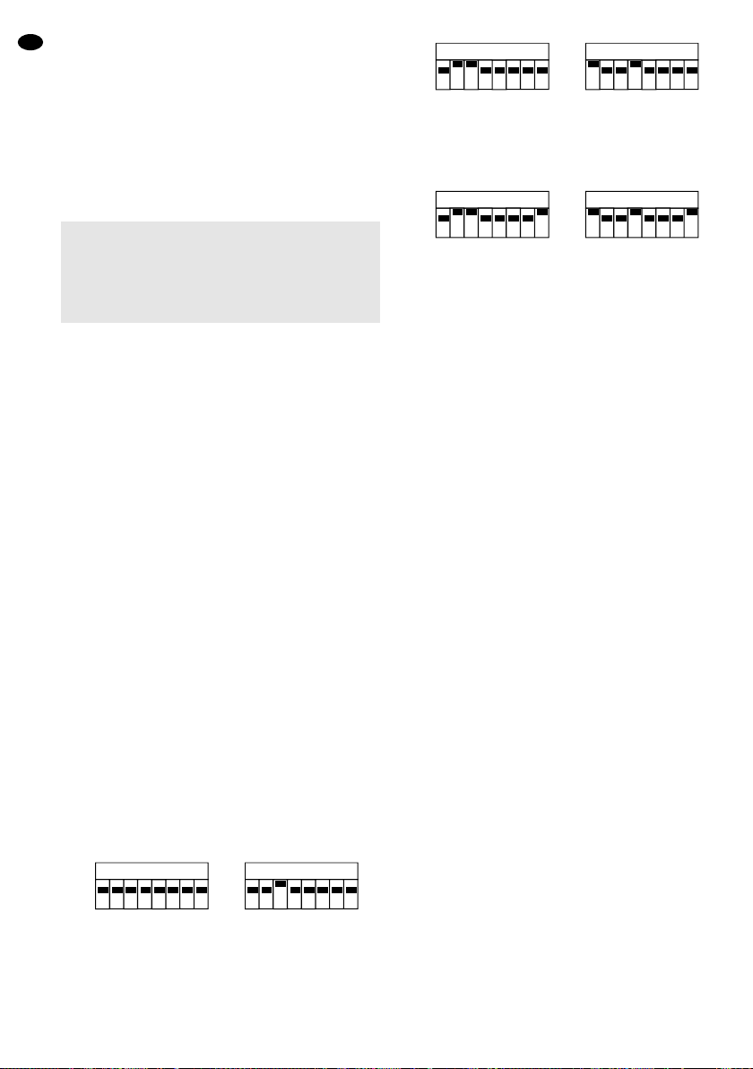
Adjusting examples:
If channels 1 to 5 of the controller are provided for
control, address 1 must be adjusted with the DIP
switches A and address 4 with the DIP switches B
on the light effect unit.
➅Address 1 for “Dipswitch A”, address 4 for “Dipswitch B”
If channels 6 to 10 of the controller are provided for
control, address 6 must be adjusted with the DIP
switches A and address 9 with the DIP switches B
on the light effect unit.
➆Address 6 for “Dipswitch A”, address 9 for “Dipswitch B”
It can be seen that for controlling the functions of
part B of the unit, the address on “Dipswitch B”
must always be adjusted 3 channels further than on
“Dipswitch A”. If “Dipswitch B” has the same
address as “DipswitchA”, part B of the unit behaves
like part Aof the unit.
3) DIP switch 8 inverts the sense of mirror rotation. If
this switch is set to “ON”, the mirror turns to the left
instead of turning to the right, and vice versa. Thus,
it is possible to realize synchronous movement of
the connected scanners in opposite directions.
However, in case of control via DMX, only switch
8 of “Dipswitch A” must be set to “ON”.
➇Reversing the sense of mirror rotation
Note: Restart the scanner after each modification of
the DIP switch adjustments, i.e. switch the
scanner off, then switch it on again.
6.2.1 Functional description
Channel 1 (part A of the unit)
0–8: lamp off after 20 seconds
9–16: no gobo (blackout)
17–33: gobo round, white
34–50: gobo round, red
51–67: gobo round, blue
68–84: gobo round, yellow
85–101: white tunnel
102–118: seven arcs, orange
119–135: blossom, magenta
136–152: seven-leaf clover, green
153–169: light beams, red and blue
170–186: pentagonal star, turquoise
187–203: flower, yellow
204–220: four-colour tunnel
221–237: eight stars, blue
238–255: rapid alternation of gobos
Channel 2 (part A of the unit)
0–32: lamp off after 20 seconds
33–255: lamp on
Channel 3
0–112: clockwise movement of the mirror
(0 = max. speed/112 = min. speed)
113–142: the mirror does not move
143–255: counterclockwise movement of the
mirror
(143 = min. speed/255 = max. speed)
Channel 4 (part B of the unit)
0–8: lamp off after 20 seconds
9–16: no gobo (blackout)
17–33: gobo round, white
34–50: gobo round, red
51–67: gobo round, blue
68–84: gobo round, yellow
85–101: white tunnel
102–118: seven arcs, orange
119–135: blossom, magenta
136–152: seven-leaf clover, green
153–169: light beams, red and blue
170–186: pentagonal star, turquoise
187–203: flower, yellow
204–220: four-colour tunnel
221–237: eight stars, blue
238–255: rapid alternation of gobos
Channel 5 (part B of the unit)
0–32: lamp off after 20 seconds
33–255: lamp on
7 Specifications
Power supply: . . . . . . 230V~/50Hz
Power consumption: . 320VA
Lamps: . . . . . . . . . . . 2 x halogen lamp
(15V/150W),
lamp base GZ 6.35
Dimensions: . . . . . . . 556 x 145 x 184mm (without
mounting brackets)
Weight: . . . . . . . . . . . 10.5kg
According to the manufacturer.
Subject to technical change.
12345678
O
N
Dipswitch B
12345678
O
N
Dipswitch A
12345678
O
N
Dipswitch B
6432168421
12345678
O
N
Dipswitch A
6432168421
12345678
O
N
Dipswitch B
6432168421
12345678
O
N
Dipswitch A
6432168421
GB
9

Ouvrez le présent livret page 3 de manière à visua-
liser les éléments et branchements.
1 Eléments et branchements (schéma 2)
1Entrée DMX (XLR 3 pôles)
2Sortie DMX (XLR 3 pôles)
3Fusible : tout fusible endommagé doit être rem-
placé par un fusible de même type
4Prise d’alimentation châssis pour une connexion
secteur 230V~/50Hz
5Etriers de montage
6Vis de fixation
72 x interrupteurs DIP pour effectuer les réglages
dans le mode de fonctionnement Master/Slave et
pour régler l’adresse de démarrage DMX et l’inver-
sion du sens de rotation du miroir (voir détails cha-
pitre 6)
8Boulon fileté pour fixer un étrier de montage au
milieu de l’appareil
2 Conseils d’utilisation et de sécurité
Cet appareil répond à la norme européenne
89/336/CEE relative à la compatibilité électroma-
gnétique et à la norme européenne 73/23/CEE por-
tant sur les appareils à basse tension.
Respectez scrupuleusement les points suivants :
●N’utilisez cet appareil qu’en intérieur. Protégez-le de
tout type de projections d’eau, des éclaboussures,
d’une humidité élevée et de la chaleur (plage de
température de fonctionnement autorisée : 0–40°C).
●Pendant le fonctionnement, l’appareil chauffe de
manière très importante. Pour éviter toute brûlure,
ne touchez jamais le boîtier pendant le fonctionnem-
ent ; une fois l’appareil éteint, laissez-le refroidir
quelques minutes avant de le toucher.
●La chaleur émise par l’appareil doit être dégagée
par une circulation d’air correcte. En aucun cas, les
ouïes de ventilation ne doivent être obturées.
●Ne faites rien tomber dans les ouïes de ventilation,
vous pourriez vous électrocuter!
●Ne faites pas fonctionner l’appareil ou débranchez
le immédiatement du secteur lorsque :
1. des dommages apparaissent sur l’appareil ou sur
le cordon secteur,
2. après une chute ou un cas similaire, vous avez un
doute sur l’état de l’appareil,
3. des défaillances apparaissent.
●Ne débranchez jamais l’appareil en tirant sur le cor-
don secteur.
●Pour le nettoyer, utilisez un chiffon sec et doux, en
aucun cas, de produits chimiques ou d’eau.
●Nous déclinons toute responsabilité en cas de dom-
mage si l’appareil est utilisé dans un but autre que
celui pour lequel il a été conçu, s’il n’est pas correc-
tement installé, utilisé ou n’est pas réparé par une
personne habilitée.
●Lorsque l’appareil est définitivement retiré du ser-
vice, vous devez le déposer dans une usine de recy-
clage adaptée pour contribuer à son élimination non
polluante.
3 Possibilités d’utilisation
Le jeu de lumière LE-550DMX (“Scanner Tandem”) est
bien adapté pour une utilisation sur scène et en disco-
thèque. Il projète des figures géométriques de formes
diverses, multicolores et permet ainsi de créer une
atmosphère “dance”. La gestion de la lumière se fait
par un microphone intégré ou en liaison avec un con-
trôleur via la connexion DMX512.
Comme accessoire pour gérer les fonctions de
l’appareil, vous trouverez dans la gamme “img Stage
Line” le mini contrôleur DMX, télécommande :
LE-550C (ref. num. 38.1600), disponible en option.
4 Insertion des lampes
L’appareil est livré sans lampes. Deux lampes halogè-
nes 15V/150W avec un culot GZ 6,35 (HLO-15/
150MR de la gamme “img Stage Line” p.ex.) sont
nécessaires.
En aucun cas, les lampes d’une puissance supé-
rieure à 150W ne doivent être utilisées !
Les deux compartiments lampe sont situés à droite et
à gauche de la partie inférieure de l’appareil.
1) Dévissez les deux vis noires sur le compartiment
lampe concerné et ouvrez le couvercle du compar-
timent lampe.
2) Pour remplacer la lampe, retirez l’ancienne lampe
du support puis retirez la douille de la lampe.
3) Placez la douille sur le culot de la nouvelle lampe
puis poussez avec précaution la lampe sur le sup-
port.
4) Fermez le couvercle du compartiment lampe avec
les deux vis.
Important !
Avant d’insérer ou retirer les lampes halogènes, vous
devez impérativement débrancher l’appareil du sec-
teur. Pendant le fonctionnement, les lampes sont
chaudes, vous devez les laisser refroidir après toute
utilisation et avant tout remplacement (refroidisse-
ment pendant 5 minutes au moins).
Attention !
L’appareil est alimenté par une tension dange-
reuse 230V~. Ne touchez jamais l’intérieur de l’ap-
pareil car en cas de mauvaise manipulation, vous
pourriez subir une décharge électrique mortelle.
Faites toujours appel à un technicien spécialisé
pour effectuer les réparations.
F
B
CH
10
5 Montage
Fixez l’appareil à l’endroit souhaité (traverse d’un pied
de lumière ou barre transversale) à l’aide de deux sup-
ports de projecteur ou de deux vis de montage stables
via les deux étriers de montage (5). L’appareil peut au
choix également être suspendu via un seul étrier de
montage ; dans ce cas, un des deux étriers de mon-
tage doit être fixé aux boulons filetés (8) au milieu de
l’appareil.
Pour orienter l’appareil, desserrez les vis de fixation
(6), donnez l’orientation voulue puis resserrez les vis.
6 Fonctionnement
Reliez le cordon secteur livré, doté d’une prise d’ali-
mentation femelle à la prise d’alimentation (4) de l’ap-
pareil et la prise mâle à une prise secteur 230V~/
50Hz. L’appareil est allumé lorsque la connexion d’ali-
mentation est effectuée. Une fois l’appareil sous ten-
sion, le miroir est placé dans une position de départ
définie et la commande est réinitialisée. L’appareil est
ensuite prêt à fonctionner. Pour éteindre l’appareil,
débranchez le cordon secteur.
Pour un meilleur confort d’utilisation, il est recom-
mandé de relier l’appareil à une prise secteur pouvant
être allumée et éteinte via un interrupteur.
6.1 Gestion via la musique
Pour commander le scanner via le microphone inté-
gré, mettez les 8 interrupteurs DIP de “Dipswitch A”
vers le bas sur la position d’arrêt. Mettez l’interrupteur
3 de “Dipswitch B” sur la position “ON”, et les autres
interrupteurs sur la position d’arrêt.
Réglez, sur l’installation audio, le volume de sorte
que la dynamique de la musique soit restituée de
manière optimale par les faisceaux lumineux en mou-
vement.
6.1.1 Possibilité de fonctionnement Master/
Slave entre plusieurs scanners
Il est possible de faire fonctionner ensemble plusieurs
scanners pour commander d’autres appareils auxiliai-
res (Slave) sur le même rythme, via le micro de l’ap-
pareil principal (Master). 16 appareils auxiliaires au
plus peuvent être gérés par un appareil principal.
1) Sur l’appareil principal (Master), mettez tous les inter-
rupteurs DIP comme décrit dans le chapitre 6.1.
➂Master avec sortie activée pour une commande slave
2) Sur tous les appareils auxiliaires (Slave), mettez
les interrupteurs DIP comme indiqué ci-dessous
(schéma 4).
➃Slave, commande micro via le Master
Pour le mode “Slave” avec rotation inversée du
miroir, mettez, en plus, les deux interrupteurs DIP 8
sur “ON” :
➄Slave inversé, commande micro via Master
3) Reliez la sortie (2) de l’appareil principal via un cor-
don XLR à l’entrée (1) du premier appareil auxi-
liaire.
4) Reliez la sortie du premier appareil auxiliaire à l’en-
trée du deuxième appareil auxiliaire et ainsi de
suite.
Conseil : après chaque modification des réglages des
interrupteurs DIP, le scanner doit être redé-
marré en l’éteignant puis le rallumant.
6.2 Utilisation via un contrôleur
Le jeu de lumière LE-550DMX dispose de 5 canaux
DMX qui peuvent être gérés séparément par une unité
de commande DMX512 :
1. canal 1 pour la commande des gobos/modèles de
couleurs, partie Ade l’appareil
2. canal 2 pour la marche/arrêt de la lampe, partie A
de l’appareil
3. canal 3 pour la commande du sens et de la vitesse
de rotation du miroir
4. canal 4 pour la commande des gobos/modèles de
couleurs, partie B de l’appareil
5. canal 5 pour la marche/arrêt de la lampe, partie B
de l’appareil
1) Reliez le scanner via l’entrée (1) à l’unité de com-
mande DMX512 ; via la sortie (2), il est possible de
relier un autre jeu de lumière compatible DMX512.
2) Réglez les interrupteurs DIP de “Dipswitch A” sur
l’adresse qui correspond au canal de l’unité de
commande DMX512, prévu pour gérer le canal 1
du jeu de lumière. Mettez les interrupteurs DIP de
“Dipswitch B” sur l’adresse qui correspond au canal
de l’unité de commande DMX512 prévu pour gérer
le canal 4 de l’appareil.
Le réglage des interrupteurs DIP s’effectue de
manière binaire, c’est-à-dire que l’adresse est attri-
buée selon la puissance de 2 :
L’interrupteur 1 correspond à 20(= 1), l’interrup-
teur 2 à 21(= 2), l’interrupteur 3 à 22(= 4) etc. Les
adresses sont réglées par “l’addition” des interrup-
teurs, p.ex. 4 + 16 + 32 = adresse 52. Dans ce cas,
12345678
O
N
Dipswitch B
12345678
O
N
Dipswitch A
12345678
O
N
Dipswitch B
12345678
O
N
Dipswitch A
12345678
O
N
Dipswitch B
12345678
O
N
Dipswitch A
Important !
Pour éviter toute accumulation de chaleur dans l’ap-
pareil, le lieu de montage doit être choisi de telle
sorte que pendant le fonctionnement, la circulation
d’air est suffisante. Les ouïes de ventilation sur le
boîtier ne doivent en aucun cas être obturées (par
des rideaux.. p.ex.).
F
B
CH
11

les interrupteurs 3, 5 et 6 doivent être sur la position
“ON” (22+ 24+ 25). La valeur la plus haute pouvant
être réglée pour “Dipswitch A”, est l’adresse 123.
Exemples de réglage
Si les canaux 1 – 5 de l’unité de commande sont
prévus pour la commande, il faut régler, avec les
interrupteurs DIP A, l’adresse 1 sur le jeu de lu-
mière et avec les interrupteurs DIP B l’adresse 4.
➅adresse 1 pour “Dipswitch A”,
adresse 4 pour “Dipswitch B”
Si les canaux 6 – 10 de l’unité de commande sont
prévus pour la commande, il faut régler, avec les
interrupteurs DIP A, l’adresse 6 sur le jeu de lu-
mière et avec les interrupteurs DIP B l’adresse 9.
➆adresse 6 pour “Dipswitch A”,
adresse 9 pour “Dipswitch B”
On note que l’adresse sur le “Dipswitch B” doit tou-
jours être réglée 3 canaux de plus que sur le “Dip-
switch A” pour gérer les fonctions de la partie B de
l’appareil. Si “Dipswitch B” a la même adresse que
“Dipswitch A”, la partie B de l’appareil se comporte
comme la partie A.
3) L’interrupteur DIP 8 intervertit le sens de rotation du
miroir. Si cet interrupteur est sur “ON”, le miroir
tourne vers la gauche au lieu de la droite et inver-
sement. Il est ainsi possible de réaliser des mouve-
ments synchrones des scanners connectés dans
des directions opposées.
Dans le cas d’une gestion par DMX, seul l’inter-
rupteur 8 de “Dipswitch A” doit être mis sur “ON”.
➇inversion du sens de rotation du miroir
Conseil : après chaque modification des réglages des
interrupteurs DIP, le scanner doit être redé-
marré en l’éteignant puis le rallumant.
6.2.1 Description des fonctions
Canal 1 (partie A)
0–8 arrêt de la lampe après 20 secondes
9–16 pas de gobo (blackout)
17–33 gobo rond, blanc
34–50 gobo rond, rouge
51–67 gobo rond, bleu
68–84 gobo rond, jaune
85–101 tunnel blanc
102–118 7 arcs oranges
119–135 fleur magenta
136–152 trèfle 7 feuilles, vert
153–169 rayons, rouge et bleu
170–186 étoile à 5 branches, turquoise
187–203 fleur, jaune
204–220 tunnel 4 couleurs
221–237 8 étoiles, bleu
238–255 changement rapide des gobos
Canal 2 (partie A)
0–32 arrêt de la lampe après 20 secondes
33–255 lampe marche
Canal 3
0–112 le miroir bouge dans le sens des aiguil-
les d’une montre (0 = vitesse maxi-
male/112 = vitesse minimale)
113–142 le miroir ne bouge pas
143–255 le miroir bouge dans le sens inverse
des aiguilles d’une montre (143 =
vitesse minimale/255 = vitesse maxi-
male)
Canal 4 (partie B)
0–8 arrêt de la lampe après 20 secondes
9–16 pas de gobo (blackout)
17–33 gobo rond, blanc
34–50 gobo rond, rouge
51–67 gobo rond, bleu
68–84 gobo rond, jaune
85–101 tunnel blanc
102–118 7 arcs oranges
119–135 fleur magenta
136–152 trèfle 7 feuilles, vert
153–169 rayons, rouge et bleu
170–186 étoile à 5 branches, turquoise
187–203 fleur, jaune
204–220 tunnel 4 couleurs
221–237 8 étoiles, bleu
238–255 changement rapide des gobos
Canal 5 (partie B)
0–32 arrêt de la lampe après 20 secondes
33–255 lampe marche
7 Caractéristiques techniques
Alimentation : . . . . . . 230V~/50Hz
Consommation : . . . . 320VA
Lampe : . . . . . . . . . . . 2 x lampe halogène
15V/150W,
culot GZ 6,35
Dimensions : . . . . . . . 556 x 145 x 184mm
(sans étriers de montage)
Poids : . . . . . . . . . . . . 10,5kg
D’après les données du constructeur
Tout droit de modification réservé
12345678
O
N
Dipswitch B
12345678
O
N
Dipswitch A
12345678
O
N
Dipswitch B
6432168421
12345678
O
N
Dipswitch A
6432168421
12345678
O
N
Dipswitch B
6432168421
12345678
O
N
Dipswitch A
6432168421
F
B
CH
12

Vi preghiamo di aprire completamente la pagina 3.
Così vedrete sempre gli elementi di comando e i
collegamenti descritti.
1 Elementi di comando e collegamenti
(fig. 2)
1Ingresso DMX (XLR a 3 poli)
2Uscita DMX (XLR a 3 poli)
3Fusibile; sostituire solo con uno dello stesso tipo
4Presa rete (230V~/50Hz) per apparecchi freddi
5Staffe di montaggio
6Viti di bloccaggio
72 x dip-switch per le regolazioni durante il funzio-
namento master/slave e per impostare l’indirizzo
di avvio DMX e per invertire il senso di rotazione
dello specchio (per particolari vedi cap. 6)
8Perno filettato per il fissaggio di una staffa di mon-
taggio nel centro dell’apparecchio
2 Avvertenze di sicurezza
Quest’apparecchio corrisponde alle direttive CE
89/336/CEE sulla compatibilità elettromagnetica e
73/23/CEE per apparecchi a bassa tensione.
Si devono osservare assolutamente i seguenti punti:
●L’unità è prevista solo per l’uso all’interno di locali.
Proteggerla dall’acqua gocciolante e dagli spruzzi
d’acqua, dall’umidità e dal calore (temperatura d’im-
piego ammessa fra 0°C e 40°C).
●Durante il funzionamento, l’unità si riscalda molto.
Per evitare delle bruciature, non toccarla durante il
funzionamento, e dopo averla spento lasciarla raf-
freddarsi per alcuni minuti prima di toccarla.
●Deve essere garantita la libera circolazione dell’
aria per dissipare il calore che viene prodotto all’in-
terno dell’apparecchio. Non coprire in nessun modo
le fessure di aerazione.
●Non inserire oggetti nelle fessure di aerazione. Altri-
menti si potrebbe provocare una scarica elettrica!
●Non mettere in funzione l’apparecchio e staccare
subito la spina rete se:
1. l’apparecchio o il cavo rete presentano dei danni
visibili;
2. dopo una caduta o dopo eventi simili sussiste il
sospetto di un difetto;
3. l’apparecchio non funziona correttamente.
●Staccare il cavo rete afferrando la spina, senza ti-
rare il cavo.
●Per la pulizia usare solo un panno morbido, asciutto;
non impiegare in nessun caso prodotti chimici o
acqua.
●Nel caso di uso improprio, di montaggio sbagliato, di
impiego scorretto o di riparazione non a regola
d’arte non si assume nessuna responsabilità per
eventuali danni.
●Se si desidera eliminare l’apparecchio definitiva-
mente, consegnarlo per lo smaltimento ad un’istitu-
zione locale per il riciclaggio.
3 Possibilità d’impiego
L’unità per effetti di luce LE-550DMX è prevista spe-
cialmente per l’uso professionale. Gli apparecchi pro-
iettano differenti figure geometriche variopinte cre-
ando in questo modo una suggestiva atmosfera da
pista da ballo. La luce è pilotata da un microfono inte-
grato oppure da un apposita unità di comando tramite
il collegamento DMX512.
Come accessorio per pilotare lo scanner tandem,
dal programma di “img Stage Line” è disponibile come
opzione il Mini controller DMX LE-550C (numero d’or-
dinazione 38.1600).
4 Inserire le lampadine
L’unità viene consegnata senza lampadine. È richiesta
due lampade alogene 15V/150W con zoccolo GZ
6,35 (p.es. HLO-15/150MR dal programma di “img
Stage Line”).
Non usare assolutamente lampade con potenza
superiore a 150W!
I due vani lampade si trovano a destra e a sinistra sul
lato inferiore dell’unità.
1) Svitare le due viti nere del vano lampade e aprire il
coperchio.
2) Per sostituire una lampada, togliere la vecchia lam-
pada dal suo supporto e sfilare il portalampada.
3) Montare il portalampada sullo zoccolo della nuova
lampada e spingere la lampada delicatamente nel
supporto.
4) Richiudere bene il vano lampada con le due viti.
Importante!
Staccare l’unità assolutamente dalla corrente prima
di inserire o sostituire le lampade! Poiché le lampade
si riscaldano moltissimo durante il funzionamento,
conviene lasciarle raffreddarsi dopo il funzionamento
(minimo 5 minuti), prima di sostituirle.
Attenzione!
L’unità funziona con tensione di rete di 230 V~. Non
intervenire mai al suo interno; la manipolazione
scorretta può provocare delle scariche pericolose.
Per la riparazione rivolgersi sempre ad una officina
competente.
I
13
5 Montaggio
Fissare l’unità attraverso le due staffe di montaggio (5)
nel punto desiderato (p.es. alla traversa di uno sta-
tivo), servendosi di due supporti per spot o di due viti
robuste di montaggio. A scelta, l’apparecchio può
essere sospeso anche con un una sola staffa di mon-
taggio. In questo caso, fissare una delle due staffe ai
perni filettati (8) nel centro dell’apparecchio.
Per orientare l’unità, allentare le viti di bloccaggio
(6) e stringerle di nuovo dopo aver impostato l’inclina-
zione corretta dell’unità.
6 Funzionamento
Collegare il cavo rete in dotazione con connettore per
apparecchi freddi con la presa per apparecchi freddi
(4) e inserire la spina in una presa di rete (230V~/
50Hz). Dopo il collegamento l’unità è accesa. Dopo
l’accensione, lo specchio viene portato in una posi-
zione definita di partenza e il comando viene resettato.
Quindi l’apparecchio è pronto per l’uso. Per spegnere
l’unità staccare la spina dalla rete.
Per maggiore comodità conviene collegare l’unità
con una presa di rete comandata da un interruttore.
6.1 Unità pilotata dalla musica
Per pilotare lo scanner attraverso il microfono inte-
grato portare tutti i 8 “DipswitchA” nella posizione infe-
riore (spento). Portare lo switch 3 di “Dipswitch B” in
posizione “ON” e tutti gli altri su off.
Impostare il volume dell’impianto di musica in modo
tale che il ritmo della musica venga riprodotto in modo
ottimale dai raggi di luce in movimento.
6.1.1 Collegamento di più scanner
È possibile collegare più scanner per comandare
attraverso il microfono dell’unità principale (master)
tutte le unità secondarie (slave) con lo stesso ritmo.
L’apparecchio principale può pilotare fino a 16 appa-
recchi secondari.
1) Impostare tutti i dip-switch dell’unità principale
come descritto in cap. 6.1.
➂Master con uscita attivato per pilotare gli slave
2) Portare i dip-switch di tutte le unità secondarie
come illustrato qui sotto (fig. 4).
➃Slave, pilotato dal microfono del master
Per il funzionamento Slave con senso di rotazione
inverso dello specchio portare anche i dip-switch 8
in posizione “ON”.
➄Slave con rotazione inversa, pilotata dal microfono del
master
3) Collegare l’uscita (2) dell’unità principale con l’in-
gresso (1) della prima unità secondaria per mezzo
di un cavo XLR.
4) Collegare l’uscita della prima unità secondaria con
l’ingresso della seconda unità secondaria ecc.
N. B.: Per rendere attive le modifiche dei dip-switch
occorre spegnere e riaccendere lo scanner.
6.2 Funzionamento per mezzo di un’unità di
comando luce
L’unità per effetti luce LE-550DMX è equipaggiata con
cinque canali DMX che possono essere pilotati singo-
larmente tramite un’unità di comando DMX512:
1. canale 1 per pilotare il disco di colore/disegni
(gobo) dell’unità A
2. canale 2 per l’accensione/lo spegnimento della
lampada dell’unità A
3. canale 3 per comandare senso e velocità di rota-
zione dello specchio
4. canale 4 per pilotare il disco di colore/disegni
(gobo) dell’unità B
5. canale 2 per l’accensione/lo spegnimento della
lampada dell’unità B
1) Collegare lo scanner con l’unità di comando DMX-
512 tramite l’ingresso (1). All’uscita (2) si può colle-
gare un’altra unità luce compatibile DMX.
2) Con i dip-switch di “Dipswitch A” impostare l’indiriz-
zo che corrisponde al canale dell’unità DMX512
previsto per pilotare il canale 1 dell’unità per effetti
luce e con i dip-switch di “Dipswitch B” impostare
l’indirizzo che corrisponde al canale dell’unità
DMX512 previsto per pilotare il canale 4 dell’unità
per effetti luce.
L’impostazione dei dip-switch è binaria, l’assegna-
zione degli indirizzi segue il sistema del due:
Lo switch 1 corrisponde a 20(= 1), switch 2 a 21
(= 2), switch 3 a 22(= 4) ecc. Gli indirizzi si im-
postano tramite “addizione” degli switch; p.es.:
4 + 16 + 32 = indirizzo 52. In questo caso portare gli
switch 3, 5 e 6 in posizione “ON” (22+ 24+ 25). Il
massimo valore impostabile per “DipswitchA” è l’in-
dirizzo 123.
12345678
O
N
Dipswitch B
12345678
O
N
Dipswitch A
12345678
O
N
Dipswitch B
12345678
O
N
Dipswitch A
12345678
O
N
Dipswitch B
12345678
O
N
Dipswitch A
Importante!
Per evitare un accumulo di calore nell’unità stessa, il
punto di montaggio deve essere scelto in modo da
garantire una circolazione d’aria sufficiente. Non
coprire le fessure di aerazione del contenitore (per
esempio con tende ecc.).
I
14

Esempi di impostazione:
Se i canali 1–5 dell’unità di comando sono previsti
per il comando, sull’unità per effetti luce si deve
impostare con i dip-switchA l’indirizzo 1 e con i dip-
switch B l’indirizzo 4.
➅Indirizzo 1 per “Dipswitch A”,
indirizzo 4 per “Dipswitch B”
Se i canali 6–10 dell’unità di comando sono previ-
sti per il comando, sull’unità per effetti luce si deve
impostare con i dip-switchA l’indirizzo 6 e con i dip-
switch B l’indirizzo 9.
➆Indirizzo 6 per “Dipswitch A”,
indirizzo 9 per “Dipswitch B”
Si vede che l’indirizzo su “Dipswitch B” deve essere
impostato sempre di tre canali in avanti rispetto a
“DipswitchA” per comandare le funzioni dell’unità B.
Se “Dipswitch B” ha lo stesso indirizzo di “Dipswitch
A”, l’unità B si comporta esattamente come l’unitaA.
3) Il dip-switch 8 inverte il senso di rotazione dello
specchio. Se viene messo su “ON”, lo specchio
invece di girare verso destra gira a sinistra e vice-
versa. In questo modo è possibile creare movimenti
sincronizzati degli scanner collegati, ma in dire-
zione opposta.
Nel caso di comando tramite DMX, solo lo switch 8
di “Dipswitch A” deve essere posto su “ON”.
➇Inversione della rotazione dello specchio
N. B.: Per rendere attive le modifiche dei dip-switch
occorre spegnere e riaccendere lo scanner.
6.2.1 Descrizione delle funzioni
Canale 1 (unità A)
0 – 8: lampada spenta dopo 20 secondi
9 – 16: nessun gobo (blackout)
17 – 33: gobo rotondo, bianco
34 – 50: gobo rotondo, rosso
51 – 67: gobo rotondo, blu
68 – 84: gobo rotondo, giallo
85 – 101: tunnel bianco
102 – 118: sette archi arancio
119 – 135: fiore magenta
136 – 152: trifoglio a 7 fogli, verde
153 – 169: raggi rossi e blu
170 – 186: stella a 5 punte turchese
187 – 203: fiore giallo
204 – 220: tunnel a quattro colori
221 – 237: otto stelle blu
238 – 255: cambio rapido dei gobo
Canale 2 (unità A)
0 – 32: lampada spenta dopo 20 secondi
33 – 255: lampada accesa
Canale 3
0 – 112: lo specchio si muove in senso orario
(0 = velocità max./112 = velocità min.)
113 – 142: lo specchio non si muove
143 – 255: lo specchio si muove in senso antiora-
rio (143 = velocità min./255 = velocità
max.)
Canale 4 (unità B)
0 – 8: lampada spenta dopo 20 secondi
9 – 16: nessun gobo (blackout)
17 – 33: gobo rotondo, bianco
34 – 50: gobo rotondo, rosso
51 – 67: gobo rotondo, blu
68 – 84: gobo rotondo, giallo
85 – 101: tunnel bianco
102 – 118: sette archi arancio
119 – 135: fiore magenta
136 – 152: trifoglio a 7 fogli, verde
153 – 169: raggi rossi e blu
170 – 186: stella a 5 punte turchese
187 – 203: fiore giallo
204 – 220: tunnel a quattro colori
221 – 237: otto stelle blu
238 – 255: cambio rapido dei gobo
Canale 5 (unità B)
0 – 32: lampada spenta dopo 20 secondi
33 – 255: lampada accesa
7 Dati tecnici
Alimentazione: . . . . . 230V~/50Hz
Assorbimento: . . . . . . 320VA
Lampada . . . . . . . . . . 2 lampade alogene
(15V/150W),
zoccolo GZ 6,35
Dimensioni: . . . . . . . . 556 x 145 x 184mm
(senza staffe)
Peso: . . . . . . . . . . . . . 10,5kg
Dati forniti dal costruttore.
Con riserva di modifiche tecniche.
12345678
O
N
Dipswitch B
12345678
O
N
Dipswitch A
12345678
O
N
Dipswitch B
6432168421
12345678
O
N
Dipswitch A
6432168421
12345678
O
N
Dipswitch B
6432168421
12345678
O
N
Dipswitch A
6432168421
I
15

Vouw bladzijde 3 helemaal open, zodat u steeds
een overzicht hebt van de bedieningselementen
en de aansluitingen.
1 Bedieningselementen en
aansluitingen (fig. 2)
1DMX-ingang (3-pol. XLR)
2DMX-uitgang (3-pol. XLR)
3Zekering; vervang een gesmolten zekering uitslui-
tend door een zekering van hetzelfde type
4Voedingsjack voor de netaansluiting (230V~/
50Hz)
5Montagebeugels
6Bevestigingsschroeven
72 x DIP-schakelaars voor de instellingen in mas-
ter/slave-werking en voor de instelling van het
DMX-startadres en omkering van de spiegeldraai-
richting
(Details zie hoofdstuk 6)
8Schroefdraadbout voor de bevestiging van een
montagebeugel in het midden van het apparaat
2 Veiligheidsvoorschriften
Dit toestel is in overeenstemming met de EU-richtlijn
89/336/EEG voor elektromagnetische compatibiliteit
en 73/23/EEG voor toestellen op laagspanning.
Let eveneens op het volgende:
●Het toestel is enkel geschikt voor gebruik binnens-
huis. Vermijd druip- en spatwater, uitzonderlijk warme
plaatsen en plaatsen met een hoge vochtigheid (toe-
gestaan omgevingstemperatuurbereik: 0–40 °C).
●Het apparaat warmt tijdens het gebruik zeer sterk
op. Om brandwonden te voorkomen, raakt u de
behuizing niet aan tijdens het gebruik resp. laat u
het apparaat na uitschakelen nog enkele minuten
afkoelen, alvorens het vast te nemen.
●De warmte die in het toestel ontstaat, moet door
ventilatie afgevoerd worden. Zorg er daarom voor
dat de ventilatieopeningen van de behuizing door
geen enkel voorwerp afgedekt worden.
●Zorg ervoor dat u niets in de ventilatieopeningen
steekt. Er bestaat immers gevaar voor elektrische
schokken!
●Schakel het toestel niet in resp. trek onmiddellijk de
stekker uit het stopcontact, wanneer:
1. het toestel of het netsnoer zichtbaar beschadigd
zijn,
2. er een defect zou kunnen optreden nadat het toe-
stel bijvoorbeeld gevallen is,
3. het toestel slecht functioneert.
●Trek de stekker nooit met het snoer uit het stop-
contact.
●Verwijder het stof met een droge, zachte doek.
Gebruik zeker geen water of chemicaliën.
●In geval van ongeoorloofd of verkeerd gebruik, ver-
keerde montage, foutieve bediening of van herstel-
ling door een niet-gekwalificeerd persoon vervalt de
garantie bij eventuele schade.
●Wanneer het toestel definitief uit bedrijf genomen
wordt, bezorg het dan voor milieuvriendelijke ver-
werking aan een plaatselijk recyclagebedrijf.
3 Toepassingen
Het lichteffectapparaat LE-550DMX is in het bijzonder
geschikt voor gebruik op het podium en in discothe-
ken. Het apparaat projecteert veelkleurige, verschil-
lende geometrische figuren en zorgt voor een ideale
sfeer op de dansvloer. De lichtsturing gebeurt via een
geïntegreerde microfoon of in combinatie met een
lichtregelaar via de DMX512-aansluiting.
Als toebehoren voor de besturing van de tandem-
scanner kan u uit het gamma van “img Stage Line” de
DMX-mini-controller LE-550C (bestelnr. 38.1600) ver-
krijgen.
4 De lampen aanbrengen
Het lichteffectapparaat wordt zonder lampen geleverd.
Er zijn twee halogeenlampen 15V/150W met een
sokkel GZ 6,35 (b.v. HLO-15/150MR van “img Stage
Line”) nodig.
Gebruik in geen geval lampen met een vermogen
van meer dan 150W!
De twee lampencompartimenten bevinden zich links
en rechts aan de onderzijde van de behuizing.
1) Draai van elk lampencompartiment de twee zwarte
schroeven los en open het deksel van het lampen-
compartiment.
2) Bij vervanging van lampen neemt u de oude lamp
uit de lamphouder en trekt u de lampfitting eraf.
3) Steek de lampfitting op de voet van de nieuwe lamp
en schuif deze voorzichtig in de lamphouder.
4) Zet het deksel van het lampencompartiment
opnieuw vast met de twee schroeven.
Belangrijk!
Alvorens de halogeenlampen aan te brengen resp. te
verwijderen, dient u in elk geval de stekker uit het
stopcontact te trekken! Omdat halogeenlampen tij-
dens het gebruik zeer warm worden, laat u de lamp
na gebruik van het apparaat eerst afkoelen (afkoeltijd
van minstens 5 minuten), alvorens ze te vervangen.
Opgelet!
De netspanning (230V~) van het toestel is levens-
gevaarlijk. Open het toestel niet, want door onzorg-
vuldige ingrepen loopt u het risico van een elek-
trische schok. Het apparaat moet in elk geval
hersteld worden door een gekwalificeerd vakman.
NL
B
16

5 Montage
Bevestig het apparaat met twee houders voor lichtbun-
delapparatuur resp. twee stabiele montageschroeven
via beide montagebeugels (5) op de gewenste plaats
(statief van lichtbundelapparatuur of dwarsstang). Het
apparaat kan desgewenst ook met een montagebeu-
gel worden opgehangen. Breng in dit geval een van
beide montagebeugels aan de schroefdraadbouten (8)
in het midden van het apparaat aan.
Om het apparaat precies te richten, draait u de
bevestigingsschroeven (6) los, kantelt u het apparaat
in de gewenste positie en draait u de bevestigings-
schroeven weer vast.
6 Werking
Sluit het meegeleverde netsnoer met voedingscon-
nector aan op de voedingsjack (4) en plug de stekker
van het snoer in een stopcontact (230V~/50Hz). Bij
aansluiting op het elektriciteitsnet schakelt het toestel
in. Na inschakelen wordt de spiegel in een vastgelegde
uitgangspositie gebracht en de besturing gereset.
Daarna is het apparaat gebruiksklaar. Trek de stekker
uit het stopcontact om het apparaat uit te schakelen.
Voor een makkelijker bediening is het aangeraden
het apparaat in te pluggen in een stopcontact dat u via
een lichtschakelaar kan in- en uitschakelen.
6.1 Muzieksturing
Om de scanner via de geïntegreerde microfoon te stu-
ren, plaatst u alle 8 DIP-schakelaars van “DipswitchA”
naar beneden in uitgeschakelde stand. Schakelaar 3
van “Dipswitch B” wordt in de stand “ON” gezet, alle
andere schakelaars in de uitgeschakelde stand.
Stel op de muziekinstallatie het volume zo in, dat
de dynamiek van de muziek optimaal wordt weerge-
geven door de bewegende lichtstralen.
6.1.1 Meerdere scanners samenschakelen
U kan meerdere scanners samenschakelen om zo via
de microfoon van het centrale apparaat (master) alle
overige nevenapparatuur (slave) op hetzelfde ritme te
sturen. Tot 16 nevenapparaten kunnen op één hoofd-
apparaat aangesloten worden.
1) Stel op het centrale apparaat de DIP-schakelaars
in zoals beschreven in hoofdstuk 6.1.
➂Master met geactiveerde uitgang voor
slave-aansturing
2) Stel op alle nevenapparaten de DIP-schakelaars in
zoals hieronder weergegeven (fig. 4).
➃Slave, microfoonsturing via master
Zet voor de slave-werking met omgekeerde spie-
geldraairichting beide DIP-schakelaars 8 boven-
dien in de stand “ON”:
➄Slave invers, microfoonsturing via master
3) Verbind de uitgang (2) van het centrale apparaat
via een XLR-kabel met de ingang (1) van het eerste
nevenapparaat.
4) Verbind de uitgang van het eerste nevenapparaat
met de ingang van het tweede nevenapparaat etc.
Aanwijzing: Na elke verandering van de DIP-schake-
laar-instellingen moet de scanner door
uit-en-inschakeling gereset worden.
6.2 Bediening via een lichtregelaar
Het lichteffectapparaat LE-550DMX beschikt over vijf
DMX-kanalen, die elk afzonderlijk via een DMX512-
regeleenheid kunnen worden bestuurd:
1. Kanaal 1 om de kleur-/vormschijf (Gobo’s) van
apparaatgedeelte Aaan te sturen
2. Kanaal 2 om de lamp van apparaatgedeelteA in en
uit te schakelen
3. Kanaal 3 voor de sturing van de draairichting en
draaisnelheid van de spiegel
4. Kanaal 4 om de kleur-/vormschijf (Gobo’s) van
apparaatgedeelte B aan te sturen
5. Kanaal 5 om de lamp van apparaatgedeelte B in en
uit te schakelen
1) Verbind de scanner via de ingang (1) met de
DMX512-regeleenheid. Via de uitgang (2) kan een
volgend DMX512-compatibel lichteffectapparaat
worden aangesloten.
2) Stel de DIP-schakelaars van “DipswitchA” in op het
adres dat overeenstemt met het kanaal van de
DMX512-regeleenheid dat voor de sturing van
kanaal 1 van het lichteffectapparaat is voorzien, en
de DIP-schakelaars van “Dipswitch B” op het adres
dat overeenstemt met het kanaal van de DMX512-
regeleenheid dat is voorzien voor de sturing van
kanaal 4 van het lichteffectapparaat.
De instelling van de DIP-schakelaars gebeurt
binair, d.w.z. dat de adressen worden toegewezen
volgens het binaire systeem:
Schakelaar 1 komt overeen met 20(= 1), scha-
kelaar 2 met 21(= 2), schakelaar 3 met 22(= 4) etc.
De adressen worden door “optelling” van de scha-
kelaars ingesteld, b.v. 4 + 16 + 32 = adres 52.
12345678
O
N
Dipswitch B
12345678
O
N
Dipswitch A
12345678
O
N
Dipswitch B
12345678
O
N
Dipswitch A
12345678
O
N
Dipswitch B
12345678
O
N
Dipswitch A
Belangrijk!
Om te vermijden dat het apparaat oververhit geraakt,
moet de installatieplaats zorgvuldig gekozen worden,
zodat tijdens het gebruik voldoende ventilatie gega-
randeerd is. De ventilatieopeningen van de behuizing
mogen niet worden afgedekt (b.v. door gordijnen etc.).
NL
B
17
Plaats de schakelaars 3, 5 en 6 hiervoor in de stand
“ON” (22+ 24+ 25). De hoogste in te stellen
waarde is voor “Dipswitch A” het adres 123.
Voorbeelden van instellingen:
Indien de kanalen 1–5 van de regeleenheid voor
de sturing zijn voorzien, moet op het lichteffectap-
paraat met de DIP-schakelaars A het adres 1 wor-
den ingesteld en met de DIP-schakelaars B het
adres 4.
➅Adres 1 voor “Dipswitch A”, adres 4 voor “Dipswitch B”
Indien de kanalen 6–10 van de regeleenheid voor
de sturing zijn voorzien, moet op het lichteffectap-
paraat met de DIP-schakelaars A het adres 6 wor-
den ingesteld en met de DIP-schakelaars B het
adres 9.
➆Adres 6 voor “Dipswitch A”, adres 9 voor “Dipswitch B”
U kan vaststellen dat het adres op “Dipswitch B”
steeds drie kanalen verder als op “Dipswitch A”
moet worden ingesteld, om de functies van appa-
raatgedeelte B te sturen. Indien “Dipswitch B” het-
zelfde adres heeft als “Dipswitch A”, dan zijn de
functies van apparaatgedeelte B net dezelfde als
die van apparaatgedeelte A.
3) De DIP-schakelaar 8 keert de draairichting van de
spiegel om. Indien deze schakelaar op “ON” wordt
geplaatst, draait de spiegel naar links in plaats van
naar rechts, en omgekeerd. Op deze manier kun-
nen synchrone bewegingen van de aangesloten
scanners in tegengestelde richtingen worden ge-
realiseerd.
Bij besturing via DMX mag echter alleen de scha-
kelaar 8 van “Dipswitch A” op “ON” worden gezet.
➇Omkering van de spiegeldraairichting
Aanwijzing: Na elke verandering van de DIP-schake-
laar-instellingen moet de scanner door
uit-en-inschakeling gereset worden.
6.2.1 Beschrijving van de functies
Kanaal 1 (apparaatgedeelte A)
0–8: Lamp uit na 20 seconden
9–16 geen Gobo (blackout)
17–33: Gobo rond, wit
34–50: Gobo rond, rood
51–67: Gobo rond, blauw
68–84: Gobo rond, geel
85–101: Witte tunnel
102–118: Zeven bogen oranje
119–135: Bloemen magenta
136–152: Klaverblad 7 blaadjes, groen
153–169: Stralen rood en blauw
170–186: Vijfpuntige ster, turkoois
187–203: Bloemen geel
204–220: Vier-kleurentunnel
221–237: Acht sterren blauw
238–255: Snelle wisseling van de Gobo’s
Kanaal 2 (apparaatgedeelte A)
0–32: Lamp uit na 20 seconden
33–255: Lamp aan
Kanaal 3
0–112: De spiegel beweegt naar rechts (0 =
max. snelheid/112 = min. snelheid)
113–142: De spiegel beweegt niet.
143–255: De spiegel beweegt naar links (143 =
min. snelheid/255 = max. snelheid).
Kanaal 4 (apparaatgedeelte B)
0–8: Lamp uit na 20 seconden
9–16 geen Gobo (blackout)
17–33: Gobo rond, wit
34–50: Gobo rond, rood
51–67: Gobo rond, blauw
68–84: Gobo rond, geel
85–101: Witte tunnel
102–118: Zeven bogen oranje
119–135: Bloemen magenta
136–152: Klaverblad 7 blaadjes, groen
153–169: Stralen rood en blauw
170–186: Vijfpuntige ster, turkoois
187–203: Bloemen geel
204–220: Vier-kleurentunnel
221–237: Acht sterren blauw
238–255: Snelle wisseling van de Gobo’s
Kanaal 5 (apparaatgedeelte B)
0–32: Lamp uit na 20 seconden
33–255: Lamp aan
7 Technische gegevens
Voedingsspanning: . . 230V~/50Hz
Vermogensverbruik: . 320VA
Verlichting: . . . . . . . . 2 x halogeenlamp
(15V/150W), sokkel GZ 6,35
Afmetingen : . . . . . . . 556 x 145 x 184mm (zonder
bevestigingsbeugels)
Gewicht: . . . . . . . . . . 10,5kg
Opgemaakt volgens de gegevens van de fabrikant.
Deze behoudt zich het recht voor de technische gege-
vens te veranderen.
12345678
O
N
Dipswitch B
12345678
O
N
Dipswitch A
12345678
O
N
Dipswitch B
6432168421
12345678
O
N
Dipswitch A
6432168421
12345678
O
N
Dipswitch B
6432168421
12345678
O
N
Dipswitch A
6432168421
NL
B
18

Abra el libro página 3 de manera a visualizar los
elementos y las conexiones.
1 Elementos y conexiones (esquema 2)
1Entrada DMX (XLR 3 polos)
2Salida DMX (XLR 3 polos)
3Fusible: todo fusible dañado debe cambiarse solo
por un fusible de mismo tipo
4Toma de alimentación chasis para una conexión
de red 230V~/50Hz
5Trepadores de montaje
6Tuercas de fijación
72 x interruptores DIP para efectuar los reglajes en
el modo de funcionamiento Master/Slave y para
regular la dirección de arranque DMX y la inversión
del sentido de rotación del espejo (vea detalles
capítulo 6)
8Perno fileteado para fijar un trepador de montaje
en el medio del aparato
2 Consejos de utilización y de seguridad
Este aparato responde a la norma europea 89/336/
CEE relacionada con la compatibilidad electroma-
gnética y con la norma europea 73/23/CEE relacio-
nada con los aparatos de bajo tensión.
Respete escrupulosamente los puntos siguientes:
●Utilice el aparato solo en interior. Protégerlo de todo
tipo de proyección de agua, de las salpicaduras, de
la humedad elevada y del calor (temperatura de fun-
cionamiento autorizada: 0–40°C).
●Durante el funcionamiento, el aparato se calienta de
manera importante. Para evitar toda quemadura no
manipule nunca la caja durante el funcionamiento,
una vez el aparato desconectado, déjelo enfriar
unos minutos antes de manipularlo.
●El calor destacado por el aparato debe evacuarse
por una circulación de aire correcta. En ningún
caso, las aperturas de ventilación deben estar obtu-
radas.
●No haga caer nada en las aperturas de ventilación,
¡podría sufrir una descarga eléctrica!
●No haga funcionar el aparato y desconéctelo inme-
diatamente de la red cuando:
1. Daños aparecen en el aparato o en el cable de
red,
2. Después de una caída o caso similar, si tiene
dudas sobre el estado del aparato,
3. Daños aparecen.
●No desconecte nunca él aparato tirando directa-
mente del cable de red.
●Para limpiarlo, utilice un trapo seco y suave, en
ningún caso productos químicos o agua.
●Rechazamos toda responsabilidad en caso de
daños si el aparato se utiliza en otro fin para el cual
ha sido fabricado, si no está correctamente mon-
tado, utilizado o reparado de manera apropiada.
●Cuando el aparato esté definitivamente sacado del
servicio, debe depositarlo en una fábrica de recicla-
miento adaptada para contribuir a una eliminación
no contaminante.
3 Posibilidades de utilización
El juego de luz LE-550DMX (“Scanner Tandem”) está
bien adaptado para una utilización en escena y en dis-
cotecas. Proyecta figuras geométricas de formas
diversas, multicolores y permite así crear una atmós-
fera ideal de baile. La gestión de la luz se hace por
micro integrado o mediante una unidad de control a
través de la conexión DMX512.
Como accesorio para el controlar escáner tán-
dem, encontrará en la gama “img Stage Line” la mini
unidad de control DMX, mando: LE-550C (ref. núm.
38.1600), disponible en opción.
4 Inserción de la lámpara
El aparato está entregado sin lámparas. Dos lámparas
halógenas 15V/150W con un zócalo GZ 6,35 (HLO-
15/150MR de la gama “img Stage Line” p.ej.) son
necesarias.
¡En ningún caso, las lámparas de potencia superior
a 150W deben utilizarse!
Los dos compartimientos lámpara se encuentran en la
izquierda y la derecha en la parte inferior del aparato.
1) Destornille las dos tuercas negras del comparti-
miento lámpara respectivo y abrir la tapa del com-
partimiento lámpara.
2) Para cambiar la lámpara, saque la antigua lámpara
del soporte y el zócalo de la lámpara.
3) Coloque el zócalo en el casquillo de la nueva lám-
para y empuje con precaución la lámpara en el
soporte.
4) Cierre la tapa del compartimiento lámpara con las
dos tuercas.
¡Importante!
¡Antes de insertar o sacar las lámparas halógenas,
debe imperativamente desconectar el aparato de la
red! Durante el funcionamiento, las lámparas son
muy calientes, deben dejarlas enfriar después toda
utilización y antes del cambio (durante 5minutos
como mínimo).
¡Atención!
El aparato está alimentado por una tensión peli-
grosa 230V~. No manipule nunca el interior del
aparato, en caso de manipulación inapropiada
podría sufrir una descarga eléctrica. Recurra siem-
pre a un técnico especializado para efectuar las
reparaciones.
E
19
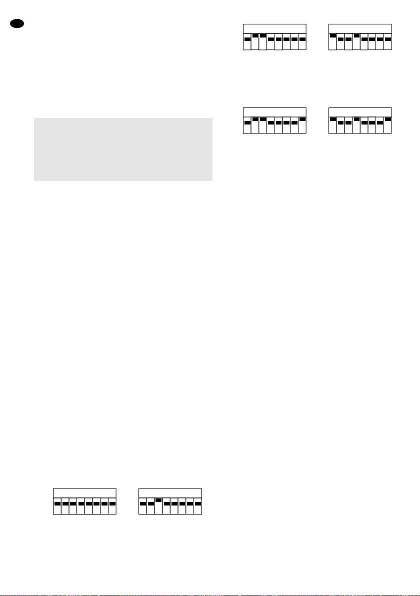
5 Montaje
Fije él aparato en el lugar deseado (soporte horizontal
de un pie de iluminación o barra transversal) con la
ayuda de dos soportes para proyectores o de dos tor-
nillos de montaje estables a través los trepadores de
montaje (5). El aparato puede también ser suspendido
a través de un trepador de montaje. En este caso fije
uno de los dos trepadores de montaje a los pernos
fileteados en el medio del aparato.
Para orientar el aparato, destornille las tuercas de
fijación(6), orientecomo deseadoy atornillelas tuercas.
6 Funcionamiento
Conecte el cable de red entregado que dispone de una
toma de alimentación hembra con la toma de alimenta-
ción (4) del aparato y la toma macho con una toma de
red 230V~/50Hz. El aparato está conectado cuando
la conexión de alimentación está efectuada. Una vez el
aparato bajo tensión, el espejo está colocado en una
posición de arranque definida, y el mando se reinicia-
liza. El aparato está listo para funcionar. Para des-
conectar el aparato, desconecte el cable de red.
Para una mejor utilización, le aconsejamos conec-
tar el aparato con una toma de red que podrá conec-
tarse y desconectarse a través de un interruptor de luz.
6.1 Gestión a través de la música
Para controlar el escáner a través del micro integrado,
ponga todos los 8 interruptores DIP de “Dipswitch A”
hacia abajo en la posición desconectada. Ponga el
interruptor 3 de “Dipswitch B” en la posición ON, y todos
los otros interruptores en la posición desconectada.
Regule, en la instalación audio, el volumen de ma-
nera que la dinámica de la música sea restituida de
manera óptima por los haces luminosos en movimiento.
6.1.1 Interconexión de varios escáneres
Es posible hacer funcionar juntos varios escáneres
para controlar todos los otros aparatos auxiliares
(Slave) con el mismo ritmo, a través del micro del apa-
rato principal (Master). 16 aparatos auxiliares como
máximo pueden controlarse por un aparato principal.
1) En el aparato principal (Master), ponga todos los
interruptores DIP como explicado en él capítulo 6.1.
➂Master con salida activada para un mando slave
2) En todos los aparatos auxiliares (Slave), ponga los
interruptores DIP como indicado seguidamente
(esquema 4).
➃Slave, mando micro a través de Master
Para el modo “Slave” con rotación invertida del
espejo, ponga, más a más, los dos interruptores
DIP 8 adicionalmente en “ON “:
➄Slave invertido, mando micro a través del Master
3) Conecte la salida (2) del aparato principal a través
de un cable XLR con la entrada (1) del primer apa-
rato auxiliar.
4) Conecte la salida del primer aparato auxiliar con la
entrada del segundo aparato auxiliar y seguida-
mente.
Consejo: después de cada modificación de los regla-
jes de los interruptores DIP, el escáner
debe arrancar de nuevo desconectándolo y
conectándolo.
6.2 Utilización a través de una unidad de control
El juego de luz LE-550DMX dispone de 5 canales
DMX que pueden controlar separadamente por una
unidad de control DMX512:
1. Canal 1 para el control de los modelos de colores
(gobos), parte Adel aparato
2. Canal 2 para ON/OFF de la lámpara, parte A del
aparato
3. Canal 3 para el control del sentido y de la velocidad
de rotación del espejo
4. Canal 4 para el control de los modelos de colores
(gobos), parte B del aparato
5. Canal 5 para ON/OFF de la lámpara, parte B del
aparato.
1) Conecte el escáner a través de la entrada (1) con la
unidad de control DMX512; a través de la salida
(2), es posible conectar otro juego de luz compa-
tible DMX512.
2) Regule los interruptores DIP de “Dipswitch A” con
la dirección que corresponde al canal de la unidad
de control DMX512, previsto para regular el canal 1
del juego de luz. Ponga los interruptores DIP de
“Dipswitch B” en la dirección que corresponde al
canal de la unidad de control DMX512 previsto
para controlar el canal 4 del aparato.
El reglaje de los interruptores DIP se efectúa de
manera binaria, es decir, que la dirección está atri-
buida según la potencia de 2:
El interruptor 1 corresponde a 20(=1), el inter-
ruptor 2 a 21(= 2), el interruptor 3 a 22(= 4) etc.
Las direcciones se regulan por “adición” de los
interruptores, p.ej. 4 + 16 + 32 = dirección 52. En
este caso, los interruptores 3, 5 y 6 deben estar en
12345678
O
N
Dipswitch B
12345678
O
N
Dipswitch A
12345678
O
N
Dipswitch B
12345678
O
N
Dipswitch A
12345678
O
N
Dipswitch B
12345678
O
N
Dipswitch A
¡Importante!
Para evitar toda acumulación de calor en el aparato,
el lugar de montaje debe ser elegido de manera que
durante el funcionamiento, la circulación de aire sea
suficiente. Las aperturas de ventilación de la caja no
deben en ningún caso estar obturadas (por cortinas
p.ej.).
E
20
This manual suits for next models
1
Table of contents
Languages:
Other IMG STAGE LINE Scanner manuals


