IMI 550 SERIES User manual

-1-
TECHNICAL MANUAL
for 550 SERIES CONDENSING UNITS
and 542 SERIES DUCTED CONDENSING UNITS
from IMI AIR CONDITIONING LTD
This manual provides technical and installation information for 550 series condensing units and 542 series ducted
condensing units.
INDEX PAGE
GENERAL
Specification details 2
Features and options 3
Part numbers 3
Dimensions and weights 4
SELECTION MCU / MCU+ performance data 5
DCUE performancedata 6
INSTALLATION MCU/ MCU+ 550 series 7
DCUE 542 series 9
Application, pipe sizing 11
Pipe connections 12
Electrical connections 12
Evacuating and charging 13
WIRING MCU14
DIAGRAMSMCU+ 15
DCUE 16
KITSPTC:1 phase units 17
CSR:1 phase MCU/ MCU+ 550 series 18
CSR: 1 phase DCUE 542 series 19
Head pressure control - 550 series MCUonly 20
Compressor jacket: MCU/ MCU+ 550 series 22
HP pressure switchesMCU / MCU+ 23
Isolator: DCUE 542 series 25
3 minute timer: 550 series MCUonly 27
Wall mounting MCU/ MCU+ 550 series 28
Wall mounting: DCUE 542 series 30
Overload: MCU/ MCU+ 1 phase 550 series 31
Overload: DCUE 1 phase 542 series 32
Volt free relay 33
Duct: DCUE 542 series 34
Plenum: DCUE 542 series 34
Grille: DCUE 542 series 36
COMPONENT Exploded views of units with 37
IDENTIFICATIONcomponent identification
IMI Air Conditioning Ltd.
Armytage Road, Brighouse,
West Yorkshire. HD6 1QF
Tel: (01484) 405600
Fax: (01484) 405620 Asubsidiarycompany of IMI plc
55008275-03
Heronhill - for all your IMI requirements
Tel: 01823 665660
www.heronhill.co.uk
Fax: 01823 665807

-2-
IMI AIR CONDITIONING LIMITED - CONDENSING UNITS
SPECIFICATION DETAILS
MCU(+) SIZE 15 20 30 40 50 60 80 90 100 130 150 165 180 200
Nominal cooling capacity ¶ kW 2.5 2.8 3.7 4.2 5.8 7.0 7.4 8.2 10.9 12.4 13.9 14.7 17.1 19.9
R22 Compressor - 1 Ph (230V 50Hz)
Power(nominal) kW0.71.01.21.41.92.32.94.0------
StartingcurrentLRA A21243232586176114------
NominalcurrentFLA A4.15.25.978.59.91116.2------
R22 Compressor - 3 Ph (400V 50Hz)
Power (nominal) kW - - 1.6 2.0 1.9 2.3 2.8 4.0 4.0 4.3 5.2 5.8 6.8 8.9
StartingcurrentLRA A/Ph- - 182226324048516268717198
Nominal current FLA A/Ph - - 3.9 5.1 4.0 4.1 4.5 7.0 7.1 7.6 8.6 9.5 11.6 16.1
R22 charge supplied g 630 980 950 1180 1610 1900 1800 1960 2400 3970 3970 4320 4420 5220
Operating weight kg 1Ph45(39*)46(40*)48(41*)53(45*)64656676------
3 Ph - - 48 53 62 63 64 73 81 101 103 103 118 173
*Obsolete units fitted with a rotary compressor
R407C Compressor - 1 Ph (230V 50Hz)
Power(nominal) kW1.11.61.62.12.02.43.04.2------
StartingcurrentLRA A23283650586176114------
NominalcurrentFLA A5.96.98.110.28.99.811.516.9------
R407C Compressor - 3 Ph (400V 50Hz)
Power (nominal) kW - - 1.6 2.0 1.9 2.4 3.0 4.1 4.3 4.4 5.3 6.0 7.0 9.4
StartingcurrentLRA A/Ph- - 182226324048516268717198
Nominal current FLA A/Ph - - 3.6 4.8 4.2 4.2 4.9 7.1 7.2 7.7 8.7 9.5 11.9 16.9
R407C charge supplied g 660 1030 1000 1240 1690 2000 1880 2060 2520 4170 4170 4540 4640 5480
Operating weight kg 1Ph4546485364656676------
3 Ph - - 48 53 62 63 64 73 81 101 103 103 118 173
Connection sizes
Suction ins odf 3/8 3/8 1/2 1/2 1/2 5/8 5/8 5/8 3/4 3/4 3/4 3/4 7/8 7/8
Liquid ins odf 3/8 3/8 3/8 3/8 3/8 3/8 1/2 1/2 1/2 1/2 1/2 1/2 1/2 1/2
Sound Pressure Levels (SPL) at 3m distance in free field conditions. (Reference 2 x 10⁻⁵ N/m²)
Fan speed min dBA4546475051515153545656575656
NC 40 41 42 47 47 46 45 47 48 49 49 51 50 50
Fan speed max dBA5050515354545856606056606161
NC 46 47 48 50 50 50 56 53 56 54 49 55 60 60
MCU(+) SIZE 15 20 30 40 50 60 80 90 100 130 150 165 180 200
Condenser fan (1Ph 230V 50Hz)
Airflow (max speed) m³/s 0.813 0.813 0.813 0.723 0.783 0.783 0.783 1.140 1.140 1.740 1.740 1.740 2.407 2.407
Fan motor rating kW 0.13 0.13 0.13 0.13 0.13 0.13 0.13 0.24 0.24 2 x 0.13 2 x 0.13 2 x 0.13 2 x 0.24 2 x 0.24
Nominal current FLA A 0.6 0.6 0.6 0.6 0.6 0.6 0.6 1.0 1.0 2 x 0.60 2 x 0.60 2 x 0.60 2 x 1.00 2 x 1.00
Fans:- No. x diameter # x mm 1 x 457 1 x 457 1 x 457 1 x 457 1 x 457 1 x 457 1 x 457 1 x 508 2 x 457 2 x 457 2 457 2 x 457 2 x 508 2 x 508
Fans:- max speed r.p.m. 760 760 760 760 910 910 910 950 950 910 910 910 950 950
DCUE SIZE10(Obs)15203040506080
Nominal cooling capacity ¶ kW 2.0 2.6 2.8 3.7 4.6 5.8 6.3 6.9
Compressor - 1 Ph (230V 50Hz)
Power (nominal) kW 0.75 1.00 1.16 1.46 1.87 2.20 2.56 2.95
Starting current LRA A 16 23 28 36 50 51 60 71
Nominal current FLA A 3.4 5.2 5.9 7.2 9.3 10.0 12.0 14.1
Compressor - 3 Ph (400V 50Hz)
Power (nominal) kW - - - 1.45 1.90 2.12 2.52 2.80
Starting current LRA A/Ph - - - 18 22 24 24 27
Nominal current FLA A/Ph - - - 2.7 3.9 4.0 4.2 4.8
Crankcase heater A 0.25 0.25 0.25 0.25 0.25 0.25 0.25 0.25
R22 charge supplied g 540 570 880 930 990 1250 1140 1400
R407C charge supplied g 570 600 930 990 1050 1240 1190 1480
Connection sizes
Suction ins odf 3/8 3/8 3/8 1/2 1/2 1/2 5/8 5/8
Liquid ins odf 3/8 3/8 3/8 3/8 3/8 3/8 3/8 1/2
DCUE SIZE10(Obs)15203040506080
Condenser fan (1 Ph 230V 50Hz)
Airflow (max speed) m³/s 0.44 0.44 0.44 0.42 0.38 0.53 0.53 0.48
Max external resistance Pa 100 100 100 100 100 100 100 100
Fan motor rating kW 0.34 0.34 0.34 0.34 0.34 0.34 0.34 0.34
Starting current A 6.0 6.0 6.0 6.0 6.0 6.0 6.0 6.0
Nominal current FLA A 2.6 2.6 2.6 2.6 2.6 2.6 2.6 2.6
Operating weight kg 66 69 70 70 72 81 81 84
Sound Pressure Levels (SPL) at 3m distance from unit in ceiling void. (Reference 2 x 10⁻⁵ N/m²)
Fan speed min dBA3535353535444444
NC 28 28 28 28 28 31 31 31
Fan speed max dBA5252525252545454
NC 46 46 46 46 46 48 48 48
¶ Nominal capacities quoted at 7.5/C saturated suction temperature and 35/C air onto the condenser.
Heronhill - for all your IMI requirements
Tel: 01823 665660
www.heronhill.co.uk
Fax: 01823 665807

-3-
STANDARD FEATURES AND OPTIONS
MCU = standard condensing unit MCU+ = standard condensing unit + head pressure control + low pressure switch
DCUE = electronic controlled ducted condensing unit + head pressure control + HP and LP switches
CONDENSING UNIT MODEL MCU MCU+ DCUE
Easy access for installation and service 99 9
Suction and liquid service valves 99 9
Expansion device (orifice type) 99 9
Pre-charged with refrigerant (R22 or R407C) 99 9
Heat pump version available 99 9
Ducted air inlet and/or discharge -- -- 9
Ceiling suspendable -- -- 9
Capacitor start relay (1phase) (MCU(+) 15 - 40, ALL DCUE) * * *
PTC resistor (1 phase) * * *
Head pressure control * 99
LP cut-out * 99
HP cut-out auto (DCUE has manual backup) * 99
Isolator * * *
3 minute start time delay * 99
Wall mounting brackets * * *
Contactor 99 9
Overload (standard on 3ph) * -- *
Low ambient start -- -- 9
9= Standard Feature, * = Option
PART NUMBERS
MCU/MCU+ CONDENSING UNITS
MCU 1Ph
Rotary (Obs) MCU 15 MCU 20 MCU 30 MCU 40 MCU 1Ph
Recip MCU 15 MCU 20 MCU 30 MCU 40
R407C -- -- -- -- R407C 55022045 55022046 55022047 55022048
R22 55099066 55099067 55099068 55099069 R22 55022151 55022152 55022153 55022154
MCU 1Ph
Scroll MCU 50 MCU 60 MCU 80 MCU 90 MCU 3Ph
Recip MCU 30 MCU 40
R407C 55099049 55099050 55099051 55099052 R407C 55022053 55022054
R22 55022070 55022071 55022072 55022073 R22 55022074 55022075
MCU 3Ph
Scroll MCU 50 MCU 60 MCU 80 MCU 90 MCU 100 MCU 130 MCU 150 MCU 165 MCU 180 MCU 200
R407C 55022055 55022056 55022057 55022058 55022059 55022060 55022061 55022062 55022063 55022064
R22 55022076 55022077 55022078 55022079 55022080 55022081 55022082 55022083 55022084 55022085
MCU+ 1Ph
Rotary (Obs) MCU+ 15 MCU+ 20 MCU+ 30 MCU+ 40 MCU+ 1Ph
Recip MCU+ 15 MCU+ 20 MCU+ 30 MCU+ 40
R407C -- -- -- -- R407C 55022002 55022003 55022004 55022005
R22 55099024 55099025 55099026 55099027 R22 55022155 55022156 55022157 55022158
MCU+ 1Ph
Scroll MCU+ 50 MCU+ 60 MCU+ 80 MCU+ 90 MCU+ 3Ph
Recip MCU+ 30 MCU+ 40
R407C 55022006 55022007 55022008 55022009 R407C 55022011 55022012
R22 55022028 55022029 55022030 55022031 R22 55022032 55022033
MCU+ 3Ph
Scroll MCU+ 50 MCU+ 60 MCU+ 80 MCU+ 90 MCU+ 100 MCU+ 130 MCU+ 150 MCU+ 165 MCU+ 180 MCU+ 200
R407C 55022013 55022014 55022015 55022016 55022017 55022018 55022019 55022020 55022021 55022022
R22 55022034 55022035 55022036 55022037 55022038 55022039 55022040 55022041 55022042 55022043
Part numbers shown in
underlined italics
eg
55099066
are obsolete models, shown in this manual for reference only
DCUE DUCTED CONDENSING UNITS (542 Series, reciprocating compressors)
Electronic DCUE DCUE 10 (Obs) DCUE 15 DCUE 20 DCUE 30 DCUE 40 DCUE 50 DCUE 60 DCUE 80
R22 54200001 542000 542000 542000 542000 542000 542000 542000
R407C 54200026 542000 542000 542000 542000 542000 542000 542000
Electronic DCUE 3Ph -- -- -- DCUE 30 DCUE 40 DCUE 50 DCUE 60 DCUE 80
R22 -- -- -- 542000 542000 542000 542000 542000
R407C -- -- -- 542000 542000 542000 542000 542000
Heronhill - for all your IMI requirements
Tel: 01823 665660
www.heronhill.co.uk
Fax: 01823 665807

-4-
UNPACKED DIMENSIONS and WEIGHTS
MCU / MCU+ CONDENSING UNITS
Model 15 20 30 40 50 60 80 90 100 130 150 165 180 200
HEIGHT mm 620 620 620 620 720 720 720 820 820 1080 1080 1080 1275 1275
WIDTH mm 900 900 900 900 1000 1000 1000 1000 1000 1000 1000 1000 1100 1100
DEPTH mm 300 300 300 300 300 300 300 350 350 425 425 425 425 425
1 Ph kg 45(39*)46(40*)48(41*)53(45*)64656676------
3 Ph kg - - 48 53 62 63 64 73 81 101 103 103 118 173
* Obsolete R407C Models and R22 models fitted with a rotary compressor
DCUE DUCTED CONDENSING UNITS
Model DCUE 10 (Obs) DCUE 15 DCUE 20 DCUE 30 DCUE 40 DCUE 50 DCUE 60 DCUE 80
HEIGHT mm 560 560 560 560 560 625 625 625
WIDTH mm 1075 1075 1075 1075 1075 1245 1245 1245
DEPTH mm 565 565 565 565 565 565 565 565
WEIGHT kg 66 69 70 70 72 81 81 84
PACKED DIMENSIONS and WEIGHTS
MCU / MCU+ CONDENSING UNITS
Model 15 20 30 40 50 60 80 90 100 130 150 165 180 200
HEIGHT mm 620 620 620 620 720 720 720 820 820 1080 1080 1080 1280 1280
WIDTH mm 980 980 980 980 1080 1080 1080 1090 1090 1090 1090 1090 1215 1215
DEPTH mm 340 340 340 340 340 340 340 390 390 465 465 465 465 465
1 Ph kg 47(41*)48(42*)50(43*)55(47*)66676878------
3 Ph kg - - 50 55 64 65 66 75 83 105 107 107 123 178
* Obsolete R407C Models and R22 models fitted with a rotary compressor
DCUE DUCTED CONDENSING UNITS
Model DCUE 10 (Obs) DCUE 15 DCUE 20 DCUE 30 DCUE 40 DCUE 50 DCUE 60 DCUE 80
HEIGHT mm 580 580 580 580 580 650 650 650
WIDTH mm 1090 1090 1090 1090 1090 1270 1270 1270
DEPTH mm 610 610 610 610 610 610 610 610
WEIGHT kg 71 74 75 76 76 86 86 90
Heronhill - for all your IMI requirements
Tel: 01823 665660
www.heronhill.co.uk
Fax: 01823 665807

-5-
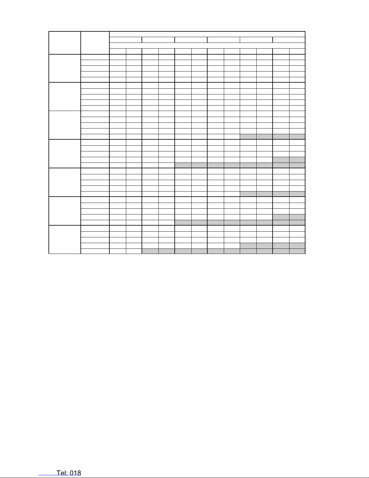
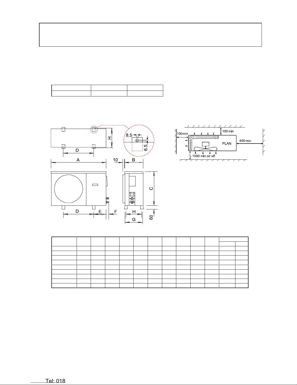
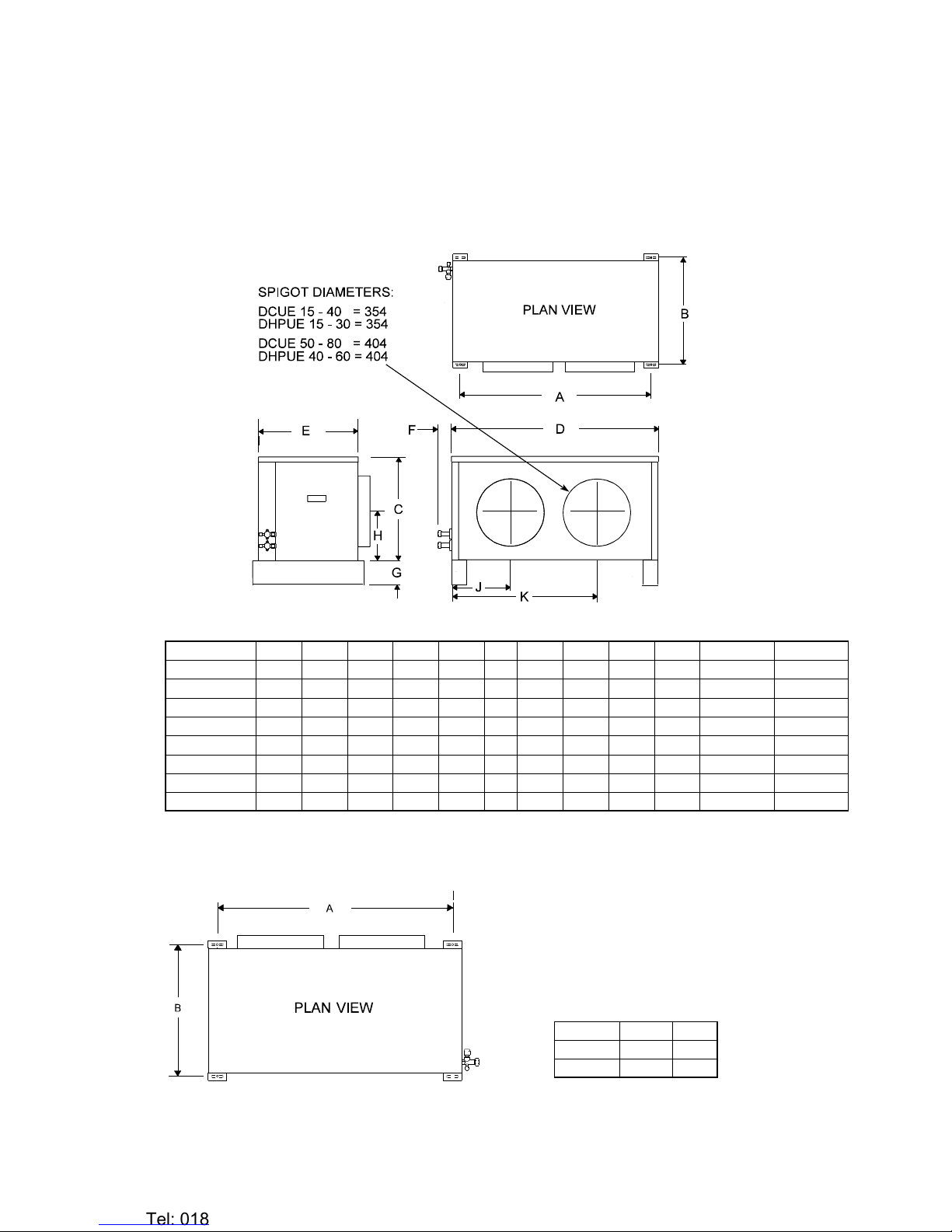
MCU(+) 15 - 200 CONDENSING UNIT CAPACITIES
MODEL
Air on to
Condenser
/C
Saturated Suction Temperature /C
-2.502.557.510
Cooling capacity and power input kW
Cap. Power Cap. Power Cap. Power Cap. Power Cap. Power Cap. Power
MCU(+) 15
25 1.93 0.69 2.14 0.70 2.35 0.70 2.55 0.71 2.76 0.72 2.96 0.72
30 1.81 0.74 2.01 0.75 2.21 0.76 2.41 0.77 2.61 0.78 2.81 0.79
35 1.69 0.79 1.89 0.80 2.08 0.81 2.27 0.83 2.46 0.84 2.65 0.86
40 1.58 0.84 1.76 0.86 1.95 0.88 2.13 0.90 2.32 0.91 2.50 0.93
45 1.46 0.90 1.64 0.92 1.82 0.94 2.00 0.97 2.18 0.99 2.36 1.01
MCU(+) 20
25 2.25 0.80 2.49 0.81 2.71 0.81 2.96 0.82 3.22 0.84 3.49 0.85
30 2.08 0.84 2.31 0.86 2.54 0.87 2.78 0.89 3.01 0.90 3.26 0.92
35 1.94 0.90 2.16 0.92 2.38 0.93 2.61 0.95 2.84 0.97 3.05 0.98
40 1.83 0.98 2.04 0.99 2.25 1.01 2.46 1.03 2.66 1.05 2.86 1.06
45 1.73 1.07 1.92 1.08 2.11 1.09 2.30 1.11 2.49 1.13 2.68 1.15
MCU(+) 30
25 2.87 1.02 3.22 1.05 3.53 1.06 3.74 1.04 4.12 1.07 4.49 1.10
30 2.71 1.10 3.06 1.13 3.27 1.12 3.51 1.12 3.84 1.15 4.19 1.18
35 2.59 1.20 2.82 1.20 3.03 1.19 3.36 1.23 3.68 1.26 3.79 1.22
40 2.38 1.27 2.71 1.32 2.80 1.26 3.12 1.31 3.32 1.31 3.62 1.35
45 2.11 1.30 2.43 1.36 2.53 1.31 2.84 1.37
MCU(+) 40
25 3.38 1.13 3.70 1.15 4.02 1.16 4.35 1.18 4.67 1.19 5.00 1.21
30 3.19 1.22 3.50 1.24 3.81 1.26 4.11 1.28 4.42 1.30 4.73 1.32
35 3.01 1.31 3.30 1.33 3.59 1.36 3.88 1.38 4.17 1.41 4.46 1.43
40 2.84 1.40 3.11 1.43 3.37 1.47 3.63 1.50 3.89 1.53 4.15 1.56
45 2.68 1.51 2.91 1.55 3.15 1.58 3.38 1.62 3.61 1.66 3.85 1.70
MCU(+) 50
25 4.57 1.87 5.09 2.03 5.51 2.14 5.97 2.25 6.41 2.38 6.79 2.51
30 4.34 1.95 4.75 2.09 5.25 2.19 5.63 2.32 6.04 2.45 6.49 2.58
35 3.94 2.00 4.42 2.13 4.91 2.24 5.29 2.36 5.75 2.49 6.09 2.65
40 3.76 2.05 4.22 2.18 4.58 2.29 5.04 2.41 5.39 2.58 5.69 2.74
45 3.50 2.12 3.93 2.22 4.37 2.35 4.69 2.48
MCU(+) 60
25 5.43 2.22 6.02 2.27 6.61 2.31 7.21 2.37 7.80 2.42 8.39 2.47
30 5.06 2.46 5.64 2.51 6.22 2.56 6.80 2.62 7.39 2.67 7.97 2.73
35 4.77 2.72 5.33 2.78 5.89 2.83 6.45 2.89 7.01 2.95 7.57 3.01
40 4.39 3.01 4.91 3.07 5.43 3.13 5.95 3.19 6.47 3.26 6.99 3.32
45 4.02 3.32 4.49 3.40 4.97 3.46 5.45 3.53 5.93 3.60
MCU(+) 80
25 6.07 2.26 6.64 2.31 7.21 2.37 7.79 2.42 8.36 2.47 8.93 2.53
30 5.68 2.49 6.23 2.54 6.77 2.60 7.32 2.66 7.87 2.71 8.42 2.77
35 5.28 2.72 5.81 2.78 6.33 2.83 6.86 2.89 7.38 2.95 7.91 3.01
40 4.90 3.03 5.39 3.10 5.88 3.16 6.37 3.23 6.86 3.29 7.35 3.36
45 4.52 3.35 4.97 3.42 5.43 3.49 5.88 3.56 6.33 3.63
MCU(+) 90
25 7.16 2.89 7.71 2.95 8.26 3.01 8.81 3.06 9.36 3.12 9.91 3.18
30 6.69 3.17 7.21 3.24 7.74 3.30 8.27 3.36 8.79 3.42 9.32 3.48
35 6.22 3.46 6.72 3.52 7.22 3.59 7.72 3.65 8.23 3.72 8.73 3.78
40 5.80 3.79 6.27 3.86 6.74 3.93 7.22 4.00 7.69 4.07 8.17 4.14
45 5.38 4.12 5.82 4.20 6.27 4.27 6.71 4.34 7.16 4.42 7.60 4.49
MCU(+) 100
25 7.87 3.18 9.10 3.42 10.40 3.66 11.52 3.87 12.61 3.87 13.83 3.86
30 7.60 3.23 8.73 3.88 9.68 3.81 10.71 4.05 11.66 4.18 12.71 4.29
35 7.00 3.24 8.06 3.56 9.03 3.87 9.92 4.13 10.91 4.31 11.89 4.52
40 6.17 3.16 7.12 3.54 8.14 3.86 8.91 4.17 9.86 4.47 10.80 4.75
45 5.12 2.95 6.18 3.47 7.07 3.89 7.98 4.25
MCU(+) 130
25 9.69 3.14 10.71 3.46 11.72 3.73 12.76 4.01 13.71 4.28 14.56 4.54
30 9.09 3.16 10.07 3.46 11.11 3.74 12.12 4.08 13.05 4.36 13.93 4.68
35 8.27 3.27 9.32 3.61 10.27 3.91 11.34 4.25 12.41 4.56 13.29 4.91
40 7.61 3.29 8.58 3.65 9.54 4.01 10.44 4.31 11.46 4.68
45 6.89 3.34 7.63 3.68 8.68 4.09
MCU(+) 150
25 11.06 3.73 12.26 4.13 13.26 4.46 14.30 4.82 15.24 5.15 16.19 5.47
30 10.42 3.75 11.52 4.14 12.56 4.48 13.57 4.88 14.56 5.24 15.48 5.63
35 9.46 3.89 10.59 4.32 11.61 4.68 12.69 5.08 13.77 5.47 14.77 5.90
40 8.70 3.90 9.79 4.35 10.76 4.78 11.67 5.15
45 7.90 3.98 8.89 4.40
MCU(+) 165
25 11.97 4.13 13.30 4.57 14.29 4.95 15.32 5.36 16.26 5.73 17.28 6.09
30 11.31 4.15 12.49 4.59 13.52 4.98 14.54 5.42 15.57 5.82 16.51 6.26
35 10.26 4.30 11.44 4.79 12.51 5.19 13.59 5.64 14.67 6.08 15.75 6.56
40 9.43 4.31 10.60 4.81 11.58 5.29 12.49 5.71
45 8.57 4.41
MCU(+) 180
25 13.42 4.71 14.97 5.12 16.28 5.45 17.63 5.79 18.86 6.13 20.27 6.47
30 12.74 4.75 14.13 5.16 15.39 5.51 16.76 5.90 18.08 6.26 19.34 6.64
35 11.52 4.94 12.94 5.38 14.34 5.76 15.67 6.16 17.12 6.56 18.51 6.98
40 10.63 4.96 11.97 5.44 13.28 5.89 14.43 6.26 15.95 6.74 17.31 7.18
45 9.72 5.10 10.95 5.61 12.17 6.09 13.31 6.49 14.63 6.98
MCU(+) 200
25 15.28 5.37 16.96 5.90 18.96 6.47 21.12 6.87 22.34 7.28 23.48 7.65
30 14.42 5.41 16.01 5.92 17.73 6.41 19.75 6.96 21.18 7.40 22.52 7.88
35 13.13 5.51 14.68 6.17 16.49 6.68 18.30 7.23 19.88 7.74 21.48 8.27
40 12.03 5.62 13.59 6.24 15.13 6.82 16.58 7.31 18.33 7.92
45 10.99 5.78 12.36 6.42 13.80 7.03
Note: Operation in the shaded areas of the tables will result in unacceptably high condensing temperatures and should be avoided.
Heronhill - for all your IMI requirements
Tel: 01823 665660
www.heronhill.co.uk
Fax: 01823 665807

-6-
DCUE 15 - 80 CONDENSING UNIT CAPACITIES
MODEL
Air on to
Condenser
/C
Saturated Suction Temperature /C
-2.5 0 2.5 5 7.5 10
Cooling capacity and power input kW
Cap. Power Cap. Power Cap. Power Cap. Power Cap. Power Cap. Power
DCUE 15
25 1.88 0.97 2.12 1.03 2.35 1.08 2.61 1.13 2.87 1.16 3.21 1.19
30 1.71 1.00 1.94 1.07 2.17 1.11 2.43 1.17 2.74 1.21 2.98 1.25
35 1.67 1.05 1.88 1.12 2.02 1.17 2.33 1.23 2.55 1.27 2.68 1.32
40 1.47 1.07 1.74 1.16 1.87 1.21 2.17 1.26 2.37 1.32 2.57 1.35
45 1.45 1.10 1.63 1.19 1.83 1.27 2.01 1.32 2.29 1.35 2.38 1.41
DCUE 20
25 2.25 1.19 2.49 1.26 2.71 1.30 2.96 1.35 3.22 1.41 3.49 1.46
30 2.08 1.22 2.31 1.28 2.54 1.34 2.78 1.40 3.01 1.45 3.26 1.51
35 1.94 1.26 2.16 1.33 2.38 1.40 2.61 1.46 2.84 1.52 3.05 1.58
40 1.83 1.30 2.04 1.37 2.25 1.44 2.46 1.50 2.66 1.56 2.86 1.63
45 1.73 1.34 1.92 1.43 2.11 1.50 2.30 1.56 2.49 1.62 2.68 1.69
DCUE 30
25 2.87 1.44 3.22 1.52 3.53 1.59 3.74 1.65 4.12 1.72 4.49 1.75
30 2.71 1.48 3.06 1.57 3.27 1.63 3.51 1.70 3.84 1.77 4.19 1.82
35 2.59 1.55 2.82 1.62 3.03 1.70 3.36 1.77 3.68 1.85 3.79 1.92
40 2.38 1.59 2.71 1.67 2.80 1.75 3.12 1.82 3.32 1.90 3.62 1.97
45 2.11 1.65 2.43 1.73 2.53 1.83 2.84 1.91
DCUE 40
25 3.81 1.80 4.23 1.91 4.46 2.01 4.75 2.07 5.09 2.17 5.47 2.26
30 3.56 1.87 3.97 1.97 4.27 2.04 4.57 2.13 4.79 2.23 5.16 2.32
35 3.27 1.91 3.63 2.00 3.93 2.09 4.32 2.17 4.59 2.27 4.83 2.37
40 3.17 1.96 3.41 2.05 3.31 2.13 4.03 2.22 4.28 2.34
45 2.98 2.02 3.20 2.09
DCUE 50
25 4.57 1.87 5.09 2.03 5.51 2.14 5.97 2.25 6.41 2.38 6.79 2.51
30 4.34 1.95 4.75 2.09 5.25 2.19 5.63 2.32 6.04 2.45 6.49 2.58
35 3.94 2.00 4.42 2.13 4.91 2.24 5.29 2.36 5.75 2.49 6.09 5.65
40 3.76 2.05 4.22 2.18 4.58 2.29 5.04 2.41 5.39 2.58 5.69 2.74
45 3.50 2.12 3.93 2.22 4.37 2.35 4.69 2.48
DCUE 60
25 4.96 2.28 5.48 2.44 5.99 2.58 6.45 2.72 6.97 2.84 7.46 2.96
30 4.62 2.37 5.10 2.52 5.64 2.64 6.11 2.78 6.62 2.91 7.07 3.04
35 4.33 2.42 4.81 2.56 5.30 2.70 5.79 2.84 6.25 2.97 6.67 3.12
40 4.06 2.48 4.52 2.62 4.98 2.76 5.44 2.89 5.88 3.07
45 3.81 2.56 4.24 2.67
DCUE 80
25 5.90 2.68 6.44 2.88 6.84 3.05 7.31 3.18 7.73 3.33 8.21 3.47
30 5.49 2.78 6.01 2.97 6.51 3.10 6.99 3.26 7.38 3.41 7.82 3.56
35 5.09 2.85 5.60 3.02 6.09 3.17 6.57 3.32 6.93 3.47 7.35 3.64
40 4.76 2.92 5.32 3.08 5.68 3.23 6.15 3.38
45 4.54 3.00
Note: Operation in the shaded areas of the tables will result in unacceptably high condensing temperatures and should be avoided.
Heronhill - for all your IMI requirements
Tel: 01823 665660
www.heronhill.co.uk
Fax: 01823 665807

-7-
INSTALLATION of 550 Series CONDENSING UNITS
These outdoor units are supplied fitted with an expansion device which contains a restrictor to control
refrigerant flow.
For use in systems which have their own refrigerant control at the indoor unit (eg. a capillary), remove
and discard the expansion device connected to the condensing unit prior to installation.
Note: It is easier to fit kits prior to mounting the unit.
These units are designed to stand on a flat surface. If the unit is to be wall mounted the
following kits are available.
(IMI Air Conditioning cannot accept liability for installers own mounting arrangements).
Model MCU(+) 15 - 80 MCU(+) 90 - 200
Mounting Bracket Kit 55021100 55021101
Whether floor or wall mounted, it is essential that the mounting surface is capable of
supporting the unit weight. Leave space around the unit for air circulation and access for installation and maintenance.
MOUNTING: MCU(+) 15 - 100
Dimensions in mm.
MODELABCDEFGHJK
Weight (kg)
1 Ph 3 Ph
MCU(+) 15 900 300 560 525 185 60 333 308 290 260 45 (39*) --
MCU(+) 20 900 300 560 525 185 60 333 308 290 260 46 (40*) --
MCU(+) 30 900 300 560 525 185 60 333 308 290 260 48 (41*) 48
MCU(+) 40 900 300 560 525 185 60 333 308 290 260 53 (45*) 53
MCU(+) 50 1000 300 660 570 213 60 333 308 290 260 64 62
MCU(+) 60 1000 300 660 570 213 60 333 308 290 260 65 63
MCU(+) 80 1000 300 660 570 213 60 333 308 290 260 66 64
MCU(+) 90 1000 350 760 495 250 70 383 358 340 310 76 73
MCU(+) 100 1000 350 760 495 250 70 383 358 340 310 -- 81
*Obsolete R407C and R22 models fitted with a rotary compressor
Heronhill - for all your IMI requirements
Tel: 01823 665660
www.heronhill.co.uk
Fax: 01823 665807

-8-
MOUNTING: MCU(+) 130 - 200
Dimensions in mm.
MODEL A B C D E F G H J K Weight (kg)
MCU(+) 130 1000 425 1020 495 251 100 458 433 415 385 101
MCU(+) 150 1000 425 1020 495 251 100 458 433 415 385 103
MCU(+) 165 1000 425 1020 495 251 100 458 433 415 385 103
MCU(+) 180 1100 425 1215 675 211 95 458 433 415 385 118
MCU(+) 200 1100 425 1215 675 211 95 458 433 415 385 173
--o--o--O--O--O--o--o--
Heronhill - for all your IMI requirements
Tel: 01823 665660
www.heronhill.co.uk
Fax: 01823 665807

-9-
INSTALLING 542 SERIES DUCTED CONDENSING UNITS
MOUNTING
Units are supplied with a polystyrene packing piece supporting the blower assembly, this MUST be removed prior to
commissioning.
Ducted Units are designed to be hung on a wall (kit available), suspended from a ceiling (installer supplied fittings), or to
stand on a flat surface. Whichever method is used it is essential that the mounting surface is capable of supporting the units
weight.
DIMENSIONS
Model A B C D E F G H J K Spigot dia. Weight (kg)
DCUE 10 (Obs) 930 510 495 1004 490 65 65 210 317 717 354 66
DCUE 15 930 510 495 1004 490 65 65 210 317 717 354 69
DCUE 20 930 510 495 1004 490 65 65 210 317 717 354 70
DCUE 30 930 510 495 1004 490 65 65 210 317 717 354 70
DCUE 40 930 510 495 1004 490 65 65 210 317 717 354 72
DCUE 50 1100 510 560 1174 490 65 65 240 392 865 404 81
DCUE 60 1100 510 560 1174 490 65 65 240 392 865 404 81
DCUE 80 1100 510 560 1174 490 65 65 240 392 865 404 84
FLOOR MOUNTING
Using the appropriate side of the packing carton as a
template, (centres marked A), mark out and drill 4 holes
to suit maximum M8 bolts (also see opposite). Secure the
unit to the floor. Discard the stabilizing brackets.
Dimensions in mm.
Model A B
10 to 40 930 510
50 to 80 1100 510
Heronhill - for all your IMI requirements
Tel: 01823 665660
www.heronhill.co.uk
Fax: 01823 665807

-10-
SUSPENSION MOUNTING
The installer must supply 4 x M8 threaded rods with 16 nuts and washers to suit.
IMPORTANT: The stabilizing brackets provided MUST be used when suspending a unit.
Fit the stabilizing brackets to the top corners of the backpanel and front face using the No. 10 screws
provided, (2 per bracket).
If these brackets are omitted the unit will be subject to unacceptable movement on compressor start.
Where long drops of M8 rod are used, it is advisable to incorporate
flexible pipes in the suction and expansion lines to absorb any
movement of the unit.
Using the template printed on the side of the packing carton,
(centres marked A), mark out the ceiling and drill 4 holes to suit M8
screwed rod.
Raise the unit to the required height and pass the screwed rods
through the mounting holes in the units feet and stabilizing
brackets.
Secure the unit with a nut and washer on either side of each
stabilizing bracket and two nuts and washers underneath each foot
mounting hole, (as shown).
WALL MOUNTING
Wall mounting brackets are available as an optional kit (53200407).
DUCTWORK
Each unit is supplied with air inlet and discharge spigots:-
Models 10 to 40 - 354mm (14") dia.: Models 50 to 80 - 404mm (16") dia.
These may be used for connecting installers ducting or used with the optional duct, plenum and grille kits.
Refer to the kit instruction for installation methods.
The front face of the units are also fitted with M6 rivnuts to accept installer supplied square ducting, see dimensions below.
Maximum flange width is 25mm and fixing holes should be central within them.
NOTE: It is essential that ducting is adequately insulated to prevent sweating. An insulation thickness of at least 45mm
is recommended.
Dimensions
mm.
Model
10 to 40 50 to 80
A400 450
B300 350
C100 100
--o--o--O--O--O--o--o--
Heronhill - for all your IMI requirements
Tel: 01823 665660
www.heronhill.co.uk
Fax: 01823 665807

-11-
APPLICATION
These outdoor units are supplied fitted with an expansion device which contains a restrictor to control refrigerant flow.
For use in systems which have refrigerant control at the indoor unit, remove and discard the expansion device
connected to the condensing unit prior to installation.
1To maximise performance, pipe runs should be kept as short as possible, avoiding sharp bends. However, individual
pipe runs to a maximum of 45m (80m when the expansion device is retained) on air conditioners, are permissible
provided good refrigeration practice is followed (except for obsolete 1 Ph models with rotary compressors, i.e.,
up to and including size 40, which have a maximum run of 15m).
Published performance duties are based on 7.5m pipe runs. Correctly sized pipes for each installation will result in
no significant loss of capacity on extended pipe runs.
a) Pipe sizes are based on:-
Minimum of 3.8 m/s (750 fpm) suction gas velocity for horizontal or downflow.
Minimum of 7.6 m/s (1500 fpm) suction gas velocity for upflow.
Maximum of 15.2 m/s (3000 fpm) suction gas.
b) Where vertical risers exceed 3m, oil traps must be formed in the pipe. This will help ensure that oil returns to
the compressor. Typically fit an oil trap every 3m with a trap at the bottom of the riser.
2Add 25 grams of refrigerant oil (polyolester oil for all units except those fitted with rotary compressors which contain
PVE oil and need no extra) for every 350 grams of charge added to systems with pipe runs exceeding 25m, up to a
maximum of 300 grams; preferably by slowly pumping into the suction side with the unit running, after charging the
system.
3For systems with refrigerant control at the indoor OR outdoor unit ; the table below shows the suggested pipe sizes
(in inches) and equivalent lengths.
WITH EXPANSION DEVICE AT THE MCU(+) WITH INDOOR REFRIGERANT CONTROL
MAXIMUM EQUIVALENT LENGTH
OF SUCTION LINE
PIPES (m)
EXPANSION
LINE PIPE
SIZES
MAXIMUM EQUVALENT LENGTH OF SUCTION
LINE PIPES (m) LIQUID LINE PIPE
SIZES
HORIZONTAL OR DOWNFLOW UPFLOW
UNIT 3/8 1/2 5/8 3/4 7/8 1-1/8 1-3/8 3/8 1/2 5/8 3/8 1/2 5/8 3/4 7/8 1-1/8 1-3/8 MAX. 15m 1/4 3/8 1/2 5/8
MCU(+) 15* 7.5 50 50 8 21 3/8 21
MCU(+) 20* 50 50 8 21 3/8 21
MCU(+) 30* 12 40 80 50 80 8 45 1/2 21 45
MCU(+) 40* 82580 7.580 82345 1/2 45
MCU(+) 50 18 50 80 7.5 50 80 8 15 45 5/8 21 45
MCU(+) 60 15 45 80 7.5 50 80 7.5 21 45 5/8 21 45
MCU(+) 80 12 35 80 7.5 50 80 7.5 21 45 5/8 21 45
MCU(+) 90 7.5 20 40 80 7.5 80 7.5 21 45 5/8 21 45
MCU(+) 100 15 30 80 7.5 80 7.5 21 45 3/4 21 45
MCU(+) 130 10 20 80 7.5 80 7.5 21 45 3/4 21 45
MCU(+) 150 10 20 80 7.5 80 7.5 21 45 3/4 21 45
MCU(+) 165 7.5 15 50 80 7.5 80 8 21 45 3/4 21 45
MCU(+) 180 7.5 15 50 80 7.5 80 8 21 45 1-1/8 21 45
MCU(+) 200 7.5 15 50 80 7.5 80 8 21 45 1-1/8 21 45
* Units with 1 Ph rotary compressors should not be used on pipe runs exceeding 20m.
4In calculating equivalent lengths of pipe runs, the effect of bends and fittings must be taken into account. The table
below covers the fittings most likely to be encountered in this type of installation. The equivalent lengths of all the
fittings in a particular pipe run must be added together and the total added to the actual length of pipe in the run, in
order to calculate the total equivalent length.
FITTING LOSSES, in equivalent straight lengths of pipe (metres).
Pipe Size (outside diameter in inches)
Fitting 3/8 1/2 5/8 3/4 7/8 1-1/8
45/Bend 0.12 0.15 0.18 0.21 0.24 0.3
90/Bend R/d = 1 0.37 0.43 0.49 0.55 0.61 0.79
90/Bend R/d = 2 0.24 0.27 0.30 0.37 0.43 0.52
180/Bend C/d = 1 0.73 0.91 1.10 1.28 1.46 1.83
180/Bend C/d = 2 0.46 0.55 0.64 0.76 0.85 1.07
90/Elbow 0.67 0.85 1.04 1.25 1.46 1.89
R = Radius of bend d = Diameter of tube C = Centres of bend
5Use the shortest possible route, avoiding sharp bends.
6Fully insulate the suction line, (or suction and liquid line if run together).
Heronhill - for all your IMI requirements
Tel: 01823 665660
www.heronhill.co.uk
Fax: 01823 665807

-12-
PIPE CONNECTIONS
1Outdoor units are supplied with the following male flare connections (sizes in inches);
Model MCU / MCU+ / DCUE
Size 15 20 30 40 50 60 80 90 100 130 150 165 180 200
Suction 3/8 3/8 1/2 1/2 1/2 5/8 5/8 5/8 3/4 3/4 3/4 3/4 7/8* 7/8*
Liquid 3/8 3/8 3/8 3/8 3/8 3/8 1/2 1/2 1/2 1/2 1/2 1/2 1/2 1/2
* Brazed connections
NOTE: Ensure that both service valves on the outdoor unit are closed (IN, fully clockwise) before commencing
installation.
IMI Air Conditioning Indoor units have a low pressure holding charge of nitrogen, which may be released into the
atmosphere without damage to the environment. This should be done prior to making pipework connections.
All units are supplied fitted with expansion devices.
These are for use on systems not utilising indoor expansion.
On systems with refrigerant control fitted to the indoor unit, remove and discard the expansion device fitted
to the valve.
2Remove both flare nuts from the service valves.
3Ensure that the suction line is fully insulated.
4Place the flare nuts over the incoming pipework and flare the pipe ends.
5Connect the pipework between the units. Do not leave pipe ends, valves etc. open to the atmosphere. Always use
two spanners when tightening the flare nuts.
6If a filter drier is used, site this in the liquid line. If a sight glass is fitted it should be as close to the indoor unit as
possible.
BRAZING (if applicable)
It is imperative that the valve is not overheated during brazing (to avoid damaging the seals).This
is done by wrapping the valve in a wet rag as shown below. It is also advisable to protect the side
panel.
KEEPING THE VALVE COOL DURING BRAZING:
--o--o--O--O--O--o--o--
ELECTRICAL CONNECTIONS
Mains, control and interconnecting cables are supplied and fitted by the installer.
Installer wiring must be carried out in accordance with local and national codes.
Mains supply cables must be size compatible with the recommended fuse for a given system.
An all pole isolator switch should be positioned within easy reach of the indoor unit.
The equipment must be earthed.
MCU / MCU+ SYSTEMS:
All MCU / MCU+ systems require a supply to the outdoor unit with connecting cables run to the indoor unit.
Heronhill - for all your IMI requirements
Tel: 01823 665660
www.heronhill.co.uk
Fax: 01823 665807

-13-
OUTDOOR UNIT WIRING
Cable entry for the outdoor unit electrics is through the cabinet to a terminal block.
MCU+, MHPUE and DCUE units are supplied wired via a head pressure controller to give maximum control. Ensure
that all connections are secure and that both units are earthed.
MCU unit fan motors have a high speed (black) wire and a low speed (red) wire; the speed not being used is wired
into a dummy terminal. They are supplied wired for low fan speed, which is suitable for temperate climates. If
continuous running is expected at ambient temperatures of 35/C or higher, change to high speed by interchanging
the black and red wires, i.e. black to fused terminal, red to terminal 4 (single fan units) or terminals 4 and 8 (double
fan units).
3Ph SCROLL COMPRESSOR ROTATION
On 3 Phase unit sizes 50 to 200 it is possible for the scroll compressor to run backwards. This becomes obvious on start
up; the compressor will not develop a normal running pressure differential and the top will not become warm. It may be
excessively noisy. If this happens, switch off the mains power and exchange any two of the phases supplying the unit.
This will correct the rotation of the compressor.
DATA PLATES
Because of the ability to mix-match indoor and outdoor units, the data plate only gives information on outdoor units. To
obtain the system details, input power and currents from indoor and outdoor units should be added together. Data plates
show basic units only, and do not include kit loads, e.g. electric heater loads.
FACTORY CHARGE OF REFRIGERANT
Each outdoor unit is charged with refrigerant, detailed in the tables below.
Refer to the indoor unit installation instruction to calculate the amount of refrigerant required for the whole system.
R407C charge R22 charge R407C charge R22 charge
MCU(+) gms gms DCUE gms gms
15 660 630 10 (Obs) 570 540
20 1030 980 15 600 570
30 1000 950 20 930 880
40 1240 1180 30 990 930
50 1690 1610 40 1050 990
60 2000 1900 50 1240 1250
80 1880 1800 60 1190 1140
90 2060 1960 80 1480 1400
100 2520 2400
130 4170 3970
150 4170 3970
165 4540 4320
180 4640 4420
200 5480 5220
EVACUATING
1. Connect a vacuum pump to the service ports on the outdoor unit valves and evacuate the interconnecting
pipework and indoor unit to 1000 microns (1 Torr) or better and allow to be held for a minimum of 15 minutes.
2. If NO additional refrigerant charge is required:
Replace the caps on the service ports, (tighten to a torque of 25NM), and open the valves using a 4 or 5mm Allen
key. On DCUE, REMOVE link JP6 identified by a white label, (otherwise the unit will always run at full speed).
ADDING REFRIGERANT
1. If additional refrigerant charge is required:
After evacuating the indoor unit and interconnecting pipework, open the valves using a 4 or 5mm Allen key. The high
and low side pressures should equalise within a minute.
2. Additional charge for all systems should be introduced with the system in the AIR CONDITIONING MODE.
3. Additional charge should be introduced through the Schrader valve on the indoor unit or the service port on the
suction service valve on the outdoor unit.
4. DCUE are supplied with link JP6 fitted on the outdoor unit pcba; this allows additional charging. The DCUE fans
will run at high speed.
NOTE: MCU+ units are fitted with head pressure control; before charging, isolate the unit and transfer the blue
wire on the head pressure control from terminal 4 to terminal 1. Do NOT forget to transfer it back once
charging is complete.
5. Ensure that the refrigerant being added is the same refrigerant that the system was originally charged with.
6. If a manual HP cutout is fitted, ensure that the reset button is depressed.
7. On DCUE models a random start delay of up to 1 minute occurs when mains is first applied. A 3 minute delay occurs
between successive compressor operations on all systems incorporating DCUE units, or MCU(+) units fitted with
a 3 minute timer kit.
8. Run the system for a few minutes to allow it to stabilize. Where possible, charge to a sweat line on the evaporator.
Care should be taken when the compressor is first started in the field to ensure that the system is not overcharged,
in which case liquid return to the compressor could result.
9. On DCUE units, once refrigerant has been added, REMOVE link JP6, identified by a white label (otherwise the unit
will always run at full speed).On MCU+ units transfer the blue wire back from 1 to 4.
Heronhill - for all your IMI requirements
Tel: 01823 665660
www.heronhill.co.uk
Fax: 01823 665807

-14-
WHEN INSTALLATION HAS BEEN COMPLETED - CHECK :-
1All pipe work and joints for leakage. DO NOT USE COLOURED OIL ADDITIVES FOR LEAK DETECTION
2All pipe work and fittings for insulation.
3All bolts are secure and that the fan rotates freely.
MCU WIRING DIAGRAMS
1 Phase MCU 15 to 90 3 Phase MCU 30 to 100
3 Phase MCU 130 to 180 3 Phase MCU 200
Heronhill - for all your IMI requirements
Tel: 01823 665660
www.heronhill.co.uk
Fax: 01823 665807

-15-
MCU(+) WIRING DIAGRAMS
1 Phase MCU+ 15 to 90 3 Phase MCU+ 30 to 100
3 Phase MCU+ 130 to 180 3 Phase MCU+ 200
Heronhill - for all your IMI requirements
Tel: 01823 665660
www.heronhill.co.uk
Fax: 01823 665807

-16-
ELECTRONIC DCUE WIRING DIAGRAMS
1 Phase DCUE 10 - 60
1 Phase DCUE 80
3 Phase DCUE 30 to 80
Heronhill - for all your IMI requirements
Tel: 01823 665660
www.heronhill.co.uk
Fax: 01823 665807

-17-
PTC COMPRESSOR START KIT 55000412
This kit is for use on single phase 550 series condensing units (MCU and MCU+) models 15 to 40 using reciprocating
compressors, and all single phase 542 series ducted condensing units (DCUE).
The Positive Temperature Coefficient (PTC) kit may be used to increase the torque to a single phase reciprocating
compressor, to assist those installations where the standard PSC compressor needs higher starting torque. It reduces the
duration of high start current, but not the peak value.
ITEM QTY DESCRIPTION ITEM QTY DESCRIPTION
1 1 PTC Device 4 1 Blue Cable
2 1 PTC Clip 5 1 Double Spade Terminal
3 1 White Cable 6 3 Cable Tie
ISOLATE ELECTRICALLY PRIOR TO INSTALLATION OF KIT.
1Remove the three front access panel retaining screws to reveal the electrics box.
2The PTC device is fitted: to the base of the electrics tray on the left hand side for MCU(+) (Fig. 1)
centrally on the back face for DCUE (Fig. 2).
3Remove the clip from the PTC bobbin and slide the clip into the larger hole in the base of the electrics tray (MCU(+))
and the larger hole in the back panel to the left of the contactor on DCUE.
4Connect the flag connectors of the blue and white cables to the PTC device (which is non-polar). Press the PTC
device into the clip (Fig. 3) and connect the in-line connectors to the compressor capacitor, using the double spade
terminal on the neutral side of the capacitor.
5Secure the wires to the existing loom using the cable ties provided.
Fig. 1. MCU(+) Fig. 2. DCUE
Fig. 3.
PTC Wiring Diagram
--o--o--O--O--O--o--o--
Heronhill - for all your IMI requirements
Tel: 01823 665660
www.heronhill.co.uk
Fax: 01823 665807

-18-
CSR COMPRESSOR START KITS FOR MCU / MCU+ 55000413 to 415
This kit may be used on single phase 550 series Condensing Units.
The Capacitor Start Relay (CSR) kit is used to increase the torque to a single phase compressor, to assist those
installations where the standard PSC compressor has insufficient torque. It performs a similar function to the PTC kit but
gives a higher torque to the compressor, further reducing the time during which high starting current is experienced, but
not the peak value. It should be used when a PTC kit is likely to be insufficient, such as systems with long pipe runs or in
extremely cold ambients.
KIT MCU(+) MHPUE(L) ITEM QTY DESCRIPTION ITEM QTY DESCRIPTION
R22 R407C R22 R407C 1 1 Relay 7* 1 Capacitor
55000413 15 - 40 15 - 40 2 1 White Wire 8* 1 Orange Wire
55000414 15, 20, 40 15, 20, 40 3 1 Capacitor Clip 9* 1 Blue Wire
55000415 30 30 4 1 Double Spade 10 3 Cable Tie
5 2 No. 10 Screw *Items 7 to 9 are supplied sub
assembled
6 1 Black Wire
ISOLATE THE UNIT ELECTRICALLY PRIOR TO INSTALLATION OF THE KIT
MCU(+) MODELS
1Release the three access panel retaining screws and remove the
panel to reveal the electrics tray.
2Secure the capacitor clip to the base of the electrics box, in the small hole
to the left of the grommeted hole, using a No. 10 screw. Ensure that
the capacitor clip is positioned with the long end to the left hand side.
Press in the capacitor with the wires to the right.
RELAYS
ELECTRICA or
AMF RELAY
GE RELAY
UNIT SIZE TYPE
RVA
TYPE
3ARR3
15 - 40, R22 t3ALtFig. 1.
15, 20, 40, R407C 3G3C or 3G3D t10ASt
30, R407C 4L3C or 4L3D t6AVt
3Secure the relay to the back of the electrics tray, underneath the contactor, using a No. 10 screw (Fig. 1).
4Connect the wires as shown in the table and figure 2:
WIRE TERMINATIONS FROM TO
Orange Flag and Female CSR Cap Relay 1
Blue Flag and Female CSR Cap Comp Cap*
White Flag and Female Relay 2 Comp Cap
Black Flag and Fork Relay 5 Cont 6
* Use the double spade terminal on the Compressor Capacitor
Neutral if necessary.
5Tidy the wires by fastening to the existing harness using the
cable ties provided.
Fig. 2.
--o--o--O--O--O--o--o--
Heronhill - for all your IMI requirements
Tel: 01823 665660
www.heronhill.co.uk
Fax: 01823 665807

-19-
CSR COMPRESSOR START KITS 54000403 to 406, 415 and 423 FOR DCUE
This kit may be used on single phase 542 series ducted condensing units.
The Capacitor Start Relay (CSR) kit may be used to increase the torque to a single phase compressor, to assist
those installations where the 'as supplied' PSC compressor has insufficient torque. It performs a similar function
to the PTC kit but gives a higher torque to the compressor, further reducing the time during which high starting
current is experienced, but not the peak value. It should be used when a PTC kit is likely to be insufficient such
as for systems with long pipe runs or in extremely cold ambient conditions.
UNIT SIZE KIT ITEM QTY DESCRIPTION ITEM QTY DESCRIPTION
10, 15, 20, 40 54000403 1 1 Capacitor Clip 7 1 Orange Lead
30 54000404 2 1 Capacitor 8 1 White Lead
50 54000405 3 1 Relay Mounting Bracket (not 403/404) 9 1 Black Lead
60, 80 54000406 4 1 Relay 10 1 Blue Lead
90, (FH5538E Comp.) 54000423 5 2 4BA Screw (not 403/404) 11 1 Double Spade Terminal
90, (AH5540E Comp.) 54000415 6 2 No. 10 Screw 12 3 Cable Tie
ISOLATE THE UNIT ELECTRICALLY PRIOR TO INSTALLATION OF THE KIT
1Release the four side access panel retaining screws (valve end).
Also removing the lid will make fitting this kit easier.
2Ensuring that the capacitor clip is positioned with the long end to the
left hand side, secure the capacitor clip into the hole nearest the front left
hand side of the electrics box using one No. 10 screw and press in the
capacitor with the terminals facing right (Fig. 1).
3Identify whether the relay terminals are to be horizontal or vertical when Fig. 1.
mounted, from the tables below, and secure the relay to the electrics
plate (Figs 2 and 3).
RELAYS -- TERMINALS VERTICAL RELAYS -- TERMINALS HORIZONTAL
ELECTRICA or
AMF RELAY GE RELAY ELECTRICA or
AMF RELAY GE RELAY
UNIT SIZE TYPE
RVA
TYPE
3ARR3 UNIT SIZE TYPE
RVA
TYPE
3ARR3
10, 15, 20, 40 -- -- 10, 15, 20, 40 3G3C B10AS3
30 -- -- 30 4L3C B6AV3
50 -- U6AU2 50 4LOD --
60, 80 -- U10AS2 60, 80 3GOD --
90 -- U4AA2 90 -- --
Fit the relay to the bracket using two 4BA screws (Fig. 2). Secure the relay directly to the electrics tray using
Secure the bracket to the electrics tray using one No. 10 screw (Fig. 3).
one No 10 screw (Fig. 3).
Fig. 2. Fig. 3.
4Connect the wires as shown in the table and figure 4:
WIRE TERMINATIONS FROM TO
Orange Flag and Female Relay 1 CSR Cap
White Flag and Female Relay 2 Comp Cap
Black Flag and Fork Relay 5 Cont 6
Blue Female and Comp Cap* CSR Cap
* Use the double spade terminal on the Compressor Capacitor Neutral.
5Tidy the wires by fastening to the existing harness
using the cable ties provided.
Fig. 4.
Heronhill - for all your IMI requirements
Tel: 01823 665660
www.heronhill.co.uk
Fax: 01823 665807

-20-
Fig. 1.
Fig. 2.
HEAD PRESSURE CONTROL KIT 55000487 (50Hz) and 55000496 (60Hz)
This kit is for use on 550 series condensing units (MCU) to maintain a sufficiently high head pressure in cool ambient
conditions by reducing the speed of the fan. This will keep the suction pressure high enough to prevent frosting of the
evaporator, which might otherwise occur.
The use of this kit is recommended to minimise latent cooling on all high sensible systems and for all systems likely to
operate at ambient temperatures below 10/C.
CONTENTS
ITEM QTY DESCRIPTION ITEM QTY DESCRIPTION
1 1 Head Pressure Control (HPC) Assembly 7 6 Small Cable Tie
2 4 No. 8 Screw 8 4 M4 Screw
3 4 PCBA Mounting Foot 9 1 Tee Connector
4 3 Copper Gasket 10 2 Edge Clip
5 1 Mounting Plate 11 1 Green/Yellow Wire
6 2 Double Spade Terminal (for models 130 - 200) 12 2 Red Terminals (fitted to PCBA)
1Fully commission the system without the
head pressure control. If this is not done,
The head pressure control will operate
incorrectly.
2 Isolate the unit electrically prior to
installation of the kit.
3Release the front access panel retaining screws
and remove the panel to reveal the electrics box.
4Remove the blue and red wires from the plastic
parking head terminal on the rear face of the
electrics box. Remove and discard the parking
head.
5aIf the rear of the electrics box has 4 fixing holes
that line up with those in the HPC assembly, fix
directly with 4 off No. 8 screws.
b If there are slots in the base of the electrics
box, mount the HPC assembly using 2 off No. 8
screws (Fig. 1)
cOtherwise, secure the mounting plate to the
rear of the electrics box using 4 off mounting feet.
Earth the mounting plate using 2 off edge clips
and the g/y wire.
If a volt free relay, 3 min timer or LP bypass timer
is already fitted, remove and fit to the upper
portion of the mounting plate. above the HPC
pcba (Fig. 2)
Fix the HPC assy to the mounting plate (Fig. 2),
terminals to the right, using 4 off No. 8 screws.
6Connect the blue and red wires (removed from
the parking head) to the HPC assy (Figs.3, 4).
Fig. 3. MCU 15 - 100 Fig. 4. MCU 130 - 200
Heronhill - for all your IMI requirements
Tel: 01823 665660
www.heronhill.co.uk
Fax: 01823 665807
This manual suits for next models
1
Table of contents
Other IMI Air Conditioner manuals