iMore iMH1875 User manual
Shenzhen iMore Technology Co., Ltd
Web: www.szimore.com
Flexible Mesh LED
Products name
Goods shelf signage
Products model
iMH1875
Compiled
July 2019
Version
REV1.0
Attention:Before using the product, please read this manual carefully!
Statement:
No part of this manual may be reproduced, transmitted or transcribed without the express writte
n permission of Shenzhen iMore Technology Co., LTD.
The manual may not be used in any form or by any means (electronic, mechanical, photocopy
ing, recording or otherwise possible) for commercial purposes or for profit-seeking purposes.
The product specifications and information mentioned in this manual are for informational
purposes only and are subject to change without notice. Unless otherwise agreed, this manual is
For guidance only, and all statements, information, etc. In this manual shall not constitute any
form of warranty.
Goods Shelf Signage User Manual

2|20
1. Introduction
1.1. Products appearance
Shelf Led Display
Header display
2. Products features

3|20
◆ High resolution COB -LED display technology
◆ Use to stable ,exclusive patent for COB prevent touch encapsulation technology
◆ Anti-water COB technology, no problem for water drop on surface.
◆ Anti-dust, friendly to clean up directly on front surface
◆ 16 Bit High gray scale display, more colorful
◆ Full aluminum alloy cabinet, lightweight and durable
◆ Various of installation bracket, installation diversification
◆ DB15 standardizing connector, easily change for the accessory
◆ Separate type of main controller , support WIFI control and update content
◆ USB multi-function ports , easy to set up or update content
◆ U disk play or update content, easily play management
4|20
3. Operation guide
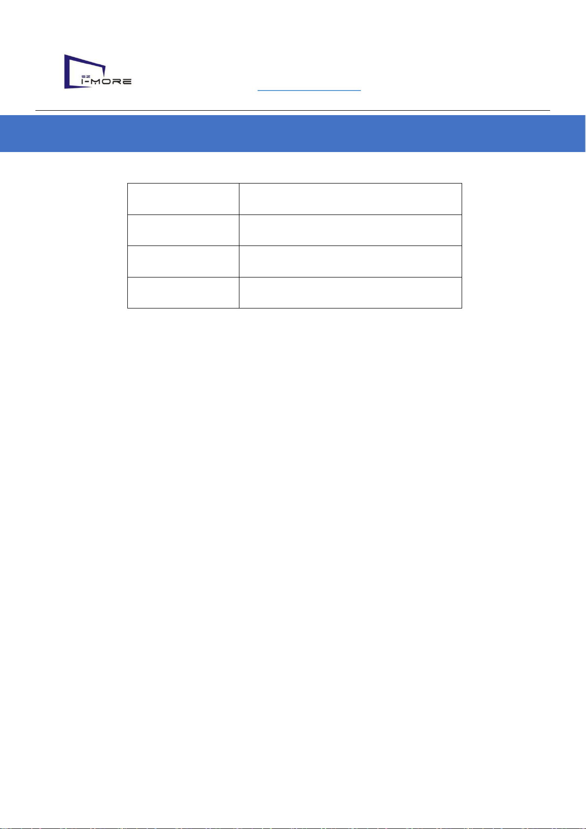
3.1. Accessories packing list
No
Name
Photos
Specification model
QT
Y
1
Shelf Led
Display
600*60mm/900*60mm/1200
*60mm
shelf display
4
2
Header
display
900*480mm/1200*360mm
header display
1
3
Power box
300L*160W*420Hmm
Weight 2KG
1
4
Sending
box
Nova TB3
1
5
Spare parts
1. LAN cable; 2. Power
cable;3. Adapters (if
needed)
1
6
Control
system
software
NovaLCT, Viplex
1

5|20
3.2. Safety instructions
★ The input voltage range of this product is 100-240VAC, 50 / 60Hz, please connect to the
correct power
★ This product uses 24VDC 2A input, please use with the power control box
★ Before connect or disconnect any cable, make sure that the power switch is turned off
★Before adding more output terminals, make sure that the power switch is turned off
★ Please use for indoor environment, do not put this product into high temperature, humid
and other environments
★ This product is electronic products, please stay away from fire, water and flammable and
explosive dangerous goods
★ This product has high-voltage components inside the control box, please do not open the
chassis or modify and repair it
★ If you find any smoke, smell and other unusual circumstances, please immediately turn off
the power switch, and contact the dealer

6|20
3.3 Specification
NO.
Item
Unit
Parameter/specification
Note
1
Shelf Led Display
mm
L600*H60*T26 mm/set
L900*H60*T26 mm/set
L1200*H60*T26 mm/set
2
Header display
mm
L900*H480*T65mm
L1200*H360*T65mm
3
Weight
Kg
0.65 Kg
main controller not
included
4
Pixel pitch
mm
1.875 mm
5
LED Configuration
-
1R 1G 1B
6
Shelf Signage Power
consumption Max
W/Pc
32/48/64 W/set
white balance
testing
7
Operating Voltage
V
DC 24 V
8
Maximum current
A
1.0 A
9
Brightness
Nit
≥600 Nit
10
Refresh rate
Hz
≥1920Hz
11
Frame frequency
Hz
120Hz
12
Gray scale
Bit
16Bit
13
Operating temperature
℃
-10-45℃
17
Working humidity
-
10-90%
18
IP defense
-
IP 30
19
Storage condition
-
-20--65℃ 10-90%

7|20
4. Hardware installation
4.1 Hardware installation appearance.
Header display
Power box
Shelf LED display
8|20
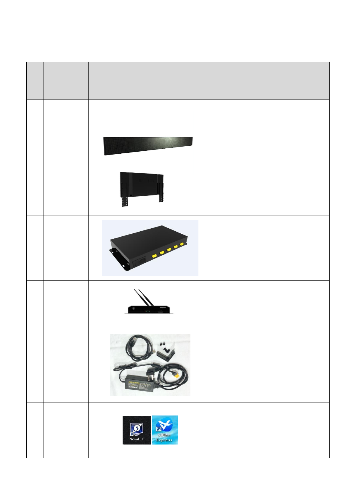
4.2 Shelf installation method.
4.2.1 Fix the mounting bracket on Shelf LED by screws offered.
4.2.2 Fix the shelf signage onto the shelf by screws.
4.2.3 Fix the power box.

9|20
4.3 Cables connection.
4.3.1. Power cable connection.
Option 1:
Option 2:
220V power box
220V power box
10 |20
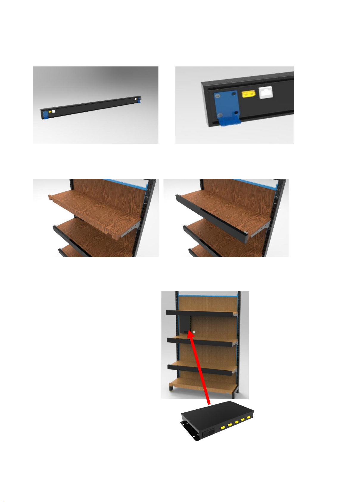
4.3.2 Signal cable connection.
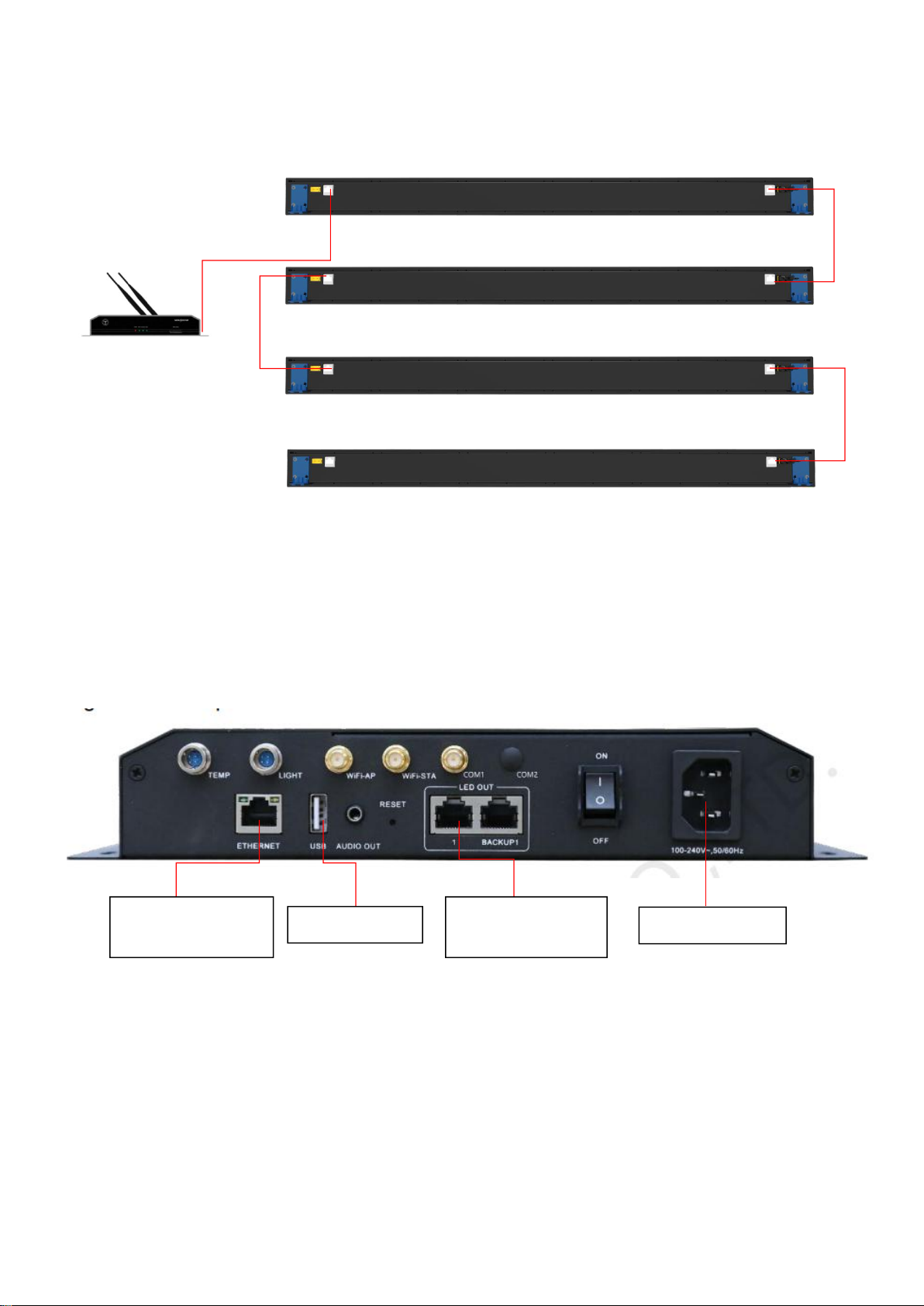
TB3 sending box
TB3 sending box connection cables
Lan cable connect to
internet
USB stick upload
Lan cable connect to
shelf signage
Power connector

11 |20
5. Software Instruction
5.1. Need to install two software(NovaLCT & Viplex) on a windows computer, the computer
needs be able to connect WIFI. Software download link:
https://drive.google.com/open?id=1C0_PBGYCeeB3kHI4Su-ihYaqe5iakrcr
5.2. Before You Begin
Acquire the SSID and password of Wi-Fi AP of the Taurus. SSID is default to be composed of AP
and the last 8 numbers of SN, and the password is default as “12345678”. Acquire the login
password of user “admin” of which the default password is “123456”.
Operating procedures:
Step 1 Connect the Wi-Fi AP of Taurus series products.
Step 2 Start the ViPlex Express.
Step 3 Click Refresh and the screen list will be displayed on the page.
denotes that Taurus is online and you can log into it.
: denotes that Taurus is offline and you cannot log into it.
: denotes that Taurus login is successful.
After the Taurus is found by ViPlex Express, the ViPlex express will try to log into to the Taurus with
the default account or the account used for last login.
Step 4 Taurus login is successful or not.
Yes. appears and no further operation is required.
No. appears and then perform Step 5.
Step 5 Click Connect on the right of the screen information.
Step 6 Enter the username and password, and click OK. Login password of user “admin” of
which the default password is “123456”.
12 |20
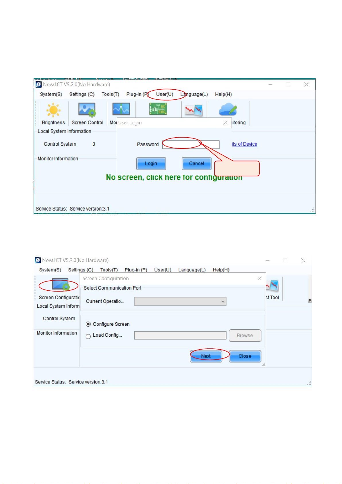
5.3. Nova LCT software configuration.
5.3.1 Open Software. Click User to login advanced Synchronous user login, input
default pass code “666”
5.3.2. Click ”Screen Configuration”, get into the mapping pages.
Enter 666
13 |20
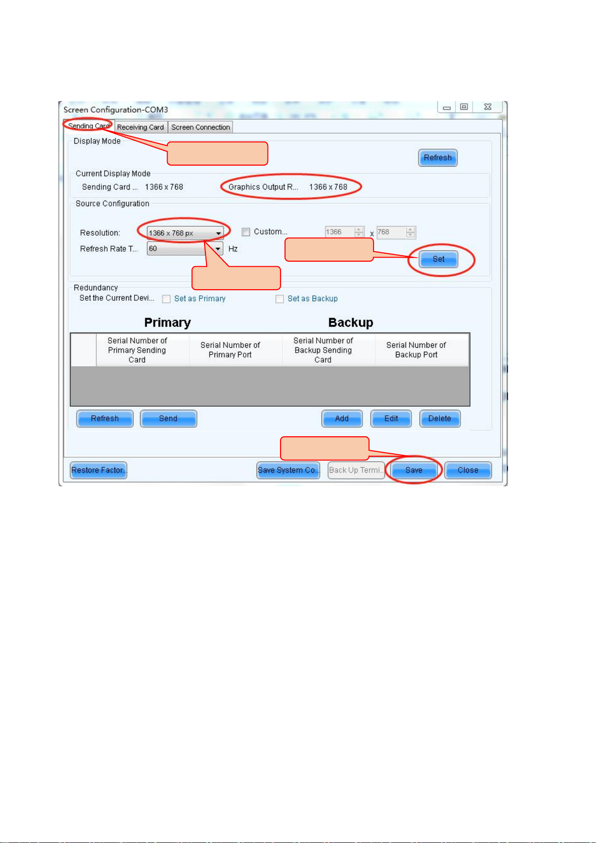
5.3.3. Click ”Screen Configuration”, get into the mapping pages. Make sure the Graphics
output resolution to be same as the sending card resolution.
Step.1
Step.2
Step.3
Step.4
14 |20
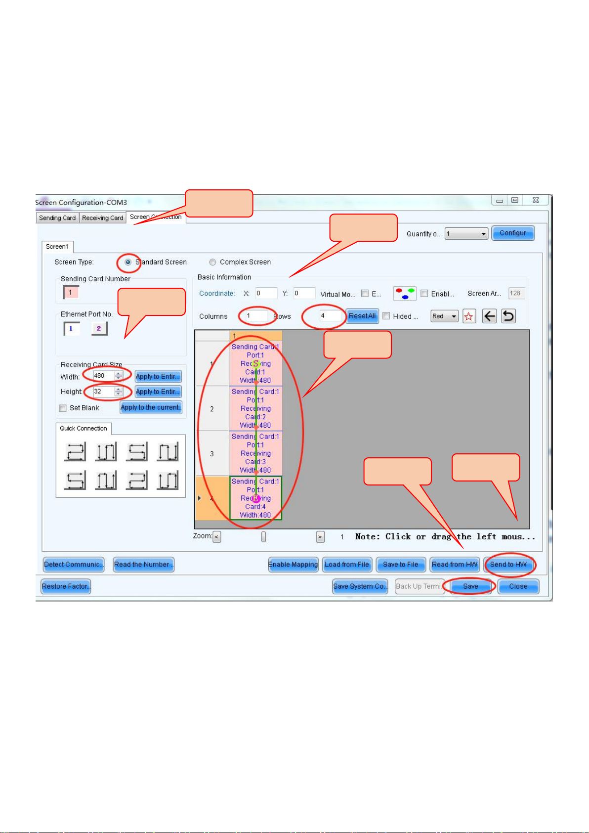
5.3.4. Click ” Screen Connection, get into the page. Make sure the Graphics output
resolution to be same as the sending card resolution. Pls note: Step .3. 900*60mm shelf display
resolution is 480*32, 600*60mm shelf display resolution is 320*32.
Step.1
Step.2
Step.3
Step.4
Step.5
Step.6

15 |20
6. Program playlist.
6.1 Running the viplex software, click “Solution” to input the resolution. There are 4 lines
with 900*60mm, so the resolution will be 480px in wide, 128px in high.
6.2 Upload the video or pictures.
Step.1
Step.3
Step.4
Step.1
Step.2
Step.2

16 |20
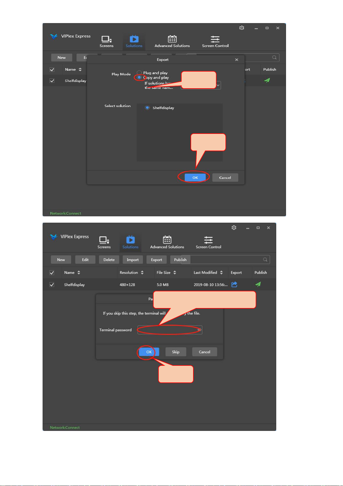
6.3 Export the playlist to USB stick. Plug USB stick into the computer, then export the
playlist to USB, plug into TB3, then Shelf led display will download the playlist to display.
Step.3
Step.1
Step.2
Step.3
17 |20
Step.4
Step.5
Step.6.passcode:123456
Step.7

18 |20
7. Common troubleshooting
7.1. Controller box power indicator not on.
7.1.1. Check whether the control box power cable is connected.
7.1.2. If the control box power cable is connected, but the power indicator still not on.
7.1.3. Change new power cable.
7.2. Control box power indicator on, but LED display not on.
7.2. 1. Confirm whether the control box is connected with LED display.
7.2.2. Change new DB15 output main cable, confirm whether it can light the screen.
7.2.3. Use USB serial cable connect computer and controller box, open software “LEDvision”
on computer, confirm whether control box configuration is correct.
7.2. 4. Use USB serial cable resend the program, upgrade a picture format program page if
necessary to check if it works or not.
7.3. LED screen works, but the display is abnormal.
7.3. 1. Use USB serial cable connect computer and controller box, open computer software,
confirm whether control box configuration is correct.
7.3.2. Use USB serial cable resend the program, upgrade a picture format program page if
necessary.
7.3.3. Change another LED screen, confirm whether LED display have hardware faults.
7.3.4. Change another controller box, confirm whether controller box have hardware faults.
7.4. When multiple LED screes splice, display normal but the whole image not connected.
7.4.1. Use USB serial cable connect computer and controller box, open software “LEDvision”
on computer, confirm whether control box configuration is correct.

19 |20
7.4.2. Use USB serial cable resend the program, upgrade a picture format program page if
necessary.
7.4.3. Check LED display connecting wiring again, to check if it is same wiring method like in
the software on computer.
8. Warranty
8.1. Free Warranty Commitment
8.1.1. All the hardware and software products to provide the original manufacturer of two
years free maintenance services, system technical support and upgrade services, including
one year free parts replacement (any one square meter appears four or more dead pixels
are required to be replaced) ,
8.1.2. The free warranty period is calculated from the date of signing of the "Goods
Acceptance Report" and is free of charge or replacement due to damage caused by the
quality of the equipment.
8.2. Technical documentation services
In the delivery of this product, our company will provide users with the appropriate technical
documentation, including manuals, technical specifications and other complete and accurate
engineering data.
8.3. The warranty service after the expiration
In the after-sales service process, we will store corresponding number of spare parts in
after-sales service network around cities based on the actual situation. If you need to replace the
equipment parts, we can immediately provide the same quality and same performance spare
parts to ensure the normal operation of the equipment.
8.3.1 The original equipment manufacturers sets up product spare parts warehouse to ensure
the timely maintenance of hardware equipment and replacement.

20 |20
8.3.2 After the warranty period, the company will regularly visit the owners to help the
owners to solve some specific problems in use, and to provide the latest relevant technical
information. Setting up the corresponding customer files, recording each technical problems and
specific solutions and processes. Commitment to the owners to provide long-term technical
support and advisory services.
8.3.3 During the warranty years, offer free whole life technical consulting service, and offer
series installation spare parts and maintenance with a lower price than local market.
8.3.4 We commit to the buyer: within 5 years from the date of "goods acceptance report"
signed, we provide equipment-adequate machine and maintenance spare parts. After 5 years, if
the equipment manufacturer stop supplying machine or spare parts, we will inform the buyer to
do appropriate preparation ahead of 6 months.
Table of contents


