Innes SLATE106 User manual

SLATE106
Installation guide

1
INNES
ZAC Atalante champeaux
5A rue Pierre Joseph Colin
35000 RENNES
France
Technical support
Email: support@innes.fr
Tel: +33 (0)2 23 20 01 62
Fax: +33 (0)2 23 20 22 59
SLATE106-installation-guide-006A_en
Product information
The conception and specifications of the product may
change without prior notice, and this applies to
hardware, embedded software and this guide.
Consumable items accessories may slightly differ than
herein described as INNES is depending on the
evolutions of its suppliers.
This document contains confidential information; it can’t
be disclosed to any third parties without prior written
authorization of INNES.
Safety instructions
Please read carefully the following instructions before
switching the product on:
- WARNING! Correct fitting and installation is of
the utmost importance. Incorrect fitting
and/or installation may result in personal
injury or loss. INNES disclaims all liability, of
whatever kind, if the product is assembled,
fitted and/or installed in an incorrect manner.
- Do not use the product near a water supply.
- Do not pour anything on the product, like
flammable liquids or material.
- Do not expose the product to direct sun, near
a heating source or a dust nor vibrations.
- Do not obstruct holes, to be sure that air flows
freely around the product.
- Switch off the product during a storm.
- Do not open the product in any circumstances.
- Keep this guide, preciously.
Safety instructions, guarantee terms
INNES products are eligible for a warranty to cover
genuine manufacturing defect for 3 years.
Product failure occurring as the result of factors that do
not constitute genuine manufacturing defect are not
covered under the terms of the warranty and any repairs
of this nature would be chargeable.
For example:
Inappropriate maintenance action, a non-authorized
modification, a not specified environment utilization (see
‘Safety instructions’), or if the product has been
damaged after an impact, a fall, a bad manipulation or a
storm consequence, an insufficient protection against
heat, moisture or frost.
This warranty is not transferrable. In addition, any
repairs carried out by non-authorized personnel will
invalidate the warranty.
This symbol means that your end of life equipment must
not be disposed of with household waste but must be
deposited at a collection point for waste electrical and
electronic equipment. This will benefit the environment.
In this context, a system for collecting and recycling has
been implemented by the European Union

2
1 Getting started _____________________________________________________________________ 3
Recommendations and warnings __________________________________________________________ 3
Packing list ____________________________________________________________________________ 3
Installation ____________________________________________________________________________ 4
1.3.1 Batteries ______________________________________________________________________________________ 4
1.3.1.1 Specifications _____________________________________________________________________________ 4
1.3.1.2 Installation _______________________________________________________________________________ 4
1.3.1.3 Replacement ______________________________________________________________________________ 6
1.3.2 Wall mount ___________________________________________________________________________________ 7
Block diagram _________________________________________________________________________ 8
Peripherals positioning __________________________________________________________________ 9
2 Identification with serial number ______________________________________________________ 10
3 Different device phases at start-up ____________________________________________________ 11
4 LED behavior ______________________________________________________________________ 11
5 Hardware reset ____________________________________________________________________ 12
6 Recovery mode ____________________________________________________________________ 13
7 Start-up __________________________________________________________________________ 15
8 Pictureframe application ____________________________________________________________ 16
Spe desktop __________________________________________________________________________ 16
8.1.1 Operating ____________________________________________________________________________________ 16
8.1.2 Test card ____________________________________________________________________________________ 19
8.1.3 Switch to Hub mode ___________________________________________________________________________ 19
8.1.4 Release ______________________________________________________________________________________ 19
Central hub __________________________________________________________________________ 20
8.2.1 Operating ____________________________________________________________________________________ 20
8.2.2 Configuration of SMH300 and SLATE106 ___________________________________________________________ 20
8.2.3 Configuration of SMH300 App ___________________________________________________________________ 22
8.2.4 Working range ________________________________________________________________________________ 22
8.2.4.1 PictureFrame version 1.10.12 (and below) _____________________________________________________ 22
8.2.4.2 PictureFrame version 1.10.13 (and above) _____________________________________________________ 22
8.2.5 Test card ____________________________________________________________________________________ 24
8.2.6 Switch to spe desktop __________________________________________________________________________ 24
8.2.7 Software release ______________________________________________________________________________ 24
8.2.8 SLATE106 device or SMH300 device replacement ____________________________________________________ 25
8.2.9 State diagram_________________________________________________________________________________ 26
9 RFID/NFC _________________________________________________________________________ 27
10 Technical specifications ____________________________________________________________ 28

3
1 Getting started
This installation guide explains how to install SLATE106 and how to use it.
Recommendations and warnings
Batteries:
The SLATE106 is designed to work with CR2430 batteries (4 units). Innes has chosen a battery model
having the best performances for SLATE106 using. Please refer to the batteries replacement chapter to
know how to replace them.
Lifetime is estimated to 3 years when configured with a usage of four display content updates per day
with Bluetooth Low Energy synchronization and connected to a SMH300 device. Lifetime can be
increased or decreased when the usage is modified.
In case of batteries replacement, the four batteries need to be changed at the same time.
The batteries must be changed by a qualified person, who is knowing perfectly the batteries
replacement procedure. Batteries must be recycled according to your country’s regulations.
Warranty does not cover the batteries.
Packing list
Articles Model – function
Device SLATE106
Batteries 4 CR2430 batteries with plastic holder
Wall mount Wall mount support
Screws 2 M2.5x25 screws
Adhesive 3M double-sided tape (W x H x D): 65 x 19 x 0.5 mm

4
CR2430
+
Installation
1.3.1 Batteries
1.3.1.1 Specifications
The SLATE106 devices are delivered with 4 CR2430 Lithium coin batteries. The main batteries features are
described below. Use the same reference to expect the best lifetime. However an equivalent reference may be used.
Type CR2430
Nominal Voltage 3V
Typical Capacity 290mAh
Chemical System Lithium Manganese Dioxide
Reference 2430/CR2430 VP-1 ENERGIZER LITHIUM [Energizer]
1.3.1.2 Installation
1. Refer to Pictureframe application chapter, to determine if you need to install batteries into your SLATE106
(few use cases can run without battery).
2. Place the SLATE106, with the back face in front of you.
3. Take on the box a battery by keeping its plastic holder:
(in case the battery is not delivered with its holder, call Innes support)
CR2430 battery
Battery holder

5
4. Glide the battery with its holder into its place using your finger or a screwdriver to push the plastic of holder
part until you feel a clip, meaning that the battery is properly installed:
CR2430
+
CR2430
+
CR2430
+
CR2430
+
CR2430
+
1
2 3
4
Back of the SLATE106
5. Repeat step 2 & 3 for each battery by following the specific orientation for each place like shown above.
Once installed, the batteries are all hidden.

6
1.3.1.3 Replacement
1. Remove each battery with holder, using a little slotted screwdriver. Grab and then pull the edge of the
plastic holder, remove the old battery from the holder.
CR2430
+
CR2430
+
Grab the edge of holder Pull the holder
2. Insert the new battery with the positive side facing up. Glide the battery with holder into place using your
finger or screwdriver pushing into the plastic of holder part: you must feel a clip when the battery is
installed.
CR2430
+
CR2430
+
Insert new battery
Glide battery and holder
3. Repeat operation 1 and 2 for each battery.

7
Holes
for fixing the
SLATE106
are
facing downward
Counterbores are facing to you (to
integrate the screw head)
1.3.2 Wall mount
The SLATE106 device must be used indoor and can be installed using the provided wall mount. This support can be
fixed by:
using screws (not delivered with product and dependent on your wall type) or
using the provided double-sided tape (more particularly for mounting on smooth surface like glass).
1. Fix the wall mount using the drill pattern document (ref ‘DS-SLATE106DRP-A.pdf’, available on the website
http://www.innes.pro/fr/support/index.php?SLATE106/PictureFrame for a proper placement of the support.
Be careful that the wall mount has a right orientation:
2. Once the wall support is fixed with screw or adhesive, place SLATE106 face to the support and insert the
SLATE106 into it. Hold the SLATE106 into place and put the 2 M2.5x25 screws provided using a little slotted
screwdriver.
M2.5x25 screw

8
Block diagram
(Dimension in mm)
151,2
114
8
Micro
USB
type B
connector
Holes for wall mount fixing

9
Peripherals positioning
For interactivity, the SLATE106 device has
3 touch sensing keys
3 red LEDs
1 RFID sensor
Please find below location of each peripheral:
Right key
Left key
Middle key
Right LED
Left LED
Middle LED
RFID sensor

10
Detailled positions (mm):
2 Identification with serial number
The SLATE106 devices works with a proprietary Innes software.
A stamp permits to show the device information like its PSN and its MAC address.
Note: In case technical support is requested, the serial number (starting with ‘PSN’) could be required to go ahead on technical analysis:

11
3 Different device phases at start-up
4 LED behavior
The LEDs behavior is depending on these SLATE106 application steps:
LED
s
b
ehavior
Information
Step 1
Start-up
Off
Nominal: no important user information to
return
The
3
LED
s
are
blinking 1 time
Start
-
up
The l
eft
LED
is
blinking 5 times
Phase 1 to enter in recovery mod
e
(*1)
The r
ight
LED
is
blinking 5 times
Phase 2 to enter in recovery mode
(*1)
The l
eft
LED
is
blinking
Release in p
r
ogress
. The duration of the
release process depends on the size of the
release, and is around 1 minute.
The
3
LED
s
are
blinking 1 ti
me
slowly
There is no
more
valid software
on Slate:
going into sleep mode, and then in recovery
mode when an USB cable will be connected
The
3
LED
s
are
blinking
continuously and slowly
Error
(*2
)
Step 2
Recovery
Mode
The l
eft
LED
,
and
the
right
LED
are turned on
Recovery mode activated
The m
iddle
LED
is
blinking
File copying in USB on Slate
The
3
LED
s
are
blinking
continuously and slowly
Error
(*2
)
Step
3
Nominal
mode
Off
Nominal: no important user information to
return
The l
eft
LED
and
the
rig
ht
LED
are blinking 1 time
Enter in nominal mode
3
LED
s
are
blinking continuously
and slowly
Error
(*2
)
(*1) Phases to enter in recovery mode exist only if a USB cable is connected.
(*2) Error condition has 2 behaviors: 1) If an USB cable is connected, the 3 LEDs are blinking slowly – when the cable is removed, the SLATE106
device is rebooting. 2) If no USB cable is connected, the SLATE106 device is rebooting. If the problem persists, contact INNES technical support.
Step 1
Start-up
Phase during first starting or
after hardware reset
Step 2
Recovery mode
This phase is performed
only if recovery mode
procedure is completed
Step 3
Nominal mode
Common Slate106
functioning
T = 0
Time
T ~6 sec to access
recovery mode
procedure
T ~9 sec if skip recovery mode procedure
T ~3 sec if no recovery mode
12
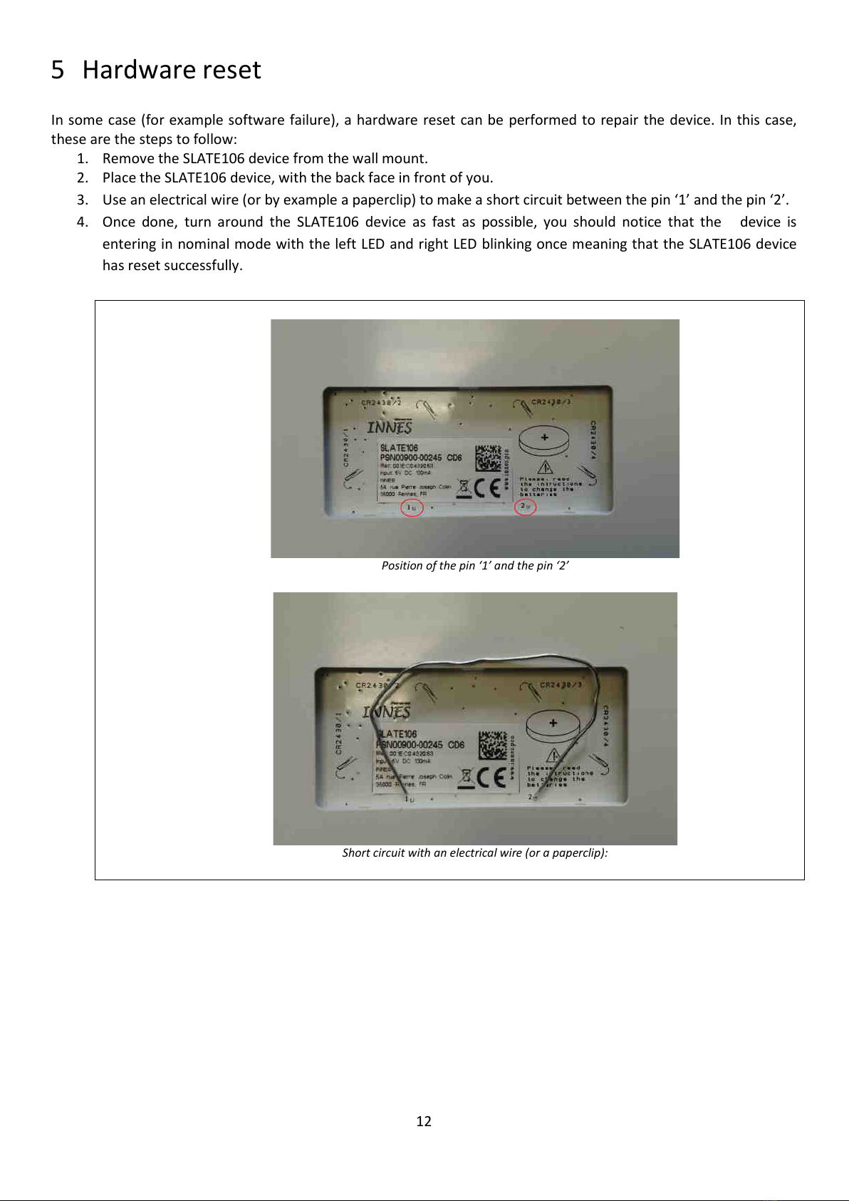
5 Hardware reset
In some case (for example software failure), a hardware reset can be performed to repair the device. In this case,
these are the steps to follow:
1. Remove the SLATE106 device from the wall mount.
2. Place the SLATE106 device, with the back face in front of you.
3. Use an electrical wire (or by example a paperclip) to make a short circuit between the pin ‘1’ and the pin ‘2’.
4. Once done, turn around the SLATE106 device as fast as possible, you should notice that the device is
entering in nominal mode with the left LED and right LED blinking once meaning that the SLATE106 device
has reset successfully.
Position of the pin ‘1’ and the pin ‘2’
Short circuit with an electrical wire (or a paperclip):

13
6 Recovery mode
The recovery mode allows the (re)installation of a new SLATE106 software. Be aware that in recovery mode, the
whole file system will be erased, and will have to be formatted again by the user.
To perform this operation, you need:
To remove the SLATE106 device from its wall mount
A Micro USB type B to USB cable (like standard charging smartphone cable)
A Paperclip
A computer to link to the SLATE106
1. Place the SLATE106, with the back face in front of you.
2. Connect the USB cable between your computer and the SLATE106 device (no recovery mode without USB
connected).
3. Use an electrical wire (or a paperclip) and make a short circuit between the pin 1 and the pin 2. That will
perform a hardware reset.
4. Turn around the SLATE106, the 3 LEDs will blink shortly (you may not have time to see this LED blinking).
5. Few seconds after, the left LED is blinking 5 times
Press
now
the left key
after
this
LED
blinking
(you have 2 seconds to perform this operation, otherwise software is launched normally and you should return to step 3 to reach recovery
mode).
6. After the left key is pressed, right LED is blinking 5 times
Press
now
the right key
after
this
LED
blinking
(you have 2 seconds to perform this operation, otherwise software is launch and you should return to step 3 to reach recovery mode).
7. The left LED and the right LEDs are turned on, you are now in recovery mode. The file system is
automatically erased.
8. The mass storage should be detected on your computer, and it should be asked for starting a format
operation. Select FAT file system for SLATE106 (only FAT partition is supported) and press START.
After few seconds, the format is completed; Your volume should appear like a mass storage.
9. copy a new firmware on the SLATE106 device
10. Eject the mass storage.

14
This is the state diagram of the recovery mode activation with a SLATE106 device hardware reset:

15
7 Start-up
The start-up process (bootloader) does two main operations:
Manage recovery mode
Update the application in case a firmware file already exists.
This is the simplified state diagram of the start-up process:

16
8 Pictureframe application
The SLATE106 device with embedded Pictureframe application can be used in 2 ways:
With a central hub, like SMH300
With spe desktop software or (spe mobile software).
The factory default mode permits to use both the spe desktop software and a central hub SMH300:
Once Pictureframe has been configured to be used with a central hub SMH300, the spe desktop software
cannot be used anymore (without any specific operation).
Once spe desktop has been used, it is still possible to configure Pictureframe to be used with a central hub
To go back to factory default, you must erase the Pictureframe configuration file, by connecting the SLATE106 to a
computer with a micro USB type B to USB cable. Once the mass storage is mounted, delete the configuration file
‘APPLI.CFG’ (or ‘PF.CFG’ for version < V1.10.12), and eject properly the USB device. Once the USB mass storage is
mounted again, you can disconnect the cable.
Spe desktop
8.1.1 Operating
Spe desktop permits to use a SLATE106 device with a MS-Windows PC connected with a USB cable.
Connected to the PC, the SLATE106 device can work without batteries.
Spe desktop must be copied in the SLATE106 device (‘spe.exe’). Visit the Innes Web site to get the latest Spe
Desktop version: http://www.innes.pro/fr/support/index.php?Slate106/SPE_Desktop.
To copy Spe desktop on your SLATE106 device, you need:
a SLATE106 device
a Micro USB type B to USB cable (like standard charging smartphone cable)
A MS-Windows PC (linked to the SLATE106 device).
1. Connect USB cable between your computer and the SLATE106 device.
2. Wait for the SLATE106 device mounting as a mass storage in MS-Windows, and execute ‘spe.exe’ directly
from SLATE106 disk.
3. Edit your text with spe desktop software like any text editor: enter your text, change size, select grey level,
change font.
for specific font, copy the text with the specific from another editor and paste it in spe desktop editor

17
4. When finished, use ‘Save to Slate’ under the ‘File’ menu. Your picture is saved automatically with the file
name ‘spe.ppk’ on your SLATE106. Your content should be displayed on SLATE106.
5. Remove USB cable
The SLATE106 will be remounted automatically as a mass storage until the USB cable is disconnected.
Grey level selection

18
This is the simplified state diagram of Pictureframe application when used with spe desktop:

19
8.1.2 Test card
The test card replaces the previous image content, and should give information(1) about the SLATE106 device. The
test card is activated by default with Pictureframe.
(1) until there, the test card is displaying a blank screen and is displaying no device information. It should be supported in a next version
You have 2 ways to inactivate the test card in spe desktop mode:
- Method n°1 (preferred one): Remove the configuration file if it exists, and generate an image with spe
desktop (‘spe.ppk’). Once these 2 conditions are filled, pictureframe is generating automatically a new
configuration file with test card inactivated.
- Method n°2: If a configuration file exists, edit it, and change the key which is corresponding to test card.
You have 2 ways to activate the testcard in spe desktop mode:
- Method n°1 (preferred one): Remove the configuration file if it exists, and remove or rename the image
‘spe.ppk’. It activates the test card as default factory state.
- Method n°2: If a configuration file exists, edit it, and change the key which is corresponding to test card.
8.1.3 Switch to Hub mode
To switch from spe desktop mode to Hub mode, you must declare and pair your SLATE106 device in the SMH300
hub (WebUI).
8.1.4 Release
To update your pictureframe software version:
1) connect a computer to your SLATE106 device with an USB cable.
2) Once mass storage is mounted, copy the release file ‘*.rpk’.
3) Eject properly your USB device.
Then the SLATE106 device
reboots,
upgrades its software (unless it is already to the new version) and
removes the release file.
Once the mass storage is mounted again, your SLATE106 device is up-to-date.
Table of contents
Other Innes Digital Signage manuals


