IN-ECO AG110018 User manual

说明书材质要求:105g铜版纸
说明书成品尺寸: 120x170mm
第一:专色用6级防晒油墨+CMYK油墨要求:
1.
PANTONE137C专色油墨(
专色用6级防晒油墨):
如果自己配色,油墨配比为:泗联中黄
(
防晒)2000g
泗联金红
(
防晒)
225g
2.
C色油墨:泗联天蓝墨
3.
M色油墨:泗联金红墨
4.Y色油墨:pantone123C专色油墨
5.K色油墨:泗联黑墨
第二:特别注意:
1.印刷时看样请参考我司提供的实物样品颜色。不得偏色
2.137C的专色不得参考C=0,M=35,Y=90,K=0对应的四
色色谱颜色来看样印刷
折叠方式:骑马钉/胶装/风琴折
如有其他方式再讨论
备注:
特别注意:此页内容不印刷

Angle Grinder
EN Angle Grinder
AG110018 UAG110018 AG110018-4
AG110018-6 AG110018-8 AG110018S AG110018E
INGCO Global
INGCO Global

2|English
The symbols in instruction manual and the label on the tool
Double insulated for additional protection.
Read the instruction manual before using.
CE conformity.
Wear safety glasses, hearing protection and dust mask.
Wasteelectricalproductsshouldnotbedisposedofwith householdwaste.
Please recycle where facilities exist. Check with your Local Authority or
retailer for recyclingadvice.
Safety alert.
Please only use the accessories supported by the manufacturer.

3|English
WARNING Read all safety warnings and all instructions. Failure to
follow the warnings and instructions may result in electric shock, fire and/or
serious injury.
Save all warnings and instructions for future reference.
The term "power tool" in the warnings refers to your mains-operated (corded)
power tool or battery-operated (cordless) power tool.
1) Work area safety
a) Keep work area clean and well lit. Cluttered and dark areas invite
accidents.
b) Do not operate power tools in explosive atmospheres, such as
in the presence of flammable liquids, gases or dust. Powertools
create sparks which may ignite the dust orfumes.
c) Keep children and bystanders away while operating a power
tool. Distractions can cause you to losecontrol.
2) Electrical safety
a) Power tool plugs must match the outlet. Never modify the plug
in any way. Do not use any adapter plugs with earthed
(grounded) power tools. Unmodified plugs and matching outlets will
reduce risk of electric shock.
b) Avoid body contact with earthed or grounded surfaces such as
pipes, radiators, ranges and refrigerators. There is an increased
risk of electric shock if your body is earthed orgrounded.
c) Do not expose power tools to rain or wet conditions. Water
entering a power tool will increase the risk of electric shock.
d) Do not abuse the cord. Never use the cord for carrying, pulling
or unplugging the power tool. Keep cord away from heat, oil,
sharp edges or moving parts. Damaged or entangled cords
increase the risk of electric shock.
e) When operating a power tool outdoors, use an extension cord
suitable for outdoor use. Use of a cord suitable for outdoor use
reduces the risk of electric shock.
f) If operating a power tools in a damp location is unavoidable, use
GENERAL POWER TOOL SAFETY WARNINGS

4|English
a residual current device (RCD) protected supply. Use of an RCD
reduces the risk of electric shock.
3) Personal safety
a) Stay alert, watch what you are doing and use common sense
when operating a power tool. Do not use a power tool while you
are tired or under the influence of drugs, alcohol or medication.
A moment of inattention while operating power tools may result in
serious personal injury.
b) Use personal protective equipment. Always wear eyeprotection.
Protective equipment such as dust mask, non-skid safety shoes,
hard hat, or hearing protection used for appropriate conditions will
reduce personal injuries.
c) Prevent unintentional starting. Ensure the switch is in the off-
position before connecting to power source and/or battery pack,
picking up or carrying the tool. Carrying power tools with your
finger on the switch or energizing power tools that have the switch on
invites accidents.
d) Remove any adjusting key or wrench before turning thepower
tool on. A wrench or a key left attached to a rotating part of the
power tool may result in personal injury.
e) Do not overreach. Keep proper footing and balance at all times.
This enables better control of the power tool in unexpected
situations.
f) Dress properly. Do not wear loose clothing or jewellery. Keep
your hair, clothing and gloves away from moving parts. Loose
clothes, jewellery or long hair can be caught in moving parts.
g) If devices are provided for the connection of dust extraction and
collection facilities, ensure these are connected and properly
used. Use of dust collection can reduce dust-relatedhazards.
4) Power tool use and care
a) Do not force the power tool. Use the correct power tool for your
application. The correct power tool will do the job better and safer at
the rate for which it was designed.
b) Do not use the power tool if the switch does not turn it on and off.
Any power tool that cannot be controlled with the switch is dangerous

5|English
and must be repaired.
c) Disconnect the plug from the power source and/or the battery
pack from the power tool before making any adjustments,
changing accessories, or storing power tools. Such preventive
safety measures reduce the risk of starting the power toolaccidentally.
d) Store idle power tools out of the reach of children and do not allow
persons unfamiliar with the power tool or these instructions to
operate the power tool. Power tools are dangerous in the hands of
untrained users.
e) Maintain power tools. Check for misalignment or binding of
moving parts, breakage of parts and any other condition that may
affect the power tools operation. If damaged, have the power tool
repaired before use. Many accidents are caused by poorly maintained
power tools.
f) Keep cutting tools sharp and clean. Properly maintained cutting tools
with sharp cutting edges are less likely to bind and are easier to control.
g) Use the power tool, accessories and tool bits etc. in accordance
with these instructions, taking into account the working
conditions and the work to be performed. Use of the power tool for
operations different from those intended could result in a hazardous
situation.
5) Service
a) Have your power tool serviced by a qualified repair person using
only identical. This will ensure that the safety of the power tool is
maintained.6

6|English
Additional SafetyWarnings
Safety iinstructiions for allll operatiions
Safety Warnings Common for Grinding, Sanding, Wire Brushing, Polishing or Abrasive Cutting-
Off Operations:
a)
This power tool is intended to function as a grinder, sander, wire brush, polisher or cut-off
tool. Read all safety warnings, instructions, illustrations and specifications provided with this
power tool. Failuretofollow all instructions listed below may result inelectric shock, fireand/or serious
injury.
b)
Operations such as grinding, sanding, wire brushing, polishing or cutting-off are not
recommended to be performed with this power tool. Operations for which the power tool was not
designed may create a hazard and cause personalinjury.
c)
Do not use accessories which are not specifically designed and recommended by the tool
manufacturer. Just because the accessory can be attached to your power tool, it does notassuresafe
operation.
d)
The rated speed of the accessory must be at least equal to the maximum speed marked on the
power tool. Accessories running faster than their rated speed can break and fly apart.
e)
The outside diameter and the thickness of your accessory must be within the capacity rating of
your power tool. Incorrectly sized accessories cannot be adequately guarded or controlled.
f)
Threaded mounting of accessories must match the grinder spindle thread. For accessories mounted by
flanges, the arbour hole of the accessory must fit the locating diameter of the flange.
Accessories that do not
match the mounting hardware of the power tool will run out of balance, vibrate excessively and may cause loss of
control.
g)
Do not use a damaged accessory. Before each use inspect the accessory such as abrasive
wheels for chips and cracks, backing pad for cracks, tear or excess wear, wire brush for loose or
cracked wires. If power tool or accessory is dropped, inspect for damage or install an
undamaged accessory. After inspecting and installing an accessory, position yourself and
bystanders away from the plane of the rotating accessory and run the power tool at maximum no-
load speed for one minute. Damaged accessories will normally break apart during this test time.
h)
Wear personal protective equipment. Depending on application, use face shield, safety
goggles or safety glasses. As appropriate, wear dust mask, hearing protectors, gloves and
workshop apron capable of stopping small abrasive or workpiece fragments. The eye protection
mustbecapable of stopping flying debris generated byvarious operations. Thedust mask orrespirator
mustbe capableoffiltrating particles generatedbyyour operation.Prolonged exposure to high intensity
noise may cause hearing loss.
i)
Keep bystanders a safe distance away from work area. Anyone entering the work area must
wear personal protective equipment. Fragmentsof workpiece orofa broken accessory may fly away
and cause injury beyond immediate area ofoperation.
j)
Hold the power tool by insulated gripping surfaces only, when performing an operation where
the cutting accessory may contact hidden wiring or its own cord. Cutting accessory contacting a
"live" wire may make exposed metal parts of the power tool "live" and could give the operator an electric
shock.
k)
Position the cord clear of the spinning accessory. If you lose control, the cord may becutor
snagged and your hand or arm may be pulled into the spinning accessory.
l)
Never lay the power tool down until the accessory has come to a complete stop. The spinning
accessory may grab the surface and pull the power tool out of your control.
m)
Do not run the power tool while carrying it at your side. Accidental contact with the spinning
accessory could snag your clothing, pulling the accessory into your body.
n)
Regularly clean the power tool’s air vents. The motor’s fan will draw the dust inside the housing

7|English
Further safety instructions for all operations
Additional safety instructions for grinding and cutting-off operations
and excessive accumulation of powdered metal may cause electrical hazards.
o)
Do not operate the power tool near flammable materials. Sparks could ignite these materials.
p)
Do not use accessories that require liquid coolants. Using water orother liquid coolants may
result in electrocution or shock.
Kickback and Related Warnings
Kickback is a sudden reaction to a pinched or snagged rotating wheel, backing pad, brush or any other
accessory. Pinching or snagging causes rapid stalling of the rotating accessory which in turn causes the
uncontrolled power tool to be forced in the direction opposite of the accessory’s rotation at the point of
the binding.
For example, if an abrasive wheel is snagged or pinched by the workpiece, the edge of the wheel that is
entering into the pinch point can dig into the surface of the material causing the wheel to climb out or kick
out. The wheel may either jump toward or away from the operator, depending on direction of the wheel’s
movement at the point of pinching. Abrasive wheels may also break under these conditions.
Kickback is the result of power tool misuse and/or incorrect operating procedures or conditions and can
be avoided by taking proper precautions as given below.
a)
Maintain a firm grip on the power tool and position your body and arm to allow you to resist
kickback forces. Always use auxiliaryhandle, ifprovided, for maximum control over kickback or
torque reaction duringstart-up. The operator can control torque reactions orkickback forces,ifproper
precautions are taken.
b)
Never place your hand near the rotating accessory. Accessory may kickback over your hand.
c)
Do not position your body in the area where power tool will move if kickback occurs. Kickback
will propel the tool in direction opposite to the wheel’s movement at the point of snagging.
d)
Use special care when working corners, sharp edges etc. Avoid bouncing and snagging the
accessory. Corners, sharp edges or bouncing have a tendency to snag the rotating accessory and
cause loss of control or kickback.
e)
Do not attach a saw chain woodcarving blade or toothed saw blade. Such blades create frequent
kickback and loss of control.
Safety Warnings Specific for Grinding and Abrasive Cutting-Off Operations:
a)
Use only wheel types that are recommended for your power tool and the specific guard
designed for the selected wheel. Wheels for which the power tool was not designed cannot be
adequately guarded and are unsafe.
b)
The grinding surface of centre depressed wheels must be mounted below the plane of the
guard lip. An improperly mounted wheel that projects through the plane of the guard lip cannot be
adequately protected.
c)
The guard must be securely attached to the power tool and positioned for maximum safety, so
the least amount of wheel is exposed towards the operator. The guard helps to protect the operator
from broken wheel fragments, accidental contact with wheel and sparks that could ignite clothing.
d)
Wheels must be used only for recommended applications. For example: do not grind with the
side of cut-off wheel. Abrasive cut-off wheels are intended for peripheral grinding, side forces applied
to these wheels may cause them toshatter.

8|English
Additional safety instructions for cutting-off operations
Additional safety instructions for sanding operations
Additional safety instructions for polishing operations
Additional safety instructions for wire brushing operations
e)
Always use undamaged wheel flanges that are of correct size and shape for your selected
wheel. Proper wheel flanges support the wheel thus reducing the possibility of wheel breakage. Flanges
for cut-off wheels may be different from grinding wheelflanges.
f)
Do not use worn down wheels from larger power tools. Wheel intended for larger power tool is not
suitable for the higher speed of a smaller tool and mayburst.
Additional Safety Warnings Specific for Abrasive Cutting-Off Operations:
a)
Do not “jam” the cut-off wheel or apply excessive pressure. Do not attempt to make an
excessive depth ofcut. Overstressing the wheel increases the loadingand susceptibility to twistingor
binding of the wheel in the cut and the possibility of kickback or wheel breakage.
b)
Do not position your body in line with and behind the rotating wheel. When the wheel, at the
point of operation, is moving away from your body, the possible kickback may propel the spinning wheel
and the power tool directly at you.
c)
When wheel is binding or when interrupting a cut for any reason, switch off the power tool and
hold the power tool motionless until the wheel comes to a complete stop. Never attempt to
remove the cut-off wheel from the cut while thewheel is in motion otherwise kickback may occur.
Investigate and take corrective action to eliminate the cause of wheel binding.
d ) Do not restart the cutting operation in the workpiece. Let the wheel reach full speed and
carefully re-enter the cut. The wheel may bind, walk up or kickback if the power tool is restarted in the
workpiece.
e)
Support panels or any oversized workpiece to minimize the risk of wheel pinching and
kickback. Large workpieces tend to sag under their own weight. Supports must beplaced under the
workpiece near the line of cut and near the edge of the workpiece on both sides of the wheel.
f)
Use extra caution when making a “pocket cut” into existing walls or other blind areas. The
protruding wheel may cut gasor water pipes, electrical wiring or objects that can cause kickback.
Safety Warnings Specific for Sanding Operations:
a) Do not use excessively oversized sanding disc paper. Follow manufacturers
recommendations, when selecting sanding paper. Larger sanding paper extending beyond the
sanding pad presents a laceration hazard and may cause snagging, tearing of the disc or kickback.
Safety Warnings Specific for Polishing Operations:
a) Do not allow any loose portion of the polishing bonnet or its attachment strings to spin freely.
Tuck away or trim any loose attachment strings. Loose and spinning attachment strings can entangle
your fingers or snag on the workpiece.
Safety Warnings Specific for Wire Brushing Operations:
a)
Be aware that wire bristles are thrown by the brush even during ordinary operation. Do not
overstress the wires byapplying excessive load to the brush. The wire bristles can easily penetrate
light clothing and/or skin.
b)
If the use of a guard is recommended for wire brushing, do not allow any interference of the
wire wheel or brush with the guard. Wire wheel or brush may expand in diameter due to work load
and centrifugal forces.

9|English
Residual risks
Even when the po wer tool is used as prescribed it is not possible to
eliminate all residual risk factors. The follo wing hazards may arise in
connection with the power tool’s construction and design:
a) Health defects resulting from vibration emission if the power tool is being
used over longer period of time or not adequately managed and properl y
maintained.
b) Injuries and damage to property to due to broken accessories that are
suddenly dashed.
Warning! This power tool produces an electromagnetic field during
operation. This field may under some circumstances interfere wi th active or
passive medical implants. To reduce t he risk of serious or fatal injury, we
recommend persons with medical impl ants to consult their phy sician and the
medical implant manufacturer before operating this power tool.
10|English
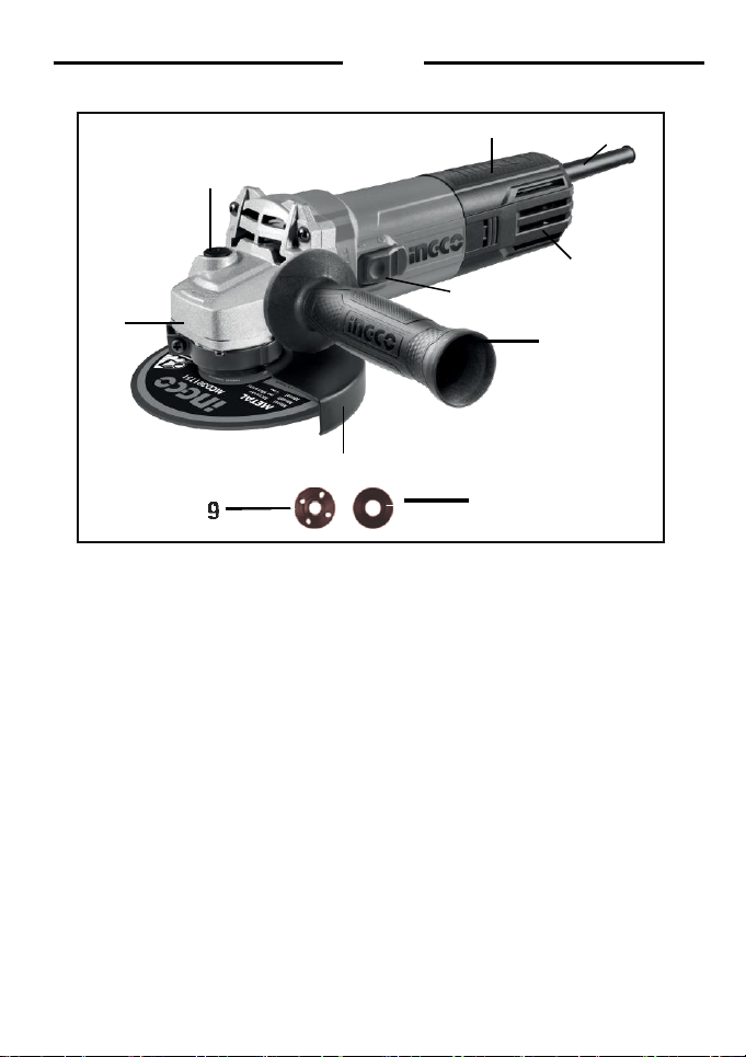
1. Spindle Locking Button
2. On / Off Switch Button
3. Handle
4. Power Cable Sleeve
5. Cooling Vents
6. Auxiliary Handle
7. Disc Guard
8. Direction Of Rotation Indicator
9. Outer Flange
10. Inner Flange
10
9
7
6
8
2
5
1
4
3

11|English
TECHNICAL DATA
Model No.
AG110018 AG110018E
UAG110018
AG110018-4(IRAM plug)
Voltage: 220-240V~50/60Hz
Input power: 1100W
110-120V~50/60Hz
1100W
220-240V~50/60Hz
1100W
No-load speed:
1 000/min
11000/min 1 000/min
Disc diameter: 125mm
Sanding plate diameter: 125mm
Wire cup brush diameter: 70mm
Disc bore: Ø22.2mm Ø22.2mm
125mm
125mm
70mm
Ø22.2mm
Spindle thread:
M14
5/8"-11UNC
M 14
Doubleinsulation:
Weight: 2.0kg
2.0kg
2.0kg
Model No.
AG110018S(SAA plug) AG110018-6(ISRAELplug) AG110018-8(BSplug)
Voltage:
220-240V~50/60Hz
220-240V~50/60Hz
220-240V~50/60Hz
Input power:
1100W
1100W
1100W
No-load speed:
1 000/min
1 000/min
1 000/min
Disc diameter:
125mm
125mm
125mm
Sanding plate diameter:
125mm
125mm
125mm
Wire cup brush diameter:
70mm
70mm
70mm
Disc bore:
Ø22.2mm
Ø22.2mm
Ø22.2mm
Spindle thread:
M14
M14
M14
Doubleinsulation:
Weight: 2.0kg
2.0kg
2.0kg
ACCESSORIES
1. Auxiliary handle 1pcs
2. Spanner 1pcs
3. Carbon brushes 1set
12|English
OPERATION INSTRUCTIONS
WARNING: Beforeusingyouranglegrinderbe sure
toreadtheinstructionmanualcarefully.
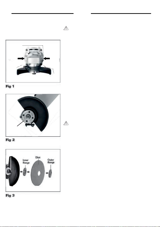
1. INSTALLINGTHEAUXILIARYHANDLE
(seefig1)
Anauxiliaryhandleis suppliedand canbe fixedintobothof
thetwopositionsonthegearcase.If youarerighthanded fit
the handle as shown in fig1. If you are left handed fit the
handletheotherwayround.Whenusingacuttingdisc,you
can screw the handle into the position on top of the
gearcase.
NOTE: This handleshouldbe usedat alltimes tomaintain
completecontrolofthetool.
2. ADJUSTINGWHEELGUARD(seefig2)
Adjust the guard to protect your hands and direct grinding
debris.Loosenthescrew.Positiontheguardat therequired
angle.Thentightenthescrew.
CAUTION: Be sure that the guard is secure before
startingtheanglegrinder.
WARNING:Never use theanglegrinder without the
discguardinplace.
3. FITTING THE DISCS (see fig3)
Placethegrinding/cuttingdiscontopoftheinnerflangeand
overthespindle.Ensurethatitisfirmlylocatedontheraised
sectionof theinnerflange.Seefig3.Locatetheouterflange
overthedisc,makingsurethattheraisedsideisfactingthe
discandisfullylocatedinthecentreholeofthedisc.
NOTE: When clamping thin section metal diamond discs,
the outer flange must be reversed so that the flat/dished
sidescrews against the disc hub.
Pressandholddownthespindlelockbuttonandtightenthe
outer flange using the two pin locking wrench. It may be
necessary to turn the spindletofullylocatethe spindlelock
button.
When the outer flange washer is tight, release the spindle
lockbuttonand removethe wrench.
Screw
Spindle

13|English
4.
SWITCH
(seefig4)
TheOn/OfftriggerswitchissprungintheOFF position.The
anglegrinderisstartedbypushingforwardthe on/offswitch.
See fig 4. To stop the angle grinder, release the on/off
switchanditwillreturntotheOFFposition.
WARNING!
The disc will continue rotatefor a few
seconds after the angle grinder has been switchedoff.
Always wait until the disc has stopped completely before
putting the angle grinder down. Do not attempt to operate
the spindlelock buttonwhile the disc is stillrotating.
5.
TO USE GRINDER
(seefig 5)
Attention: Do not switch the grinder on whilst the disc is in
contact with the workpiece. Allow the disc to reach full
speed beforestarting to grind. Hold your angle grinder with
onehandon themainhandleand otherhandfirmlyaround
the auxiliaryhandle.
Alwayspositionthe guard so that as much of the exposed
disc as possibleis pointing awayfrom you.
Be prepared for a stream of sparks when the disc touches
themetal.
For best tool control, material removal and minimum
overloading,maintainan angle between the disc andwork
surface of approximately 15°-30° when grinding and 10°-
15° When sanding. Exert light pressure on abrasive discs
for efficient operation. Pushing too hard will cause a drop
inspeed andmayresultinmotoroverloadand damage.
Use caution when working into corners as contact withthe
intersectingsurfacemay causethegrinderto jumo or twist,
When grinding is complete allowthe workpieceto cool. Do
nottouchthehotsurface.
6. OVERLOAD
Overloading will cause damage to the motor of your angle
ginder.Thiscanhappenifyouranglegrinderissubjectedto
heavyuseforprolongedperiodsoftime.
Do not in any circumstances, attempt to exert too much
pressureon your anglegrinder to speed up yourwork.
On/off
switch button
15
0
- 30
0

14|English
The abrasive discs operate more efficiently when light pressure is exerted, thus avoiding a drop in
thespeedof youranglegrinder.If yourangle grinderbecomestoohot,runyourangle grinder under
noloadfor2-3minutesuntilithascooledtonormaloperationtemperature.
WORKING HINTS FOR YOUR ANGLE GRINDER
1. Youranglegrinderisusefulforbothcuttingthroughmetals,ie.forremovingscrewheads,andalso
forcleaning/ preparingsurfaces,ie.beforeandafterweldingoperations.
2. Different types of wheel/cutter will allow the grinder to meet various needs. Typically, grinding
wheels/cutting discs are available for mild steel, stainless steel, stone and brick. Diamond
impregnateddiscsareavailableforveryhardmaterials.
3. Ifthegrinderisusedonsoftmetalssuchasaluminumthewheelwillsoonclogandwillhavetobe
changed.
4. At all times,let the grinderdo thework, do not forceit or apply excessive pressureto the
wheel/disc.
5. Ifcuttingaslotensurethatthecutteris keptalignedwiththe slot,twistingthecuttermaycausethe
disc to shatter.If cuttingthroughthin sheet, only allow the cutter to just project through the material,
excessivepenetrationcanincreasethechanceofcausingdamage.
6. Ifcuttingstoneorbrick,itisadvisabletouseadustextractor.
MAINTENACE
WARNING:
Ensurethe grinderis disconnected from the mainspower supplybeofre
attemptinganymaintenance.
1. Keepthegrinderventilation slots clean and free from ocstructions.If available,blow compressed
air into the vents to clear any internal dust (safety goggles must be worn whrn undertaking this
process).
2. Keep the outer case of the grinder clean and free from grease, Do not wash with water or use
solvents or abrasive.Useonly mildsoapand a dampcloth to cleanthetool.Neverletany liquidget
insidethetool.Neverimmerseanypartof thetoointoaliquid.
3. Youranglegrinderrequiresno additionallubrication. Thereare no userserviceableparts inyour
powetool.
4. Alwaysstoreyourpowertoolinadryplace.
5. Ifyouseesomesparksflashingintheventilationslots,thisnormalandwillnot damageyourpower
tool.
TROUBLESHOOTING
Although your new anglegrinder is reallyverysimpleto operate, if you do experience problems,
pleasecheckthe following:
1. Ifyougrinderwillnotoperate,checkthepoweratthemainsplug.
2. Ifyourgrinderwheelwobblesorvibrates,checkthatouterflangeistight,checkthatthewheelis
correctlylocatedontheflangeplate.
3. If thereis any evidencethat the wheel is damaged, do not ues as the damaged wheelmay
disintegrate,removeitand replacewithanewwheel.Disposeofoldwheelssensibly.
4. If working on aluminum or a similarsoftalloy,the wheel will soonbecomecloggedand will not
grindeffectively.
ENVIRONMENTAL PROTECTION
Wasteelectrical productsshould not bedisposedof withhouseholdwaste.Pleaserecycle
where facilities exist.Checkwithyour LocalAuthorityor retailerfor recycling advice.

15|English
AG110018,UAG110018,AG110018-4,AG110018-6,
AG110018-8,AG110018S,AG110018E

16|English
AG110018,UAG110018,AG110018-4,AG110018-6,
AG110018-8,AG110018S,AG110018E
No.
Part Description
Qty
No.
Part Description
Qty
1
Outter flange
1
25
Armature
1
2
Inner flange
1
26
1
3
Wheel guard
1
27
Anti-dust cover
1
4
Screws with washer M4X16
4
28
Bearing 607
1
5
Output shaft
1
29
Bushing
1
6
Dust cover
1
30
4
7
Front cover
1
31
2
8
1
32
Stator
2
9
Bearing 6201
1
33
Housing
2
10
1
34
Insulation washer
2
11
Gear
1
35
Coil spring
2
12
Needle sleeve HK0810
1
36
Carbon brush holder
2
13
Gear box
1
37
Carbon brushes
2
14
Screws ST4x28
4
38
4
15
Pin cap
1
39
Back housing
1
16
Locking spring
1
40
Switch knob
1
17
1
41
Screws ST4X14
4
18
Locking cap
1
42
Pole
1
19
Side handle
1
43
1
20
Nut M6
1
44
Switch
4
21
Pinion
1
45
Cable clamp
1
22
Bearing 629
1
46
Cord guard
1
23
1
47
Power cord
1
24
Middle cover
1
48
Spanner
1

This manual suits for next models
6
Table of contents
Popular Grinder manuals by other brands


Bosch
Bosch GWS 6-100 Professional operating instructions

Universal Tool
Universal Tool UT8706-2 operating instructions

Bosch
Bosch GWS Professional 10-125 Original instructions

HIKOKI
HIKOKI G 3612DA Handling instructions

Parkside
Parkside PFBS 160 B2 Translation of the original instructions

Milwaukee
Milwaukee M18 FUEL 2980-20 Operator's manual


