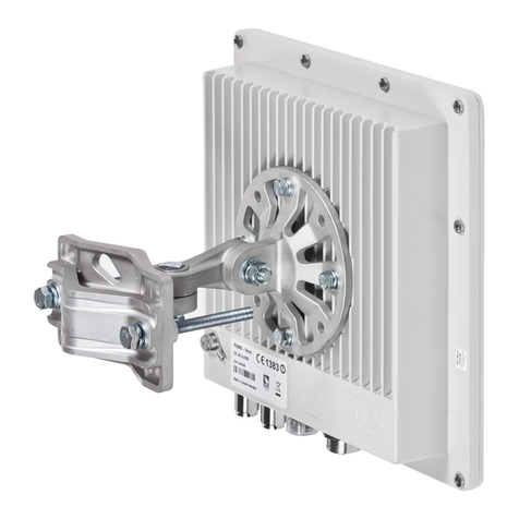
InfiNet Wireless R5000 User manual

Copyright ©2004-2009 byInfiNetWireless Limited. 1
Revisiondate:20 August 2010
InfiNet Wireless R5000
Quick startguide

Copyright ©2004-2009 byInfiNetWireless Limited. 2
LegalRights
©Copyright2010 InfiNetWireless.Allrightsreserved.
Theinformationcontainedinthisdocumentisoriginatedby,proprietary,confidentialandownedby
InfiNetWireless. Nopartofthisdocumentshouldbedisclosed,reproducedordistributedwithoutthe
express writtenpermissionofInfiNetWireless Ltd.
InfiNetWireless Ltd.reservestherighttochangetheinformationcontainedinthisdocumentwithout
prior notice.Nopartofthisdocumentmaybe considered asapartofanycontractor warranty.
StatementofConditions
The informationcontainedinthismanualissubjecttochange withoutnotice.
InfiNetWirelessLtd.shallnotbeliableforerrorscontainedhereinorforincidentalorconsequential
damagesinconnectionwiththefurnishing,performance,oruseofthismanualorequipmentsupplied
withit.
Disclaimer
Thesoftware issoldonan"ASIS"basis.InfiNetWireless,itsaffiliatesoritslicensorsmakeno
warranties,whatsoever,whether expressorimplied,withrespecttothesoftware andtheaccompanying
documentation.InfinetWirelessspecificallydisclaimsall impliedwarrantiesofmerchantabilityandfitness
foraparticularpurposeandnon-infringementwithrespecttothe software.Unitsofproduct(includingall
thesoftware) deliveredtopurchaser hereunder are notfault_ tolerantandare notdesigned,
manufacturedorintendedforuse orresale inapplicationswhere thefailure,malfunctionorinaccuracyof
productscarriesariskofdeathorbodilyinjuryorsevere physicalorenvironmentaldamage(“highrisk
activities”).Highriskactivitiesmayinclude,butare notlimitedto, useaspartofon-linecontrolsystems
inhazardousenvironmentsrequiringfail-safeperformance,such asintheoperationofnuclearfacilities,
aircraftnavigationorcommunicationsystems, airtrafficcontrol,lifesupportmachines, weaponssystems
orother applicationsrepresentingasimilardegreeofpotentialhazard.Infinetwireless specifically
disclaimsanyexpressor implied warrantyoffitnessforhighriskactivities.
InfiNetWireless herebydeclaresthat R5000-Om,R5000-Mm,R5000-Smand R5000-Lmare incompliance
withtheessentialrequirementsandother relevantprovisionsofDirective1995/5/EC.Thedeclarationof
conformitymaybe consulted at
http://www.infinetwireless.com/products-technologies/type-approval-certificates/DoC_RTTE.pdf.
Indicationof thecountries
InfiNetWireless equipmenthasnogeographicallimitationsforsellingandcanbesupplied toanycountry
ofthe world.
Limitationof Liability
InfinetWireless shall notbeliabletothepurchaser ortoanythirdparty,foranyloss ofprofits,loss of
use,interruptionofbusinessorforanyindirect,special,incidental,punitiveorconsequentialdamagesof
anykind,whether arisingunder breach ofcontract,tort(includingnegligence),strictliabilityor otherwise
and whether based onthisagreementor otherwise,evenifadvisedofthe possibilityofsuch damages.
Totheextentpermittedbyapplicablelaw,innoeventshall the liabilityfordamageshereunder ofInfinet
Wireless oritsemployeesoragentsexceedthepurchasepricepaidfortheproductbypurchaser,nor
shall theaggregateliabilityfordamagestoall partiesregardinganyproductexceedthepurchaseprice
paid for that productbythat party(exceptinthe caseofabreach ofaparty’sconfidentialityobligations).
InternationalRegulatoryInformation
Thisequipmenthasbeentested and found tocomplywiththe limitsfor aClassBdigitaldevice.

Copyright ©2004-2009 byInfiNetWireless Limited. 3
Hereby,InfiNetWireless declaresthat thisequipmentisincompliancewiththeessentialrequirements
and other relevantprovisionsofDirective1999/5/EC.

InfiNetWireless QuickStartGuide
Copyright ©2004-2009 byInfiNetWireless Limited. i
Tableofcontents
I. GETTING STARTED.......................................................................................................... 4
1. Scope ofdocument...........................................................................................................4
Getting started..............................................................................................................4
Getting access tothe router............................................................................................4
Point-to-pointconfiguration.............................................................................................4
Other topologies............................................................................................................4
Performing outdoor testing .............................................................................................4
2. Abbreviations...................................................................................................................4
3. Documentmarks..............................................................................................................5
4. Additionalinformation.......................................................................................................5
II. GETTING ACCESS TO THEUNIT...................................................................................... 6
1. PC/Laptop/LANconnection.................................................................................................6
Cabling (lab) .................................................................................................................6
Accessing the unitviaConsole.........................................................................................7
Accessing the unitviaEthernet......................................................................................10
2. Initialsetup....................................................................................................................12
Systemparameters......................................................................................................13
Learning unit’scapabilities............................................................................................13
Radiomodule parametersconfiguration..........................................................................14
III.POINT-TO-POINTCONFIGURATION............................................................................. 15
1. Units’configuration.........................................................................................................15
2. Learning connectionstatus..............................................................................................16
3. Providing IP connectivity..................................................................................................17
Routed link..................................................................................................................17
Switched link...............................................................................................................21
4. Linkthroughputtest........................................................................................................23
5. Simple configurationfor establishing E1radiolink..............................................................23
IV. OTHERTOPOLOGIESCONFIGURATION........................................................................ 26
V. PERFORMING OUTDOORTESTING............................................................................... 27
1. Distance setting..............................................................................................................27
2. Learning linkstatus/antennaalignmentprocedure..............................................................27
AntennaalignmentwithMINTMonitor............................................................................28
AntennaalignmentwithLinktest...................................................................................29

InfiNetWireless QuickStartGuide
Copyright ©2004-2009 byInfiNetWireless Limited.
4
I. GettingStarted
Thisdocumentisdesignedtohelpengineers/techniciansinrapidconfiguringof
InfiNetWirelessR5000system.Thedocumentincludesdetailedinstructionsfor
firstconfigurationstepsandconfigurationscenarios fortypicalnetwork
topologies.
1. Scope ofdocument
Thisdocumentconsistsofthe following chapters:
Gettingstarted
Thischapterincludestheinformationabout thisdocument purposeandstructure.
Gettingaccess totherouter
Thechapterdescribeshow togetaccess totherouterviaConsolePort andto
configureEthernetport.
Point-to-pointconfiguration
Thischapter includesacomprehensivelistofinstructionsforpoint-to-pointlink
configurationincluding providing LANconnectivity.
Othertopologies
Thechapter brieflydescribesthedifferencebetweenconfiguringPTPlinksand
networkswithother topologies.
Performingoutdoor testing
The chapter containsalistofrequirementsfor outdoortesting.Also abasicsteps
for linkimprovementand antennaalignmentispresented.
2. Abbreviations
The following abbreviationsare used inthisdocument:
•BS–Base Station
•CPE–Customer PremisesEquipment(also called subscriber or
subscriberunit)
•ODU–OutdoorUnit
•IDU–Indoor power supplyUnit
•RFcable –RadioFrequencycable toconnectODUand antenna
•LOS–Line-of-Sight
•STPcable–ShieldedTwistedPaircabletoconnectODU andIDU
(relevantfor5000-Oand5000-Mmodifications).FTP(FoiledTwisted
Pair) CAT5e also canbe used
•PTP –Point-to-Pointtopology
•PTM–Point-to-Multipointtopology
•MINT–MeshInterconnectionNetworking Technology

InfiNetWireless QuickStartGuide
Copyright ©2004-2009 byInfiNetWireless Limited.
5
3. Documentmarks
All warningsare markedwithaspecialwarningsign.Oneshouldpay
agreat dealofattentiontowhat iswritteninthe Warning sections.
All notesare markedwithaspecialnotesign.Notesusuallycontain
usefulcommentsor hintstothe described sectionofthe document.
4. Additionalinformation
Additionalinformationwhich isnotincludedinthisManualcanbefoundinthe
following sources:
•Device passportlocated inthe box withthe device
•InfiNetWireless R5000.TechnicalUser Manual
•WANFleXOSUser Guide
•Our web-site: www.infinetwireless.com

InfiNetWireless QuickStartGuide
Copyright ©2004-2009 byInfiNetWireless Limited.
6
II.Gettingaccess totheunit
1. PC/Laptop/LANconnection
Cabling(lab)
Thesequenceofactionstobeperformedinorder toconnecttheunittothe
PC/Laptop isthe following:
1. Unpackthe equipment
2. Ifyoudonothaveaservicecablesoldered,pleasedoitusingspecial
connectorsincludedintothepackageaccordingtothesolderingscheme
located inthe “Supplementaryinformation”section.STP cable cat 5or cat 5E
should be used.
3. LocateIDU(bluecase) andODU(whitecase).UsingSTPServicecable
connectODUandIDU.Servicecablesocketsare markedonthediagrams
below
IDU-5000-SCR
IDU-5000-CPE
Figure 1.IDUsFronts
Figure 2.RJ-45 ODUFront(fragment)

InfiNetWireless QuickStartGuide
Copyright ©2004-2009 byInfiNetWireless Limited.
7
Figure 3.Screw LockODUFront(fragment)
Accessingthe unitviaConsole
Ifyoucannotgetaccesstotheunitusingprocedure describedin“Accessingthe
unitviaEthernet”sectionplease follow the stepsdescribed inthissection.
1. UsingInfiNetConsoleCablepleaseconnecttheunit’sconsoleport(see Fig.
2) tothe COM-portofyour PC/Laptop
Inorder toaccomplishthestepsdescribedinthissectionyour
PC/Laptop mustbe equipped withaCOM-port
2. Locate the power cordinthe package
3. PlugthepowercordintotheIDUpower supplyconnectorandtothepower
supplysocket(220V50Hzor110V60Hzdependingonthecountryof
residence)
4. Greenpower indicator onthe IDUmustlightup
5. Power your PC/Laptop on
Followingstep’sscreenshotsare takenfromMicrosoftWindowsXP.
Youcanalso performthisprocedure inMicrosoftWindows
98/NT/2003
6. Run Hyperterminal.See Figure 4
Figure 4.Locate Hyperterminal
7. Indicateconnectionname(e.g.“IWRLabTest”)andspecifytheCOM-port
name towhich the unitisconnected.See Figure 5

InfiNetWireless QuickStartGuide
Copyright ©2004-2009 byInfiNetWireless Limited.
8
Figure 5.Selectthe port
8. SpecifyportparametersexactlyasshownonFigure 6
Figure 6.Portparameters
9. Ifyouconnectedeverythingproperly,selectedtherightportandmadeits
configurationright,afterpressingenteronthewhiteblankscreen(afterstep
8) youshouldsee WANFleXOSpromptasshownonFigure 7

InfiNetWireless QuickStartGuide
Copyright ©2004-2009 byInfiNetWireless Limited.
9
Figure 7.WANFleXOSprompt
10. Yourdevicehasafactoryconfiguration.That meansthat youcanenter ANY
non-zerolengthloginand password.Once thisisdone,youwillsee WANFleX
CLI(Command Line Interface).See Figure 8
Figure 8.“After login”screen
11. Inorder foryourunittobeaccessiblefromyourLAN/PC/Laptopvia
Ethernet,youshouldconfigure eth0 interfaceIP-address so theunitwould
allocateinthedesiredLAN(oraccessiblefromyourPC/LaptopEthernet
adapter).YourcanchangethisIP-addressvia“ifceth0”commandas
shownonfigure 9.After changingtheIP-address, savetheconfiguration
using“cosa”command.IntheexamplegiventheIP-address being
assignedto eth0 interfaceis 9.1.8.1 withmasklength24 (255.255.255.0).
Inorder tocheckwhether yourchangeswere correct,use“coshifc”
commandwhich showsconfigurationforall interfacesoftheunit.Donot
forgettosaveyour configurationusing “cosa”(configsave) command.
Figure 9.Changing IP-address on eth0 interface
12.Ifallyoursettingsare correctyoucanconnecttheunittoyourLANusing
UTP cable withRJ-45 connectors(Ethernetportoftheunitislocated onIDU).

InfiNetWireless QuickStartGuide
Copyright ©2004-2009 byInfiNetWireless Limited.
10
Accessingthe unitviaEthernet
IfyourPC/LaptopdoesnothaveaCOM-portoryouwanttoplugtheunittothe
LANswitch youcanconfigure itusingTelnetprotocol.
ThedefaultIP-address assignedtothe eth0 interfaceoftheunitis 10.10.10.1
with255.255.255.0mask.
IfyouconnecttheunitdirectlytotheLAN/PC/Laptopyoushouldeither change
theIP-addressontheEthernetadaptororcreateanaliasIP-addresswhich
would be located in 10.10.10.0/24 network.
Connectthe unittoLAN/PC/Laptop usingUTP cable withRJ-45 connectors.
The procedure isthe following:
1. Openthe ControlPanelinWindows.See Figure 10
Figure 10.OpenControlPanel
2. Open“Networkconnections”icon.See Figure 11
Figure 11.“Networkconnections”
3. In“Networkconnections”folder rightmousebuttonclickontheLAN
connectionand click“Properties”.See Figure 12

InfiNetWireless QuickStartGuide
Copyright ©2004-2009 byInfiNetWireless Limited.
11
Figure 12.LANConnectionproperties
4. Choose “Internetprotocol(TCP/IP)”and click“Properties”.See Figure 13.
Figure 13.InternetProtocolProperties
5. IfyouwanttoconnecttotheunitusingPC/Laptopyoucanjustchangean
IP-addressontheEthernetadaptortosomeaddressfrom10.10.10.0/24
network(e.g.change“IP-address”fieldto“10.10.10.2”and“Subnetmask”
to“255.255.255.0”).After that click OK and move tostep 7.See Figure 14
Figure 14.ChangeIP-address
6. Ifyouare inaLANandyoudonotwanttochangeyourprimaryIP-address
so youcouldkeepLANconnectivity,youcanassignanalias.Inorder todo
that,press “Advanced…”button(Figure 14).In“AdvancedTCP/IPSettings”
click“Add”andputaliasIP-addressandmask(e.g.“10.10.10.2”and
“255.255.255.0”correspondingly).See Figure 15.Click OK inall windows
opened inthe described procedure.

InfiNetWireless QuickStartGuide
Copyright ©2004-2009 byInfiNetWireless Limited.
12
Figure 15.Create alias
7. Run “Telnet”utilityusing“Start->Run”andtype“telnetIP-address”where
IP-address isthe unit’sIP-address (bydefault:10.10.10.1).
8. FollowSteps9to11 of“AccessingtheunitviaConsole”sectioninorder to
change the IP-address onthe eth0 interface ofthe unittothe desiredone.
2. Initialsetup
Onceyouhavegottheaccess totheunitviaTelnet,youcanperforminitialunit
setup.Run telnetapplication(Start->Run)usingIP-address thatwasassigned
onthe eth0 interface ofthe unit(for example,9.1.8.1)
Firstofall,letuslistsome usefulcommandsthat should be remembered.
•“help”–listsall available commandsinthe unit
•“configshow”(or“cosh”forshort)–showsunit’scurrent
configuration
•“configsave”(or“cosa”for short)–savesunit’scurrentconfiguration
•“restarty”–immediateunitreboot.Rebootlastsfor20-30seconds
(approximately)andduringthistimeyouwillnotbeabletocontrolit
over Telnet.“restartXX”canbeusedforapostponedrebootso the
unitwillberebootedinXX seconds(thisisveryhelpfulwhenthere isa
riskofloosingaremoteunitwhileperformingrisky manipulationswith
configuration).“restart0”cancelspostponed reboot.
•“quit”–closescurrenttelnetsession
Themaximumnumber ofconcurrentTelnetsessionsper oneunitis
five.

InfiNetWireless QuickStartGuide
Copyright ©2004-2009 byInfiNetWireless Limited.
13
System parameters
Onceyou’vegotaccess totheunit,themostcommonthingtobedoneinthe
firstturnistosetup some basicsystemparameters:
•Systemname.Systemname isspecified bythe following command:
system name [system_name]
•Systemuser.Thisparameter will be used asalogin:
system user [user_name]
•Systempassword.Systempasswordisused asapassword whilelogin:
system password[password]
•Systemprompt.Thiscommandwill changecurrentcommandline
interface prompt:
system prompt [any_word]
Also,itmaybeusefultoknowfirmwareversionthat iscurrentlyavailableinthe
unitandunit’sserialnumber.“Sysver”commandcanbeusedforthispurpose
(Figure 16):
Figure 16.Systemversion
Learningunit’scapabilities
1. Inordertolearncurrentinterfacesconfiguration,execute“coshifc”
command
2. Inorder tolearnall configuredinterfaces, theirstatesandstatistics, execute
“ifc–a”command.See Figure 17.
Figure 17.Interfacesinformation
Notethat radiointerfacenamemaydiffer from“rf4.0”dependingonthe
model’sfrequencyrange(2.4GHzor5GHz)andnumber ofradiomodulesin

InfiNetWireless QuickStartGuide
Copyright ©2004-2009 byInfiNetWireless Limited.
14
thedevice(oneortwo).Anyway,radiointerfacenamealwaysstartswith
“rf”.
Informationonthespecificinterfacecanbeobtainedusing“ifc<IF-
NAME>”command.Forexample,“ifcrf4.0”will giveyouinformationon
“rf4.0”interface.
3. Inorder togetunit’scapabilitiesincludingavailablefrequencylist,transmit
power levels,bitratesforthespecificradiointerface,“rf<IF-NAME>cap”
command isused.For example,“rfrf4.0cap”.See Figure 18.
Figure 18.Unit’scapabilities
Radiomodule parameters configuration
1. Power levelchanging isaccomplished using “rf<IF-NAME>pwr<power-
level>”command.Forexample,“rfrf4.0pwr32”setstransmittingpower
levelto32mW.Power levelspecifiedinthecommandshouldbetheone
fromthe listofavailable power levels.
2. Frequencychangingisaccomplishedusing“rf<IF-NAME>freq
<frequency>”command.Forexample,“rfrf4.0freq5340”setscurrent
workingfrequencyto5340 MHz.Atthesametimeoneradiomodulecan
workonlyonONEfrequency.
3. Bitratecanbechangedusing“rfrf4.0bitr<bitrate>”command.For
example,“rfrf4.0bitr 24000”setscurrentbitrate to24 Mbps.

InfiNetWireless QuickStartGuide
Copyright ©2004-2009 byInfiNetWireless Limited.
15
III.Point-to-Pointconfiguration
Inourpoint-to-pointconfigurationexamplewe will builtasimplenetworkas
showninFigure 19a.
Figure 19a.Sample network(PtP connection)
Pleasenotethat InfiNetWirelessunitisabletoworkbothinroutingand
switchingmodes.Thisparticularexampleexplainshowtoconfigure aPTPlinkin
a router mode.
Here we willsetup aconnectionbetweentwoPC/Laptops.
All configurationsamplesandnoteswilluseIP-addressesandnames
asspecified inFigure 19a.
1. Units’ configuration
1.ChooseoneoftheunitstobeCPEandtheotheronetobeBS.InPTPlinkit
makesnodifference which unitwill take what role.
2.ProvideconnectivityfromPC1toCPEandPC2toBSfollowingtheprocedure
describedin“Gettingaccess totheunit”.Asaresultyoushouldmakesure that
youcanping/telnetCPEfromPC1and ping/telnetfromPC2
3.Nowwe willproceedtounits’configuration.FromPC1enter CPEunitusing
Telnet(Start->Run:“telnet9.1.8.1”)andfromPC2enter BSunit(“telnet
9.2.8.1”)
4.Nextstepisconfiguringradioparametersoftheradios. Asthepurposeofthis
documentistoshow the basicsettingswe onlywillcover essentialparametersof
theradioso that theconnectioncouldbeestablished.Infact,radiohasmany
more other settingsnotmentioned below:
•Unitsshould be configured for the same frequency.Example:
rfrf4.0freq5200
•Setupoutputpower.Forlabtestingpurposesthepower canbe
configured at the minimalvalue.Example:
rfrf4.0pwr 4
•UnitsshouldhavesameSID.SIDcanbechosenasany8-digitHEX
number.Example:
rfrf4.0sid11223344
•Setup desired working bitrate.Example:
rfrf4.0bitr 24000
Pleasenotethat thelistofallowedbitratescanbe viewed using“rfrf4.0
cap”commandandmaydependontheunit’smodificationandselected
channelwidth(these settingsare notwithinthe scopeofthisdocument).
5.After radioconfigurationsare done,we needtorun MINTprotocolwhich isa
core ofInfiNetWirelessunit’sarchitecture.Onbothunitsthefollowingcommand
should be executed:
mintrf4.0start

InfiNetWireless QuickStartGuide
Copyright ©2004-2009 byInfiNetWireless Limited.
16
Ifradiosettingsare doneproperlyandunitscanphysically“hear”each other,
theunitswill exchangeaseriesofservicepacketsandestablishaconnection.In
order tocheckit,one should use acommand “mintmap”.
Also,the following configurationsmaybe made inour particular PTP scenario:
•Setup aname for anetworknode (fromMINTstandpoint).Example:
mintrf4.0–name“Test_Node_1”
•Setupnodeid(nodesin“mintmap”will sortedaccordingtothis
numericalparameter):
mintrf4.0–nodeid1234
Inorder tosee currentMINTprotocolconfiguration,use“coshowmint”
command.
2. Learningconnectionstatus
Onceallconfigurationstepsare correctlyperformedyoushouldmakesure that
the connectionisestablished.
Pleasekeepinmindthat onceMINTprotocolisworkingonMAC-layer (2nd layer
ofOSI)IP-connectivityneedstobeconfiguredafter linkconnectivityis
established.
Actually,itmakesnosensetoconnectantennastothedeviceswhilelabtesting
butstillyouneedtomakethem“hear”each other.Also youmaytryinserting
somekindofsteelpaper-clipintheconnector–thismighthelpinsignal
improvement.
Inorder tolearncurrentconnectionstatus,“mintmap”commandshouldbe
used.
Example of“mintmap”command output:
Figure 20.“mintmap”command
InourPoint-to-Pointscenario,we willbehavingonlyoneneighbor(inMINT
protocolterminology) fromeither side ofthe link.
What importantinformationdowe learnfrom“mintmap”output:
1. Thelistofcurrentunit’sneighborsforoneormore radiointerfaces(here in
oursimple scenariowehave onerf4.0interfaceand oneneighborasthe link
ispoint-to-point)
2. Costparameter isonethemostimportantparametersinMINTarchitecture
asitdefinesthebaseuponwhich all theroutesinMINTnetworkare
calculated.Butinpoint-to-pointscenariothisparameter isofaless

InfiNetWireless QuickStartGuide
Copyright ©2004-2009 byInfiNetWireless Limited.
17
importanceasMINTdoesnothavetolookforotheralternativeroutesto
send apacketto
3. Input/Outputsignallevels.Here,theparametersare displayedindBabove
currentnoisethresholdswhich are definedbycurrentbitrates(displayedon
therightfromsignallevels).Whatisagoodsignallevel(forcurrent
bitrate)?Forlower bitrates(equalorless than24 Mbps)signallevelshigher
than12-14 dBcanbeconsideredacceptable.Forhigher bitratesitis
recommended tohave higher signallevels(>20 dB) inorder tohave astable
connectiononthisbitrate and less retriesand errors.
4. Typeofnode:master,meshorslave.Withoutgoingdeepintodetails(as
thisisnotthe purposeofthisdocument),the followingmustbe mentioned:
a. Inorder tocreatePTPlink,unitsshouldbeconfiguredeither in
“mesh”mode(bothunits)oroneshouldbe“master”andanother
one“slave”.Inthesecondcaseanon-collisionpollingprotocolcan
be enabled onthe “master”unit.
b. InPoint-to-Multipointlink,BaseStationshouldbeconfiguredas
“master”and CPEsas“slaves”.
3. ProvidingIPconnectivity
Once we have connected our twounitsinaPoint-to-Pointlink,the nextstep isto
configure IP-connectivity.
Unitscanbeconfiguredineither router orswitch modeoreveninhybridmode
combining router and switch functionality.
Inthismanualwe willreviewtwomostsimplecasesoflinkconfigurationin
router and switch mode.
Routedlink
Inthesimplestcase,thefollowingshouldbedonetocreateroutedlink(see
Figure 19,pg 13 for IP-addressesconfiguration):
1. Configure twounits’eth0(physicalEthernet)interfacetoadifferentnetwork
subnets. Inourexampletheaddressesare 9.2.8.10/24(9.2.8.0/24network)
and 9.1.8.10/24 (9.1.8.0/24network).Command example:
ifceth09.1.8.1/24
Pleasenotethat after executingthiscommandyouwillloosetheconnection
toyourcurrenttelnetsession(asyouhaveloggedonusingdifferentIP-
address)andyouwillneedtore-logtotheunitandsavetheconfiguration
withanew IP-address(“cosave”commandsavesthe configuration).
2. Nextstepistoconfigure asubnetbetweentworadiointerfaces. Inour
exampleweuse10.10.10.0/30network.Oneunit’sradiointerfacegets
10.10.10.1addressand another one gets10.10.10.2address. Example:
ifcrf4.010.10.10.1/30
3. After configuringIP-addressesyoucanpingtheoppositesideofthelink
using addressesassigned toradiointerfaces.
4. Next,we needtoconfigure routingbetweenourtwosubnetswhich are
9.2.8.0/24 and9.1.8.0/24.Onecanusestaticordynamicrouting(RIPor
OSPF).Youcan,forexample,justenableRIPprotocolonbothunits(“rip
start”command)orusestaticrouting.E.g.onthefirstunitwhich has
9.1.8.1/24 addressoneth0(Ethernet)and10.10.10.2/30ontheradio
interface (rf4.0) the command will lookasfollows:
routeadd 9.2.8.0/24 10.10.10.2

InfiNetWireless QuickStartGuide
Copyright ©2004-2009 byInfiNetWireless Limited.
18
which will meanthat thenetwork9.2.8.0/24 isaccessiblevia10.10.10.2
address.
Atthispoint,youcanreach (e.g.ping)remote’s eth0 interfacebothfrom
one unittoanother.
Figure 21.Pinging remote’sEthernet
The nextstepistomake youLaptops/PC/LAN“see”each other.
IfyouconnecttwoPC/Laptops(forexample,Windows-basic)twooptionsare
availableinthiscase:
1. WritearoutetothecorrespondingEthernetnetworkat theoppositesideof
thelink.Inorder todothis, go“Start->Run”andrun“cmd”–Command
Line.Atthe BScomputer youshould write the following:
routeadd 9.1.8.0mask 255.255.255.09.2.8.1
ThismeansthatwhenanIP-packetgoesfromthecomputer connectedto
yourBSdevicetothecomputer at theCPEside,itwill gototheBSEthernet
interface.Intheunit,accordingtotheroutingtablesformedusingRIP
protocol,thepacketwillbesentviaradiototheCPEunit.Afterthat,CPE
unitwilllookupinitsroutingtablesandsendthepacketthroughits
Ethernetinterface tothe remote computer.
AttheCPEcomputer youshouldperformsimilaractions. Go“Start->Run”
and run “cmd”command.Type the following:
routeadd 9.2.8.0mask 255.255.255.09.1.8.1
Now we provided connectivitybetweentwocomputers.
All routesinWindowsthat are specifiedusing route commandhave
power until nextrebootofthecomputer (specialparameter “-p”
shouldbeusedtomakearoutepermanent).Tosee theroutingtable
inWindows“routeprint”command should be used.
2. Thesecond optionistospecifya defaultgateway forthePC/Laptopwhich
isgoingtobean Ethernet interfaceoftheconnectedunit.Youcanspecify
defaultgatewayparameter inthewindowshownonFigure 14.Pleaserefer.
For the BSside itwillbe 9.2.8.1,for CPE– 9.1.8.1
Inorder tomakesure that yourPC/Laptopsare connected,youcanpingone
side fromthe other one.For example,fromone PC/laptop (located at one side of
the link) we are pinging remote computer at theopposite side (Figure 28)
Figure 22.Pinging remote computer

InfiNetWireless QuickStartGuide
Copyright ©2004-2009 byInfiNetWireless Limited.
19
IMPORTANTHINT!
IP-packetsoriginatedfromtheunititself(e.g.ping,telnet,FTP,SNMP) are
assignedanIP-address(primary)oftheinterfacethroughwhich theyleavethe
unit.Inorder forall IP-packetshave onedefinedIPsourceaddress thefollowing
command canbe used:
sysOfficialAddressIP
Here,“IP”istheOfficialAddress ofthe unitshould bespecified which willactas
asource IP address for all the packetsoriginated fromthe unit.
Other manuals for R5000
2
Table of contents
Other InfiNet Wireless Wireless Router manuals
