Infrico Lab Care Plus CLF50086 Dimensions and installation guide

Ultra Low Chest Freezer
Lab Care Plus (-86ºC)
User Manual and Warranty


1
MAN-U-CLF86-EN Revisi0n: 03 16/02/2023
CONTENTS
1INTRODUCTION............................................................................................................................................ 3
1.1 Intended Use ........................................................................................................................................... 3
2SAFETY INSTRUCTIONS................................................................................................................................. 4
2.1 Symbols ......................................................................................................................................................... 5
2.2 Temperature Monitoring............................................................................................................................... 5
2.3 Initial Charge.................................................................................................................................................. 5
3LABELLING.................................................................................................................................................... 6
3.1 Technical label ......................................................................................................................................... 6
4RECEIPT AND INSPECTION............................................................................................................................ 6
5INSTALLATION .............................................................................................................................................. 7
5.1 Location ................................................................................................................................................... 7
5.2 Environmental conditions of operation................................................................................................... 7
5.3 Environmental conditions for transportation and storage...................................................................... 8
5.4 Unpacking ................................................................................................................................................ 8
5.5 Electrical Connection ............................................................................................................................... 8
5.6 Battery ..................................................................................................................................................... 9
5.7 Levelling..................................................................................................................................................10
5.8 Rubber Gasket ........................................................................................................................................10
5.9 Body Construction (Special Insulation)..................................................................................................11
5.10 Pressure Compensation Valve ................................................................................................................11
5.11 Remote Alarm Installation......................................................................................................................12
5.12 Final Check-up ........................................................................................................................................12
5.13 Cleaning and Disinfection .......................................................................................................................12
6DIGITAL CONTROL PLUS ............................................................................................................................. 13
6.1 Preliminary signs.....................................................................................................................................13
6.2 Commissioning the Device......................................................................................................................13
6.3 Turning the device ON/OFF ....................................................................................................................14
6.4 The display screen ..................................................................................................................................15
6.5 Set Point setting......................................................................................................................................16
6.6 Battery Status .........................................................................................................................................16
6.7 Temperature chart..................................................................................................................................16
6.8 Switching interior light on/off ................................................................................................................17
6.9 Mute alarm .............................................................................................................................................17
6.10 Historical Data Download .......................................................................................................................18
7SETTINGS.................................................................................................................................................... 19
7.1 Main MENU ............................................................................................................................................19
7.1.1 Set Point setting..................................................................................................................................... 19
7.1.2 Battery status......................................................................................................................................... 19
7.1.3 Alarm/Data History Menu ..................................................................................................................... 20
7.2 Alarms setting.........................................................................................................................................23
7.3 'User Identification' Function .................................................................................................................23
7.4 Language.................................................................................................................................................24
8SERVICE MENU........................................................................................................................................... 25
8.1 Date / Time setting .................................................................................................................................25
8.2 Probe Data Readings...............................................................................................................................25
8.3 Alarms list ...............................................................................................................................................25
8.4 Unit name ...............................................................................................................................................25
8.5 Welcome page........................................................................................................................................26
8.6 Advanced functions ................................................................................................................................26
8.6.1 Product / Chamber Probe Calibration ................................................................................................... 26
8.6.2 Output test ............................................................................................................................................ 27
8.7 Parameters .............................................................................................................................................27
9TEMPERATURE MONITORING.................................................................................................................... 28
9.1 Set Point Control.....................................................................................................................................28

2
MAN-U-CLF86-EN Revisi0n: 03 16/02/2023
10 ALARMS...................................................................................................................................................... 28
10.1 Alarms.....................................................................................................................................................28
11 MAINTENANCE, CLEANING, AND CARE...................................................................................................... 33
11.1 Cleaning Procedure.................................................................................................................................33
11.2 Battery replacement...............................................................................................................................35
11.3 Spare Parts and Technical Support .........................................................................................................36
12 TROUBLESHOOTING................................................................................................................................... 37
13 USEFUL LIFE OF THE EQUIPMENT .............................................................................................................. 39
13.1 End of useful life .....................................................................................................................................39
14 TEMPERATURE CHART RECORDER (OPTIONAL)......................................................................................... 40
15 CO2 BACKUP SYSTEM (OPTIONAL)............................................................................................................. 41
16 WARANTY................................................................................................................................................... 43
16.1 Waranty Certificate.................................................................................................................................44
3
MAN-U-CLF86-EN Revisi0n: 03 16/02/2023
1INTRODUCTION
Ultra low Temperature equipment is designed to maintain a temperature between -40°C (-40°F) to -
86°C (-122,8°F) with safety in an environmental environment between 15°C (59°F) and 30°C (86°F), only when
the equipment is used for storage.
Ultra Low Temperature equipment are classified as CLASS I (Protection against electric shock) and have
a CONTINUOUS OPERATION mode according to the standard UNE_EN_60601.
This product has been manufactured under strict quality controls and meets all the requirements
established by Infrico. Each unit has been tested and its quality is ensured before being shipped. This equipment
has been manufactured with recyclable materials, by means of an environmentally friendly production process.
Temperature range of the equipment: -40ºC to -86ºC (-40°F to -122.8°F)
Accuracy: ± 0,1ºC (± 0,2°F)
Display error values: ± 0,2ºC (± 0,4°F)
Please read this manual carefully before installing your new device to become familiar with all of its
advantages.
OBLIGATION! This device must be used only for the purpose described in this manual.
The ultra low freezers described in this manual are high performance units for professional use. These
products are intended for use as cold storage in research and as a general laboratory freezer, storing samples or
inventories at operating temperatures between -40°C (-40°F) y -80°C (-122.8°F)
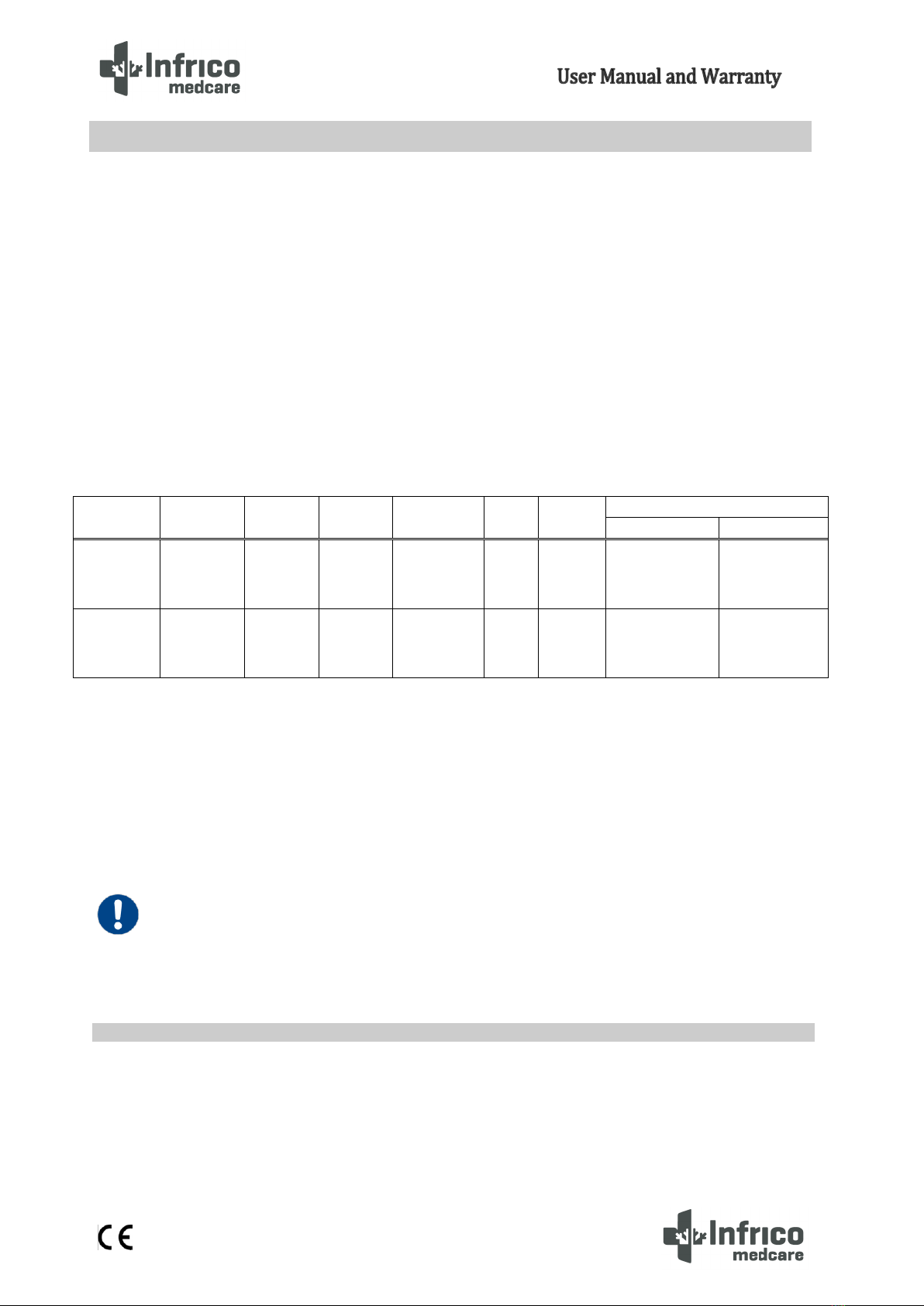
Model
Voltage/
Frequency
Intensity
(A)
Capacity
(l)
Type
Door
Shelves
Dimensions L x W x H
Interior
Interior
CLF50086
230/50
230/60
115/60
5,8
5,8
11,31
500
Horizontal
Solid
-
1190x640x756
2011x954x1092
CLF70086
230/50
230/60
115/60
7,5
7,5
14,63
700
Horizontal
Solid
-
1470x640x756
2291x954x1092
1.1 Intended Use

4
MAN-U-CLF86-EN Revisi0n: 03 16/02/2023
It is not considered a medical device and, therefore, has not been registered with a regulatory body of
medical devices, that is, it has not been evaluated for the storage of samples for diagnostic use or for the
samples to be reintroduced into the medical device body. This unit is not designed for use in unclassified
hazardous locations or for the storage of flammable elements.
WARNINGS: This unit is not a fast freezing device. Freezing large amounts of liquid or high water
content elements will temporarily increase the temperature of the chamber and cause the
compressors to run for a prolonged period of time.
Avoid opening the door for extended periods of time as the temperature of the air chamber will
increase rapidly. Also, keep the interior doors closed as much as possible. When ambient air, which is
more humid, replaces the air in the chamber, the creation of ice can develop in the chamber more
quickly.
In this manual and on the labels of this product, the terms Warning and Caution convey the following
meaning:
•Warning: A potentially hazardous situation which, if not avoided, could result in serious injury or death.
•Caution: A potentially hazardous situation which, if not avoided, may result in minor or moderate injury or
damage to equipment.
Please read this manual and the product labels carefully before installing or using this product. Failure
to follow these instructions may cause the product to malfunction, which may result in injury or damage.
The use of electrical devices implies the implementation of basic safety instructions such as:
•Follow the recommendations in this manual to properly locate and place this device prior to installation.
•Do not allow children to handle the device, as they could damage it, or themselves, seriously.
•Do not touch the cold surfaces of the freezing devices, as such surfaces may adhere to skin.
•Do not store or use flammable products near the device.
•Unplug the device before any cleaning, repair or maintenance operation.
WARNING!: Any manipulation of the device must be carried out by an authorised technical support
service provider.
WARNING!: 'No modification is permitted on this equipment.'
2SAFETY INSTRUCTIONS

5
MAN-U-CLF86-EN Revisi0n: 03 16/02/2023
WARNING!: We inform you that the person installing the device is responsible for carrying out the
installation as instructed in the user manual.
WARNING!: We remind you that you are responsible for the proper maintenance of the equipment.
The manufacturer is not to be held liable for issues resulting from improper maintenance.
WARNINGS
OBLIGATION
PROHIBITION
BATTERY
GROUNDING
NEED TO USE GLOVES
LOW EXTREME TEMPERATURE
Important note: We recommend the use of a redundant and independent temperature monitoring
system, so that the ultra low freezer can be continuously monitored for a performance commensurate
with the value of the stored product.
Allow the freezer to operate at the desired temperature for a minimum of 12 hours before loading.
2.1 Symbols
2.2Temperature Monitoring
2.3Initial Charge
6
MAN-U-CLF86-EN Revisi0n: 03 16/02/2023
Caution Failure to follow these procedures or overloading the unit can cause excessive stress on the
compressors or jeopardize the safety of the product.
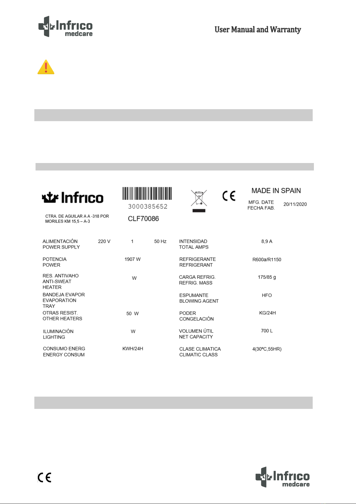
In our equipment, labels are attached to the inside of the products. Their exact location is the top inner
left side.
•All Infrico products are factory tested to assess their quality and performance and are shipped free of defects.
•When you receive your device, it should be carefully examined for any damage that may have incurred during
transportation.
3LABELLING
3.1 Technical label
4RECEIPT AND INSPECTION

7
MAN-U-CLF86-EN Revisi0n: 03 16/02/2023
•If any damage is detected on the unit, you must retain all packaging material and report such damage on the
carrier's bill of lading. A claim must be immediately made to the transport company.
•If the damage is found during or immediately after installation, contact your distributor immediately.
WARNING: Infrico shall not be held liable for damages incurred during transportation.
This device is intended for indoor use only.
Ensure that the location chosen for your equipment has adequate air circulation to ensure efficient
refrigeration.
Avoid locations near heat sources, such as sunny windows, ovens, heaters, as well as direct solar
radiation where temperatures can reach extreme values. In addition, do not choose a location in areas where
temperatures drop below 12°C or rise above 32°C.
Install the ultra low freezer in a level area free of vibrations with a minimum of (20 cm) of space on the
sides and (15 cm) on the back. The doors must be able to open a minimum of 90° in order to use the maximum
available door width.
The surface of the final location where the device is to be placed must be strong enough to support the
total weight of the device considering its full maximum load capacity. In addition, it must be levelled and free of
vibrations. Reinforce the flooring if necessary.
WARNING: Make sure the device is placed in such a way it is easy to operate on the disconnection
device (peg of the power cable).
Ultra-Low Temperature equipment are designed to be safe under the following conditions.
•Indoor use
•Altitude up to 2000 m (795 mbar)
5INSTALLATION
5.1 Location
5.2 Environmental conditions of operation.

8
MAN-U-CLF86-EN Revisi0n: 03 16/02/2023
•Temperatures from 12ºC to 32 ºC
•Maximum Relative Humidity: 60 %
•Voltage fluctuations in mains of up to ±10 % of the nominal voltage.
Ultra-Low Temperature equipment are designed to be safe under the following transportation
conditions.
•Storage temperature: from -15 °C (5°F) to 55 °C (131°F)
•Relative humidity: 20 - 85 % (non-condensing)
The devices are shipped from the factory on a wooden pallet and are packed in sturdy wooden/carton
boxes. The box is screwed to the wooden base. The screws must be removed prior to unpacking to avoid
damage to the unit.
All packaging materials are environmentally friendly and should be reused or recycled. Actively
contribute to the protection of the environment by demanding recyclable packaging and environmentally
friendly disposal methods.
To make easier the unpacking, a ramp is included within the wooden base.
WARNING: Infrico does not recommend knocking the unit forward, sideways, or backward. However,
if this occurs, you must ensure that the unit remains in an upright position for at least 24 hours
before connecting it, so that the compressor oil returns to the compressor.
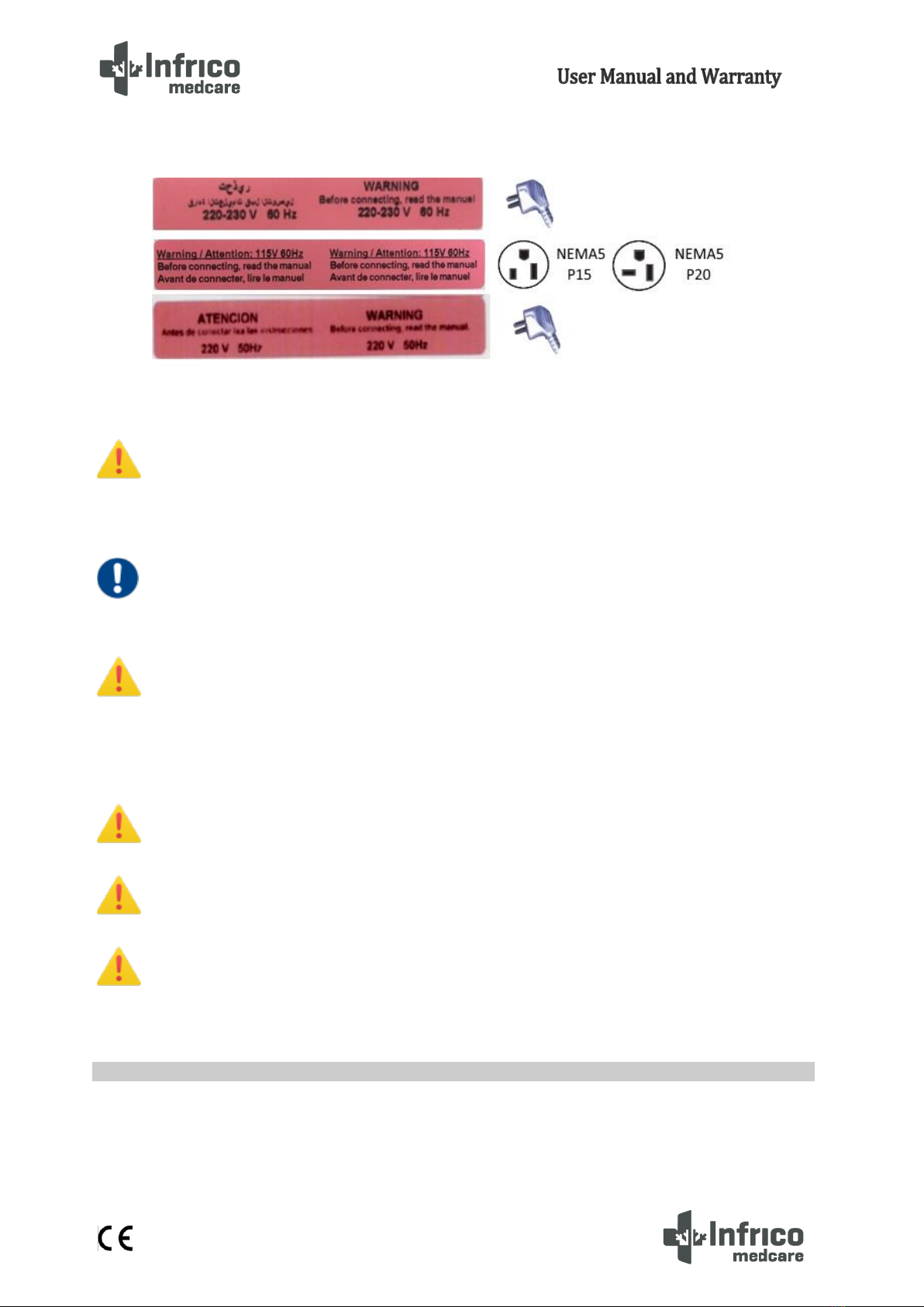
WARNING!: Connect the equipment to a dedicated outlet with the correct voltage for the device.
Incorrect power or voltage fluctuations can cause serious damage to the equipment.
The equipment is prepared for a feeding of the mains 220-230V 50 Hertz, 220-230V 50 Hertz, 115V,
60Hz. The equipment counts on installed hose and pin in factory. Review the adhesive located in the
5.3 Environmental conditions for transportation and storage
5.4 Unpacking
5.5 Electrical Connection
9
MAN-U-CLF86-EN Revisi0n: 03 16/02/2023
feeder. If it does not count on the taking of suitable current, must install it previously. The average one
to isolate the equipment of the feeding network is the pin of the feeder.
WARNING!: This unit must be grounded before use in order to ensure personal safety and the proper
operating of the equipment. A grounding fault may cause damage to personnel or equipment.
Always comply with the National Electrical Code. Do not connect the equipment to power lines that
are already overloaded.
OBLIGATION: The device must be connected to an exclusive dedicated circuit. Failure to comply with
this requirement shall void the warranty.
WARNING!: The device is designed to tackle a voltage fluctuation of around 10 % in relation to the
rated voltage indicated in the rating plate. A compressor fault due to higher fluctuations shall
automatically void the warranty.
Note: It is recommended to install a UPS (Uninterruptible Power Supply) or other system to avoid
voltage peaks or lack of electric current supply.
WARNING!: If the hose or the peg are altered in any way, they may constitute a serious hazard. Any
alteration of these components shall void the warranty.
WARNING: Devices connected to an extension cord are not covered by Infrico's warranty.
WARNING: The power cable can only be replaced by an authorized technical support service
provider.
The equipment is equipped with a 12V-12Ah rechargeable lead-acid battery. Once the equipment has been
installed, it must be connected by an approved installer.
5.6 Battery
10
MAN-U-CLF86-EN Revisi0n: 03 16/02/2023
WARNING!: For battery replacement information, see section 11.2.
It is very important that the apparatus perfectly is made level for a correct operation, so that the water-
drainages drain correctly, the doors are aligned, and the unit is not put under illegal tensions.
In this case, it must make sure that the ground where the unit is located is at level. In order to be able
to work of stable form, to adjust to the legs leg to make sure that the equipment stable and is made level.
To verify that the door is sealed, follow the steps below:
1. Opening the door.
2. Insert a strip of paper between the rubber gasket and the rubber gasket profile, and close the door.
3. Slowly remove the paper strip from the outside. While doing so, you should feel a little resistance.
4. Repeat this operation at 10 cm intervals covering the entire door frame. If the door does not close
properly, the gasket needs to be replaced or the door needs to be adjusted.
CAUTION! Hermetic door sealing is essential for ultra low freezer to function properly. Faulty sealing
allows humid air inside the device, which results in the accumulation of moisture in the evaporator,
resulting in poor temperature maintenance, increased operating time, and increased operating costs.
5.7 Levelling
5.8 Rubber Gasket
11
MAN-U-CLF86-EN Revisi0n: 03 16/02/2023
All the equipment of ultra low temperature has 120mm of insulation core encapsulated by a sealed film
laminate. In the case of CLF, only 120mm of insulation.
Be careful, never drill holes in or near the walls of the body. The perforation could damage the
vacuum and make the unit inoperable.
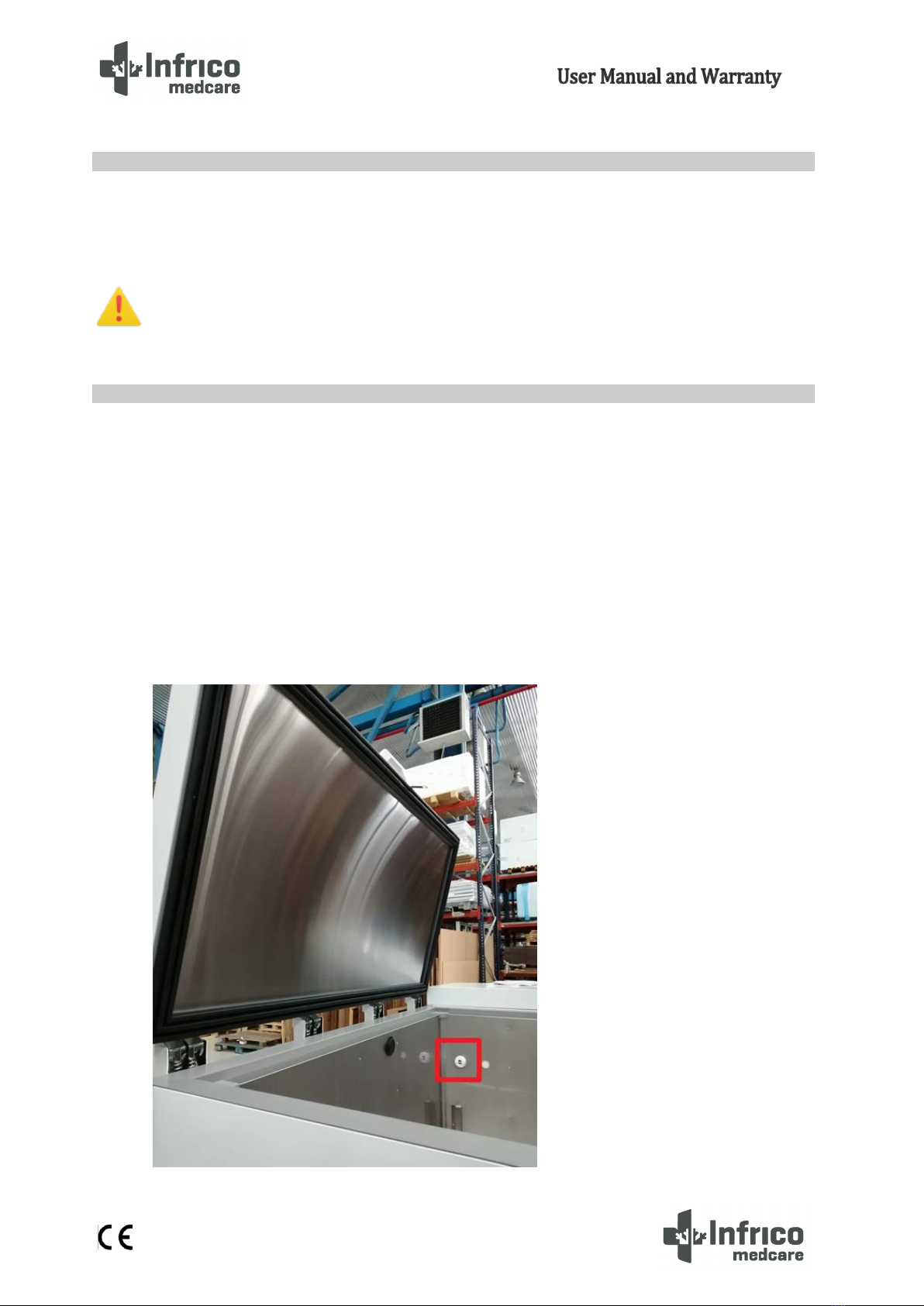
When an outer door of the ultra low freezer is opened at low temperature, the air at room temperature
quickly enters the interior. When the door closes again, the volume of air at room temperature cools down
quickly, dropping the pressure below atmospheric pressure, resulting in a considerable vacuum. The opening of
the outer door is impossible until the internal pressures return to atmospheric pressure. Without a pressure
equalizing mechanism, it can take, in extreme cases, several hours before the door can easily reopen.
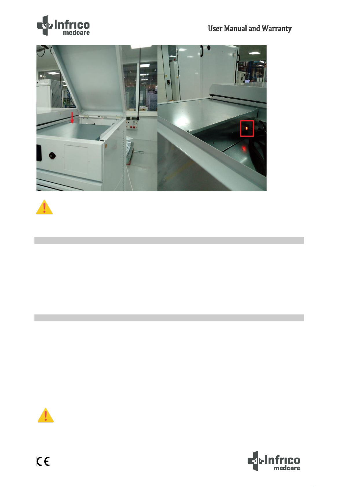
All ultra low temperature equipment has a valve that provides vacuum relief after the door openings.
See the picture below to check the location of the pressure compensation valve.
5.9 Body Construction (Special Insulation)
5.10 Pressure Compensation Valve

12
MAN-U-CLF86-EN Revisi0n: 03 16/02/2023
All ultra freezer models have a remote alarm connection that is located in the back
of the equipment.
Before commissioning the device, follow the steps below:
1. Make sure the unit is free of all wood or cardboard packaging materials, both on the inside and
outside.
2. Verify that the unit is connected to a dedicated outlet.
Before commissioning the device, clean and disinfect it to remove any metal, plastic, sticker or residue
left. Use water with a neutral detergent and dry properly.
CAUTION! Do not use a brush, acid, diluent, laundry soap, washing powder or boiling water to clean
the device.
These may damage the painted surface, as well as the stainless steel surface, or the plastic and
rubber components. Also, do not clean plastic and rubber components with a volatile material.
5.11 Remote Alarm Installation
5.12 Final Check-up
5.13 Cleaning and Disinfection
13
MAN-U-CLF86-EN Revisi0n: 03 16/02/2023
By 'operation mode' we mean the following modes:
o'ON' mode (the device is turned on and the regulators can be turned
on)
o'Stand-by' mode (the device is turned on and the regulators are turned
off)
o'OFF' mode (the device is not turned on)
'Turn on' means switching from 'stand-by' to 'ON' mode. 'Turn off' means switching from 'ON' mode to
'stand-by' mode.
Each time the device is connected to the power supply, it will return to the mode it was in at the time of
disconnection.
Operate as follows:
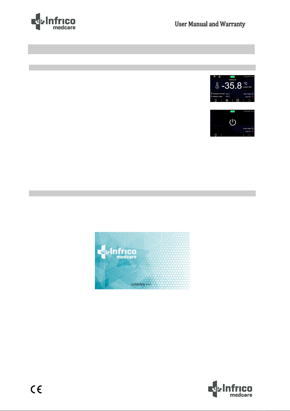
1.- Connect the device to the power source: A 'loading' message will be displayed on screen for a few seconds.
2.- Switch on the main red switch that turn on/off the supply and battery. It is located in the lower grid.
3.- The device will be on 'stand-by' mode, and the date and time will be displayed on the screen. If the controller
is stored for longer than the backup battery capacity, the date and time will require resetting.
6DIGITAL CONTROL PLUS
6.1 Preliminary signs
6.2 Commissioning the Device
“ON”Mode
“Stand-By”Mode

14
MAN-U-CLF86-EN Revisi0n: 03 16/02/2023
4.- Press the ON / STAND-BY icon The home screen will be displayed as shown in the image. The
default code is: 0000.
-If “BLACKOUT”warning is shown:
To make disappear the warning, press the text « Blackout » and go back to the main screen. it is shown to advise
to the user that there was a power fault. It is completely normal after equipment delivery.
5.- Follow the device setting procedure explained in next chapters.
6.- Connect the loads to the power source.
To activate the ON/OFF device, operate as follows:
1.- Make sure that the keyboard is not locked and that there are no processes in progress.
2.- Press the ON/STAND-BY icon. The default code is: 0000.
6.3 Turning the device ON/OFF

15
MAN-U-CLF86-EN Revisi0n: 03 16/02/2023
When the device is turned on during normal operation, the following information will be displayed on
the home screen:
- Time / Date
- Battery charge status
- Product / Cabin temperature
- Set Point
- Status icons
Compressor 1 ON icon
Compressor 2 ON icon
Evaporator Fan ON icon
Defrost ON icon
- Operation keys:
Lighting icon
MENU icon
Temperature chart
ON/STAND-BY icon
6.4 The display screen
16
MAN-U-CLF86-EN Revisi0n: 03 16/02/2023
In case of disabled features, these icons will be displayed on the screen as shaded in grey.
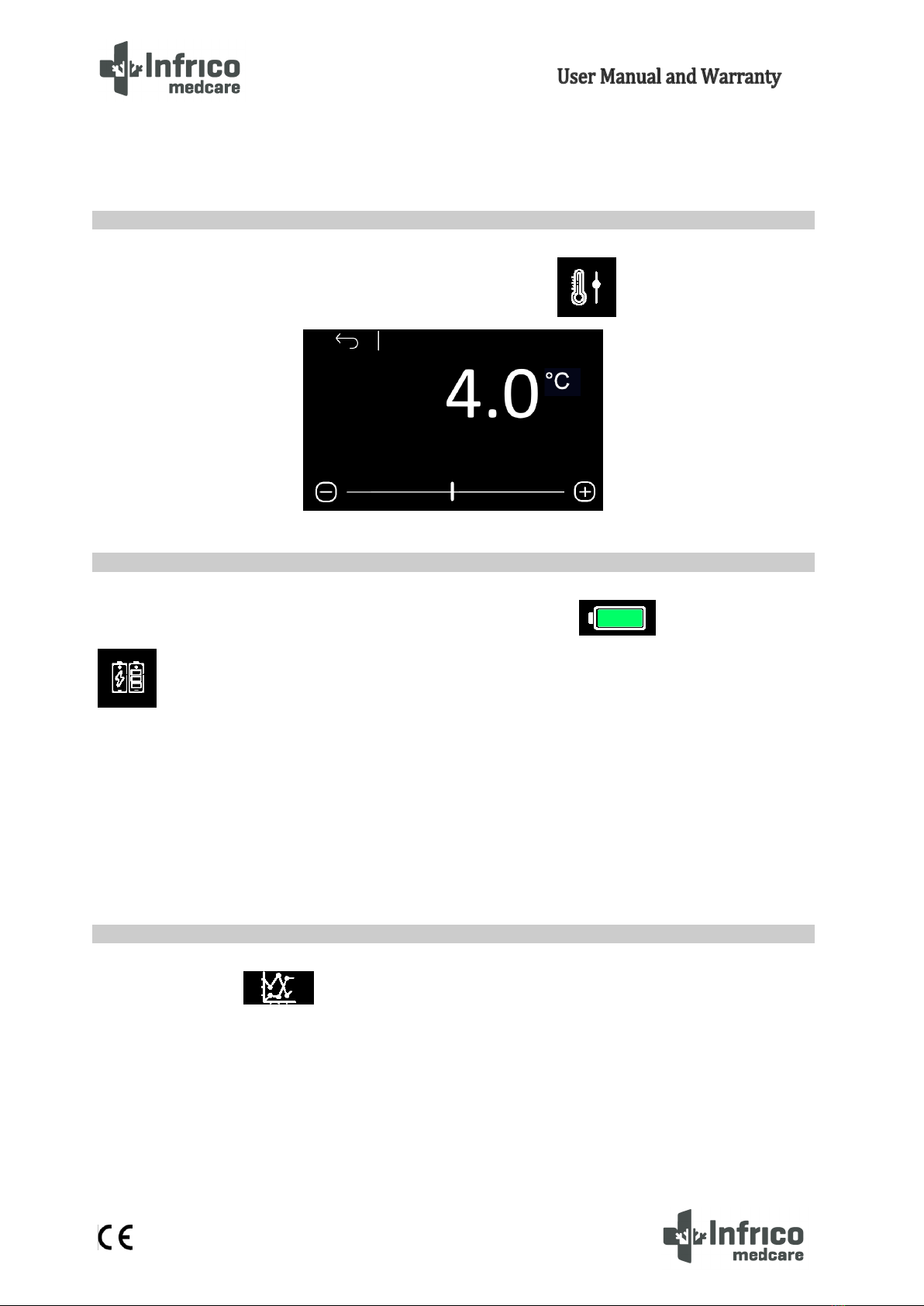
The temperature set point edit mode is enabled by pressing the icon on the home screen.
To know the battery status is possible to access with the following icon in the home screen or
through the main menu.
-In case of correct operation, the voltage provided by the battery will be displayed.
-In case of absence of the battery or any anomaly, the message "Battery problem" will be displayed.
If there are communication problems with the battery charger/back-up module, the message
"Information not present" will be displayed.
The "Battery Status" option can be enabled according to parameters or if the user logged in at that time
is enabled to display the battery status.
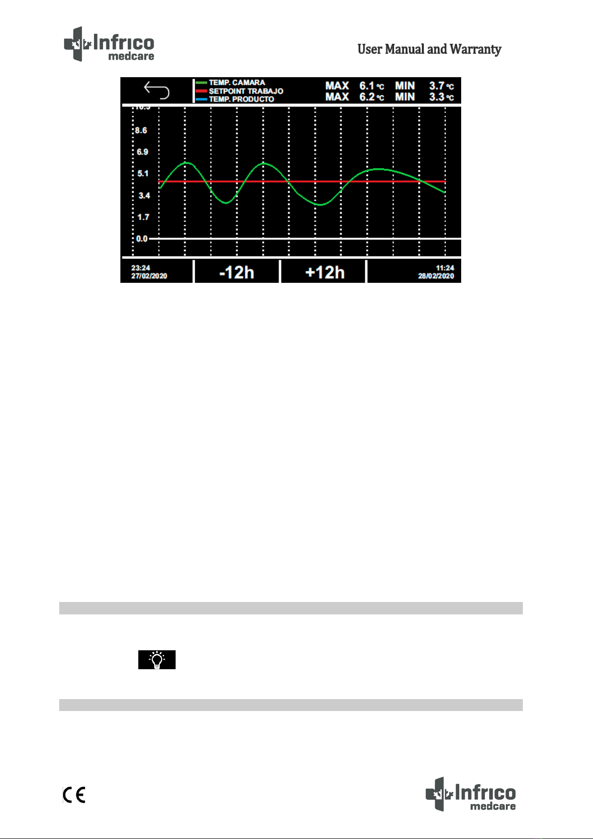
Press the icon to display the temperature chart with cabin and/or product temperature.
6.5 Set Point setting
6.6 Battery Status
6.7 Temperature chart
17
MAN-U-CLF86-EN Revisi0n: 03 16/02/2023
The screen shows in real time the last 12 hours.
The lines shown are the following:
- Product temperature in blue. (For ULF/ULT -86 will not be shown)
- Cabin temperature in green.
- Set point in red.
The coordinate axis (x) indicates the hours, while at the bottom left will indicate the time and date of
the first record shown, while at the bottom right the time of the last data that appears in the graph. The
ordinate axis (y) will show the minimum and maximum value of the temperatures.
Pressing the navigation icons, it will be possible:
-12h: It moves from the time -12 to the time -24 (with respect to the time 0 the request). And so on. If
the data is not present, the message “NO DATA” will appear indicating the absence of data registered with that
age.
+ 12h: Return with the graphics at time 0.
This function can be accessed manually, even if the keyboard is locked. The light switches on after
pressing the 'light' icon and after opening/closing the door.
To disconnect the audible alarm, proceed as follows:
1.- Make sure that no process is in progress.
6.8 Switching interior light on/off
6.9 Mute alarm

18
MAN-U-CLF86-EN Revisi0n: 03 16/02/2023
2.- Press icon.
When pressing the key, the following icon will be displayed.
To download the recorder data from the device, insert the USB key into the USB port on the keyboard
while visualizing the main screen. Then, the message “Historical data download” will be displayed and
confirming through “OK”, it will set the date / time for select the range of download (it will be between the date
selected and the current date).
Then, the option “Download historical data” will appear and when confirming this option through “OK”. You
must set the date / time from which, until the time of download we want to download the data. To set the date,
press on each value that you want to modify and press again on the value to confirm the change. After setting
the date, press “OK”.
The created file will have a .csv extension and can be opened by any spreadsheet application or Windows
notebook. Wait for the message to remove the key to be displayed when the operation to remove the USB key
has been completed.
Note: For the correct operation of the download, the USB key must be formatted in FAT32 and a USB 2.0 type. It
is recommended that the size of the pendrive as much of 16 GB.
PROHIBITION! The USB connector shall be used only to connect a pen-drive for programming and
data collection tasks.
6.10 Historical Data Download
This manual suits for next models
1
Table of contents


