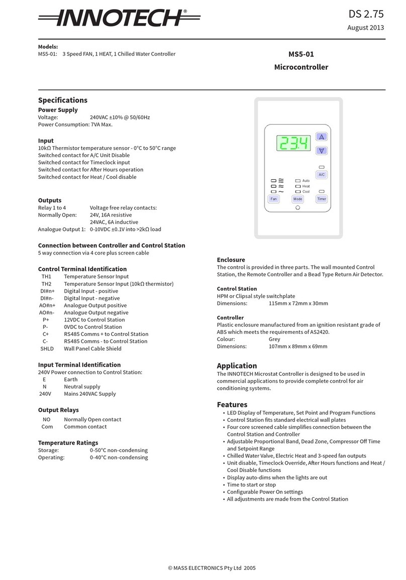
Innotech MS5-04 User manual

© MASS ELECTRONICS Pty Ltd 2005
Models:
MS5-04: 3 Speed FAN, 1 COOL, 1 HEAT, 1 Hot Water Controller
Specifications
Power Supply
Voltage: 240VAC ±10% @ 50/60Hz
Power Consumption: 7VA Max
Input
10kΩ Thermistor temperature sensor
Switched contact for AC Unit Disable
Switched contact for Timeclock input
Switched contact for Aer Hours operation
Switched contact for Heat / Cool disable
Outputs
Relay 1 to 4 Voltage free relay contacts:
Normally Open: 24V, 16A resistive
24VAC, 6A inductive
Analogue Output 1: 0-10VDC ±0.1V into >2kΩ load
Connection between Controller and Control Station
5 way connection via 4 core plus screen cable
Control Terminal Identification
TH1 Temperature Sensor Input (10kΩ thermistor)
TH2 Temperature Sensor Input (10kΩ thermistor)
DI#n+ Digital Input - positive
DI#n- Digital Input - negative
AO#n+ Analogue Output positive
AO#n- Analogue Output negative
P+ 12VDC to Control Station
P- 0VDC to Control Station
C+ RS485 Comms + to Control Station
C- RS485 Comms - to Control Station
SHLD Wall Panel Cable Shield
Input Terminal Identification
240V Power connection to Control Station:
E Earth
N Neutral supply
240V Mains 240VAC Supply
Output Relays
NO Normally Open contact
Com Common contact
Enclosure:
The control is provided in three parts. The wall mounted Control
Station, the Remote Controller and a Bead Type Return Air Detector.
Control Station
HPM or Clipsal style switchplate
Dimensions: 115mm x 72mm x 30mm
Controller
Plastic enclosure manufactured from an ignition resistant grade of
ABS which meets the requirements of AS2420.
Colour: Grey
Dimensions: 107mm x 89mm x 69mm
Temperature Ratings
Storage: 0-50°C non-condensing
Operating: 0-40°C non-condensing
DS 2.77
August 2013
MS5-04
Microcontroller
Application
The INNOTECH Microstat Controller is designed to be used in
commercial applications to provide complete control for air
conditioning systems.
Features
• LED Display of Temperature, Set Point and Program Functions
• Control Station fits standard electrical wall plates
• Four core screened cable simplifies connection between the
Control Station and Controller
• Adjustable Proportional Band, Dead Zone, Compressor O Time
and Setpoint Range
• Hot Water Valve (0-10V), Cool and 3-speed fan outputs
• Unit Disable, Timeclock Override, Aer Hours functions and
Heat/Cool Disable Functions
• Display auto-dims when the lights are out
• Time to start or stop
• Configurable Power On settings
• All adjustments are made from the Control Station
Fan TimerMode
Auto
Heat
Cool
A/C

© MASS ELECTRONICS Pty Ltd 2005
Page 2
DS 2.77 - MS5-04 - Microcontroller
August 2013
Installation
1. Mount in a dry and reasonable clean location free of excessive
vibration.
2. Wire in accordance with INNOTECH connection diagrams and
local bylaws or refer to your local distributor.
Wiring
1. Connect 240VAC supply to the correct terminals on the
controller, observing the correct polarity of the connections.
2. Connect the EARTH to the correct terminals on all units.
3. DO NOT connect 240VAC to the control terminals.
4. Ensure that the wiring between the control station and the
controller is correctly connected. Failure to do so will result in
malfunctioning and may damage either or both units.
5. The maximum wire length between the control station and
controller should not exceed 50 metres. The wiring between
these devices should not be run in parallel with conductors
carrying high current.
Digital Inputs
DI1 Timeclock
The Microcontroller is equipped with a remote timeclock enable
function.
When the time clock input (DI1) is "ON", the Microcontroller will run
in A/C mode.
DI2 Aer Hours
The Microcontroller is equipped with an Aer Hours timer.
When a pulse is received on the Aer Hours input (DI2), the unit will
run in A/C mode for the period set in Program Parameter 6.
If a pulse is received while the Microcontroller is in Aer Hours mode,
it will toggle o.
DI3 Unit Disable
The Microcontroller is equipped with an AC Unit Disable function.
If the Disable Input (DI3) is "ON" for the period set in Parameter 7, the
Microcontroller will shut down the air conditioning unit. When the
Microcontroller is disabled, the A/C LED will flash to indicate that it is
being overridden. When the remote disable input is opened, the unit
can be restarted by pressing the A/C button.
DI4 Device Disable
The Microcontroller is equipped with a Heat/Cool disable function.
If the remote disable input (DI4) is "ON" for the period set in
Parameter 9, the Microcontroller will shut down the specified A/C
devices (Heat only, Cool only or Heat and Cool) as indicated in
Parameter 8. If an A/C device is being overridden, the corresponding
Mode LED (Heat/Cool) will flash. When the input is turned o, the
unit will restart the A/C devices as required.
Analogue Outputs
AO1 Hot Water Valve
The Microcontroller is equipped with an output for a hot water valve.
When the Microcontroller is in heating mode, the analogue output
will vary linearly from 0-10V over the range of the Proportional Band
(Parameter 4).
Digital Display
The digital display will show the following error codes to assist with
fault finding.
• Display Reads "99.9"
This indicates either a faulty sensor or faulty sensor
cabling.
• Display Reads "HLP"
This indicates that communication between the Control
Station and Controller is not operating.
First check the interconnecting cabling and if this is OK, contact your
local Innotech Distributor for assistance.
Adjustable Parameters
Jumper Settings on the Control Station
Jumper #1 (JP1 Rev)
Not Used.
Jumper #2 (JP2 H/C)
Not Used.
Jumper #3 (JP3 Fan)
This jumper is used to select continuous fan operation or fan cycles
with heating.
When the link is closed, the fan runs continuously on cooling and
cycles with heating.
Program Functions on the Control Station
All variable settings for the Microcontroller are adjusted at the
Control Station.
Programming Mode
To enter Programming Mode, depress and hold the and
buttons for 5 seconds. The display will become blank indicating that
you are in the Programming Mode. Release both keys and the display
will show parameter 0.
While in the programming mode, the following buttons are active:
Change to the next parameter
Increase the current parameter value
Decrease the current parameter value
To Exit the Programming Mode, depress the and buttons
and the new setting will be saved.
This product should only be installed by qualified personnel.

© MASS ELECTRONICS Pty Ltd 2005
Page 3
DS 2.77 - MS5-04 - Microcontroller
August 2013
Parameter 0 - Sensor Calibration
The Display will show the sensor temperature. To oset the
sensor temperature, adjust using the or buttons.
• The range of the Oset is ± 9.9°C
• The factory default setting is 0.0°C
Parameter 1 - Minimum Setpoint
The display will show the Minimum Setpoint to which the
controller can be set.
• The range of the Minimum Setpoint is 0 to 99°C
• The factory default setting is 15°C
Parameter 2 - Maximum Setpoint
The display will show the Maximum Setpoint to which the
controller can be set.
• The range of the Maximum Setpoint is 0 to 99°C
• The factory default setting is 30°C
Parameter 3 - Dead Band
The display will show the Dead Band setting.
• The range of the Dead Band is 0 to 9.9°C
• The factory default is 1.0°C
Parameter 4 - Proportional Band
The display will show the Proportional Band (PB) setting. A PB
setting of 2°C will result in a dierential of 2°C for heating and 2°C
for cooling.
• The range of the Proportional Band is 0 to 9.9°C
• The factory default is 1.0°C
Parameter 5 - Fan Run On Time
The display will show the Fan Run On Time.
This is the period that fan will run for if it is operating in heating
mode and the controller is turned o. This is to remove any
residual heat where electric heating is used.
• The range of the Run On Time is 0 to 99 seconds.
• The factory default setting is 30 seconds.
Parameter 6 - Aer Hours Timer
The display will show the Aer Hours Time.
This is the period the unit will run for if an Aer Hours pulse is
received.
• The range of the Aer Hours Time is 0 to 9.9 hours.
• The factory default setting is 1 hour.
Parameter 7 - Unit Disable Timer
The display will show the Unit Disable Time.
This is the time that the controller must see the Unit Disable
input for before it turns o.
• The range of the Disable Timer is 0 to 99 minutes.
• The factory default setting is 1 minute.
Parameter 8 - Devices Disable
The display will show 4 settings of device disable.
• 0 - None, 1 - Heat, 2 - Cool, 3 - Heat and Cool
• The factory default setting is 3 - Heat and Cool.
Parameter 9 - Device Disable Timer
The display will show the Device Disable Time. This is the time that the
controller must see the device disable input for before it turns o the
specified devices.
• The range of the Device Disable Timer is 0 to 99 seconds.
• The factory default setting is 0 seconds.
Timer Function
The button when pressed will display the time in which the unit
will change state. For example: if the unit is o, the unit will display the
time till the unit will turn on. If the unit is on, it will display the time till it
will turn o.
Continuously pressing the button will increase this time by 10 minutes
until it reaches 24 hours, when it will then roll over and display the
minimum time adjustment. The time is adjustable from 10 minutes to
24 hours. If le for 5 seconds, the display will revert to displaying the
sensed temperature.
Mode Function
The button will switch between Auto, Heat and Cool modes.
In Auto mode, the unit will heat and cool as required to maintain the
setpoint conditions.
In heat mode, the cooling is disabled and the unit can only heat to
maintain set point conditions (winter mode).
In cool mode, the heating is disabled and the unit can only cool to
maintain conditions (summer mode).
Start Up Default Settings
The Microcontroller can be set to start in any mode of operation.
To set the start up default, adjust the Microcontroller to the desired
settings and then press and hold the and buttons for 5
seconds.
The display will become blank indicating that the new settings are
saved.
Factory Set Default Settings
Setpoint 22.5°C (0.0 to 99.9°C)
Operating Mode O (O / On)
Fan Speed High (Low / Medium / High)
A/C Cycle Auto (Auto, Heat, Cool)

© MASS ELECTRONICS Pty Ltd 2005
Page 4
DS 2.77 - MS5-04 - Microcontroller
August 2013
STANDARD CONNECTION
240VAC Supply
Neutral
Earth
TIMECLOCK
AFTER HOURS
UNIT DISABLE
DEVICE DISABLE
Screen MUST be
connected at both
the Control Station
and the Controller
P+
P-
C+
C-
SHLD
SENSOR
(Voltage Free Contacts by other)
TYPICAL DIGITAL INPUTS
To HW
Valve
(Voltage Free Contacts by other)
ALTERNATIVE DIGITAL INPUTS
+24V
0V
DI#+
DI#-
NOTE:
ALL DIGITAL INPUTS:-
Rated at:
24V (AC or DC)
Com
0-10V DC
DI
4
DI
1
DI
2
DI
3
Power Power
Fan Lo
Cool
Fan Med
Fan Hi
0V
NOTE:
ALL OUTPUT RELAYS:-
Rated at:
24V 16Amp Resistive
24VAC 6Amp Inductive
Com = Common Contact
NO = Normally Open Contact
ANALOGUE OUTPUT:-
Rated at:
0-10VDC into >2k Load
Ω
24V
* MAXIMUM CABLE LENGTH BETWEEN THE CONTROL STATION & CONTROLLER IS 50 METRES.
YOUR DISTRIBUTOR
Australian Owned, Designed & Manufactured
by Mass Electronics Brisbane
Phone: +61 7 3421 9100 Fax: +61 7 3421 9101
Email:
[email protected] www.innotech.com.au
The INNOTECH device and the word INNOTECH are registered or unregistered trademarks of Mass Electronics Pty Ltd in Australia, USA and other countries
Other Innotech Microcontroller manuals
Popular Microcontroller manuals by other brands
ST
ST STM32U575I-EV user manual
GigaDevice Semiconductor
GigaDevice Semiconductor GD32F20 Series user manual
Texas Instruments
Texas Instruments RM46 user guide
Altera
Altera Stratix IV GX Reference manual
PLX Technology
PLX Technology PCI 9056RDK-LITE Hardware reference manual
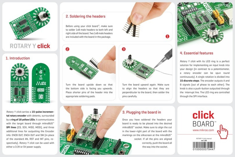
mikroElektronika
mikroElektronika ROTARY Y click quick start guide
