manuals.online logo
Brands
  1. Home
  2. •
  3. Brands
  4. •
  5. Innovation First
  6. •
  7. Robotics
  8. •
  9. Innovation First Victor 883 User manual

Innovation First Victor 883 User manual

Innovation First Victor883
January 2001 www.innovationfirst.com Users Manual -Page 1
The Victor 883 is a speed controller specifically
engineered for robotic applications. The high current
capacity, low voltage drop, and peak surge capacity make
the Victor 883 ideal for drive systems while its braking
options and precise control meet the demanding needs of
arms and lift systems. This controller safely handles the
high continuous current draws and extreme current surges
produced by FIRST Competition robots. Innovative FET
switching architecture and an integral cooling fan ensures
cool FET junction temperatures. The low voltage drop
and high switching speed ensures the motor receives
maximum power, providing significant improvements in
acceleration, direction changes, and lifting torque.
C
B
M
M
VICTOR883VICTOR883
Innovation First
W
B
R
LED Indicator
Brake/Coast Jumper
Cal Button
12V
GND
RED
BLK
TO BATTERY GND
and 12V BATTERY
RED
BLK
TO MOTOR
TO 30A BREAKER
Fan GND (BLK)
Fan 12V (RED)
PWM EXTENSION CABLE
TO RECEIVER PWM OUT
Wiring Guidelines
You will need (4) #6 or #8 circle lugs (yellow) for
10AWG wire and (2) #6 or #8 circle lugs (red) for
20AWG wire.
1. The fan must be wired so it is always ON when the
Victor 883 is ON.
2. Attach (2) 20AWG circle lugs to the fan wires and
connect to the Victor 883 input terminals 12V and
GND.
3. The input and output wires should be 10AWG wire
and firmly connected to ensure low voltage drop and
minimal temperature rise.
4. Use circle lugs designed for 10AWG wire. The lug
should have a hole designed for a #6 or #8 screw. If
the center hole is too large, (#10 or larger)
inadequate mechanical contact may result in
excessively high resistance and temperature rise.
5. Check all lug connection after crimping. You should
not be able to pull the lug off the wire with your
hands.
6. Once the input and output wires are firmly
connected, tie the wires using tie straps within 2” of
the Victor 883. This will ensure the wires do not
move and loosen the connections.
WARNING: BEFORE APPLYING POWER:
1. Ensure the input connections are not reversed.
Connecting 12V and GND backwards will
destroy the unit.
2. Ensure that there is not a short circuit on the
output. A short circuit will destroy the unit.
3. Ensure there is a 30A circuit breaker inline with
the 12v power input to the speed controller. This
ensures that long term exposure to a stalled
motor will not overheat the Victor 883.
LED Indicator Status
•Green = Full Forward
•Orange = Neutral / Brake
•Red = Full Reverse
•Flashing Orange = no PWM
Innovation First FIRSTVictor883
January 2001 www.innovationfirst.com Users Manual –Page 2
PWM Connection
You will need (1) PWM extension cable.
1. The male connector with the shroud connects to the
Victor 883. Remove shroud if necessary.
2. The PWM extension cable should be installed with
the black wire towards the fan.
3. Standard Radio Controlled PWM connectors are
fragile. Use caution when inserting and removing the
PWM cable so the contacts on both connectors are
not damaged.
Mounting Guidelines
You will need (2) #4 or #6 screws.
1. The Victor 883 can be installed in any orientation.
2. The Victor 883 must have adequate space above the
fan for airflow. Recommended clearance above the
Victor 883 is 2 inches.
3. Do not over-tighten the mounting screws through the
Victor 883. A snug connection will hold the Victor
883 in place without crushing the case.
Calibration Instructions
The Victor 883 is pre-calibrated to values compatible
with the FIRST control system. No calibration is
required for normal operation.
NOTE: While in calibration mode, the Victor 883 will
record the maximum PWM value detected as ‘full
forward’, the minimum PWM value as ‘full reverse’, and
‘neutral’ will be the PWM value recorded at the release
of the Cal button. The following steps will guide you
through this process.
User Calibration:
1. Power ON the speed controller.
2. Press and hold the Cal button. After a moment, the
indicator will begin alternating between RED and
GREEN to indicate calibration mode.
3. While continuing to hold the Cal button, move the
joystick to the maximum and minimum positions.
This can be done in any order and as many times as
desired.
4. While continuing to hold the Cal button, return the
joystick to center (neutral position).
5. Release the Cal button.
6. A flashing GREEN indicator confirms a successful
calibration.
7. A flashing RED indicator denotes an unsuccessful
calibration.
An unsuccessful calibration occurs when either:
a) Insufficient joystick travel was detected in forward
and/or reverse.
b) The trim tab is too far from center.
Resetting Calibration to FIRST Pre-calibration:
1. Power OFF the speed controller.
2. Press and hold the Cal button.
3. While continuing to hold the Cal button, Power ON
the speed controller.
4. A flashing GREEN indicator denotes calibration is
reset. Release the Cal button.
Brake / Coast Configuration
The Brake / Coast jumper is used to set the Victor 883’s
action during a neutral condition. The Brake provides
significant resistance to motor rotation and is
recommended for motors driving linkages and arms that
can be back-driven by gravity or other external forces.
The Victor 883 checks the status of the jumper
approximately 60 times per second. This allows the user
to change from brake to coast during operation. A limit
switch may be connected to the jumper connector instead
of the jumper. The limit switch can be triggered by
various means including the use of a servo. Refer to the
Application Note section on the Innovation First web site
for detailed instructions.
Brake / Coast Guidelines:
1. The jumper should always be installed in either the
Coast or Brake position. If you lose the jumper, a
standard computer jumper will work.
2. If no jumper is installed, the Victor 883 will default
to a Brake condition.
3. The Coast condition sets the output to an open
circuit during neutral.
4. The Brake condition sets the output to a short circuit
during neutral.
Innovation First FIRSTVictor883
January 2001 www.innovationfirst.com Users Manual –Page 3
Troubleshooting
Indication: No ORANGE indicator on power up.
Problem: Input power issue or joystick trim tab off
center.
Possible Solutions:
1. Disconnect PWM cable.
2. If indicator blinks ORANGE, the PWM value that
was being received is either between ‘neutral’ and
‘full forward’, or between ‘neutral’ and ‘full
reverse’. Check joystick trim tab to ensure the
controller is not in a partial forward or a partial
reverse condition. If no change, check that the
joystick and receiver channels match.
3. If indicator remains off, check 12V or GND
connections for voltage and proper polarity.
Indication: Flashing ORANGE indicator on power up.
Problem: No PWM signal.
Possible Solutions:
1. Ensure the FIRST receiver is powered ON.
2. The PWM cable may be improperly connected.
Check wire color-coding at each end. Check that the
connector is not off a pin at the Receiver end.
3. Check for a good PWM signal by connecting a
known good servo to the PWM extension cable. If
the servo does not move, this can indicate either:
a) a blown fuse in the FIRST receiver
b) an improperly connected cable
c) a bad PWM extension cable
Note: The servo requires that 5V be present on the
center pin of the PWM cable. This connection is not
required for the Victor 883. Fuse F18 supplies this 5V.
Indication: Flashing RED indicator after calibration.
Problem: Calibration Failed.
Possible Solutions:
1. Inadequate travel in forward or reverse. Repeat the
calibration procedure and move the joystick further
forward and/or further reverse.
2. The joystick trim tab is NOT centered. Neutral
cannot be extremely far from center.
Indication: No power output from the speed controller
although the indicator works.
Problem: Possible internal damage.
Possible Solutions:
If the indicator on the Victor 883 is operating properly
and there is no output, the Victor 883 may be internally
damaged. This condition is typically caused by a short
circuit on the output.
Check the following:
1. Ensure the indicator is changing between ORANGE,
RED and GREEN with joystick movement.
2. Disconnect the motor and check the output (M+ to
M-) with a voltmeter. The meter should read
between –12V and +12V.
If the indicator is working properly and the outputs are
not working properly, the speed controller is probably
damaged. The final test to determine if the Victor 883 is
damaged is to replace it with another Victor 883.
Indication: No power output from the speed controller
and the indicator does NOT work.
Problem: Possible internal damage.
Possible Solutions:
If the indicator on the Victor 883 is not operating
properly and there is no output, the Victor 883 may be
internally damaged. This condition is typically caused by
reverse polarity on the input.
Check the following:
1. Disconnect the output wires.
2. Ensure the indicator on the Victor 883 will not
illuminate at any joystick position.
3. Check the input at the Victor 883 (+12V to GND)
with a voltmeter.
If the indicator is not working properly and the input is
good, the speed controller is probably damaged. The
final test to determine if the Victor 883 is damaged is to
replace it with another Victor 883.
CAUTION: Prior to replacing a potentially damaged
speed controller, ensure that the wires connected to
the output are not shorted and the input is not
reversed. Also verify that neither of the motor output
leads are shorted to the chassis of the motor and/or
the robot.

Other Innovation First Robotics manuals

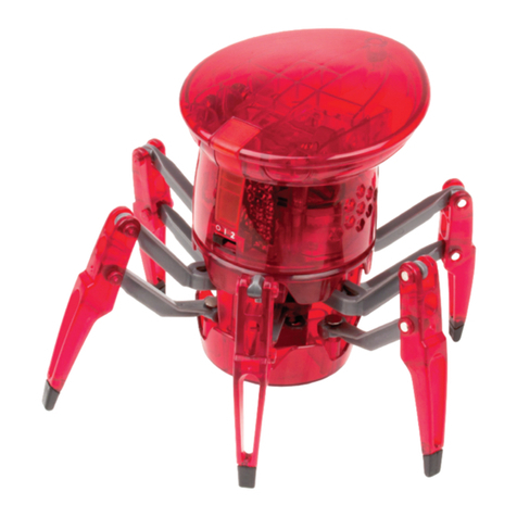
Innovation First HEXBUG spider XL User manual

Innovation First

Innovation First HEXBUG spider XL User manual

Innovation First HEXBUG BATTLE GROUND BUNKER 409-5121 User manual

Innovation First

Innovation First HEXBUG BATTLE GROUND BUNKER 409-5121 User manual

Innovation First HEXBUG BATTLEBOTS WITCH DOCTOR 413-5186 User manual

Innovation First

Innovation First HEXBUG BATTLEBOTS WITCH DOCTOR 413-5186 User manual

Innovation First HEXBUG VEX ROBOTICS MOBILE LAB 406-6106 User manual

Innovation First

Innovation First HEXBUG VEX ROBOTICS MOBILE LAB 406-6106 User manual

Innovation First HEXBUG VEX ROBOTICS SWITCHGRIP 406-5517 User manual

Innovation First

Innovation First HEXBUG VEX ROBOTICS SWITCHGRIP 406-5517 User manual

Innovation First HEXBUG VEX ROBOTICS GATLING RAPID FIRE... User manual

Innovation First

Innovation First HEXBUG VEX ROBOTICS GATLING RAPID FIRE... User manual

Innovation First HEXBUG VEX ROBOTICS CROSSBOW 406-6533 User manual

Innovation First

Innovation First HEXBUG VEX ROBOTICS CROSSBOW 406-6533 User manual

Innovation First HEXBUG VEX ROBOTICS PINCH BASE 228-8888 User manual

Innovation First

Innovation First HEXBUG VEX ROBOTICS PINCH BASE 228-8888 User manual

Innovation First HEXBUG VEX ROBOTICS TREBUCHET 406-6107 User manual

Innovation First

Innovation First HEXBUG VEX ROBOTICS TREBUCHET 406-6107 User manual

Popular Robotics manuals by other brands

Robokits TrackBot RKI-1247 Assembly guide and user manual

Robokits

Robokits TrackBot RKI-1247 Assembly guide and user manual

neobotix MMO-700 manual

neobotix

neobotix MMO-700 manual

Kondo KXR-L4D Assembly manual

Kondo

Kondo KXR-L4D Assembly manual

SunFounder PiDog manual

SunFounder

SunFounder PiDog manual

Feng Yuan Interstellar Warrior user guide

Feng Yuan

Feng Yuan Interstellar Warrior user guide

Epson ES Series MANIPULATOR MANUAL

Epson

Epson ES Series MANIPULATOR MANUAL

Wifibot Lab quick start guide

Wifibot

Wifibot Lab quick start guide

SCHUNK AGE-Z Series Assembly and operating manual

SCHUNK

SCHUNK AGE-Z Series Assembly and operating manual

Dobot CR5 user guide

Dobot

Dobot CR5 user guide

JAKA Zu pro Series Hardware user manual

JAKA

JAKA Zu pro Series Hardware user manual

Sphero Misty II quick start guide

Sphero

Sphero Misty II quick start guide

WLKATA Mirobot user manual

WLKATA

WLKATA Mirobot user manual

CAMDUSTER V2203 installation manual

CAMDUSTER

CAMDUSTER V2203 installation manual

ABB IRB 14000 product manual

ABB

ABB IRB 14000 product manual

Jsumo M1 manual

Jsumo

Jsumo M1 manual

LSLIDAR M10P user manual

LSLIDAR

LSLIDAR M10P user manual

Omron TM Robot TM12 Series Hardware installation manual

Omron

Omron TM Robot TM12 Series Hardware installation manual

AgileX SCOUT MINI user manual

AgileX

AgileX SCOUT MINI user manual

manuals.online logo
manuals.online logoBrands
  • About & Mission
  • Contact us
  • Privacy Policy
  • Terms and Conditions

Copyright 2025 Manuals.Online. All Rights Reserved.