INOXPA MH Manual
HORIZONTAL BLENDER
MH
Original Instructions
02.001.30.01EN
(0) 2022/02
INSTALLATION, SERVICE AND MAINTENANCE INSTRUCTIONS
02.001.32.0001

E C D e c l a r a t i o n o f C o n f o r m i t y
Model:
INOXPA S.A.U.
Telers, 60
17820 - Banyoles (Spain)
hereby declare under our sole responsibility that the
MH
Technical Oce Manager
20th January 2021
02.001.30.02EN
(0) 2022/01
Document:
Revision:
Machine: HORIZONTAL BLENDER
David Reyero Brunet
Serial number: IXXXXXXXXX to IXXXXXXXXX
fullls all the relevant provisions of the following directive:
Machinery Directive 2006/42/EC
Regulation (EC) nº 1935/2004
Regulation (EC) nº 2023/2006
and with the following harmonized standards and/or regulations:
EN ISO 12100:2010
EN 809:1998+A1:2009/AC:2010
EN 60204-1:2018
The technical le has been prepared by the signer of this document.
XXXXXXXXXIINXXX to XXXXXXXXXIINXXX
Type: MH-20, MH-26

D e c l a r a t i o n o f C o n f o r m i t y
Model:
INOXPA S.A.U.
Telers, 60
17820 - Banyoles (Spain)
hereby declare under our sole responsibility that the
MH
02.001.30.03EN
(0) 2022/01
Document:
Revision:
Machine: HORIZONTAL BLENDER
Type: MH-20, MH-26
Technical Oce Manager
20th January 2021
David Reyero Brunet
fulls all the relevant provisions of these regulations:
Supply of Machinery (Safety) Regulations 2008
and with the following designated standards:
The technical le has been prepared by the signer of this document.
Serial number: IXXXXXXXXX to IXXXXXXXXX
XXXXXXXXXIINXXX to XXXXXXXXXIINXXX
EN ISO 12100:2010
EN 809:1998+A1:2009/AC:2010
EN 60204-1:2018

1. Table of Contents
1. Table of Contents
2. Generalities
2.1. Instructions manual.................................................................................................................................5
2.2. Compliance with the instructions ............................................................................................................5
2.3. Warranty..................................................................................................................................................5
3. Safety
3.1. Warning symbols.....................................................................................................................................6
3.2. General safety instructions .....................................................................................................................6
4. General Information
4.1. Description ..............................................................................................................................................8
4.2. Operating principle..................................................................................................................................8
4.3. Products to be avoided ...........................................................................................................................8
4.4.Application...............................................................................................................................................8
5. Installation
5.1. Reception of the blender.......................................................................................................................10
5.2. Identication of the blender...................................................................................................................10
5.3.Transport and storage........................................................................................................................... 11
5.4. Location ................................................................................................................................................ 11
5.5. Pipes .....................................................................................................................................................12
5.6. Electrical installation .............................................................................................................................12
6. Start-up
6.1. Checks before starting the blender .......................................................................................................13
6.2. Checks when starting the blender......................................................................................................... 13
7. Troubleshooting
8. Maintenance
8.1. General considerations .........................................................................................................................15
8.2. Check the mechanical seal ...................................................................................................................15
8.3. Maintenance of the seals ......................................................................................................................15
8.4.Tightening torque ..................................................................................................................................15
8.5. Storage .................................................................................................................................................15
8.6. Cleaning................................................................................................................................................16
8.7. Disassembly and assembly of the blender ...........................................................................................17
8.8. Disassembly of the MH-20 blender.......................................................................................................17
8.9. Disassembly of the MH-26 blender.......................................................................................................19
8.10. Disassembly of the HYGINOX SE pump ............................................................................................20
8.11.Montaje de la bomba HYGINOX SE ...................................................................................................21
8.12.Assembly of the MH-20 blender..........................................................................................................22
8.13.Assembly of the MH-26 blender..........................................................................................................23
9. Technical Specications
9.1. Weights and dimensions.......................................................................................................................25
9.2. Exploded drawing of MH-20 blender..................................................................................................... 26
9.3. Parts list of MH-20 blender ...................................................................................................................27
9.4. Exploded drawing of MH-26 blender..................................................................................................... 28
9.5. Parts list of MH-26 blender ...................................................................................................................28
9.6.Technical section of HYGINOX SE pump ............................................................................................. 29
9.7. Parts list of HYGINOX SE pump...........................................................................................................30
Table of Contents
INOXPA S.A.U. 02.001.30.01EN · (0) 2022/02
4

2. Generalities
2.1. INSTRUCTIONS MANUAL
This manual contains information about the reception, installation, operation, assembly and mainte-
nance of the MH blenders.
Carefully read the instruction before starting the blender, familiarize yourself with the installation,
operation and correct use of the blender and strictly follow the instructions. These instructions should
be kept in a safe location near the installation area.
The information published in the instruction manual is based on updated data.
INOXPA reserves the right to modify this instruction manual without prior notice.
2.2. COMPLIANCE WITH THE INSTRUCTIONS
Not following the instructions may impose a risk for the operators, the environment and the machine,
and may cause the loss of the right to claim damages.
This non-compliance may cause the following risks:
- failure of important machine/plant functions,
- failure of specic maintenance and repair procedures,
- possible electrical, mechanical and chemical hazards.
2.3. WARRANTY
The conditions of the warranty are specied in the General Sales Condition that has been delivered
at the time of placing your order.
The machine may not undergo any modication without prior approval from the manu-
facturer.
For your safety, only use original spare parts and accessories. The usage of other parts
will relieve the manufacturer of any liability.
Changing the service conditions can only be carried out with prior written authorization
from INOXPA.
Please do not hesitate to contact us in case of doubts or if further explanations are required regarding
specic data (adjustments, assembly, disassembly, etc.).
The non-compliance of the prescribed indications in this manual means misuse of this gear on
the technical side and the personal safety and this, exempt INOXPA of all responsibility in case
of accidents and personal injuries and/or property damage. Also, excluded from the warranty all
breakdowns caused by improper use of the gear.
Generalities
5
INOXPA S.A.U. 02.001.30.01EN · (0) 2022/02
3.1. WARNING SYMBOLS
3. Safety
Safety hazard for people in general and/or for the equipment
ATTENTION Important instruction to prevent damage to the equipment and/or its function
3.2. GENERAL SAFETY INSTRUCTIONS
Read the instruction manual carefully before installing and starting the blender. Contact
INOXPA in case of doubt.
3.2.1. During installation
Electric hazard
Always take into account the Technical Specications of chapter 9.
Never start the blender before connecting it to the lines.
Do not start up the blender if the cover has been removed and the impeller is xed to the
blender.
During the installation, all the electric work should be carried out by authorized personnel.
Check for proper specications of the motors, especially if working conditions create an
explosions hazard.
3.2.2. During operation
The Technical Specications of chapter 9 should always be observed.
Under no circumstances can the specied limit values be exceeded.
NEVER touch the blender or the pipework during operation if the blender is being used
for transferring hot liquids or during cleaning.
The blender contains moving parts. Never place your ngers inside the blender during
operation.
NEVER operate with the suction and discharge valves closed.
NEVER spray water directly on the electrical motor. The standard motor protection is
IP55: protection against dust and water spray.
The blenders and their installation may cause noise levels that exceed 85 db(A) in some
unfavourable operating environments. In such cases, operators should wear hearing
protection.
Safety
INOXPA S.A.U. 02.001.30.01EN · (0) 2022/02
6

3.2.3. During maintenance
The Technical Specications of chapter 9 shall always be observed.
NEVER disassemble the blender until the pipes have been emptied. Remember that
liquid will remain inside the housing (if does not have a purge). Bear in mind that the
product may be hazardous or extremely hot. Consult the regulations in eect in each
country for these cases.
Do not leave loose parts on the oor.
ALWAYS disconnect the electrical power to the blender prior to carrying out any mainte-
nance.
Remove the fuses and disconnect the cable from the motor’s terminals.
All electrical work must be carried out by authorized personnel.
Safety
7
INOXPA S.A.U. 02.001.30.01EN · (0) 2022/02

4. General Information
4.1. DESCRIPTION
4.2. OPERATING PRINCIPLE
The MH blender is a compact unit. It consists of a centrifugal pump with a venturi system and a ho-
pper above which there is a hopper with a buttery valve. The solids are added through the hopper
to the pumper liquid.
The pump is in the Hyginox SE range. This pump is a close-coupled centrifugal pump with a hygienic
and horizontal design and a single-stage. It is has a circular casing with axial suction and a tangential
discharge. The main pump components are pump casing, impeller, cover, lantern and a shaft that is
rigidly coupled to the motor shaft. The standard IEC motor of type is protected by a stainless steel
shroud.
The aspiration of the pump creates a suction that aspirated the solids of the hopper in a way that
the solids are incorporated into the liquid. Continuedly, the ow passes through the centrifugal pump
where the premix of the solid is created.
The inlet of solids is regulated by a buttery valve on the basis hopper. The tube in which the inlet of
the pump is produced remains dry during the blender operation. If the inlet tube is plugged, check
that the pump direction of rotation is correct and check the ow is sucient.
The reasons why the powder may become damp or wet are:
-incorrect liquid-intake ow rate: with a little ow, normally created by back pressure on the
discharge of the blender too high, is possible that the ow is not being able to drag the solids
which enter from the hopper and, even they rise through the tube to the hopper.
-incorrect pressure: the dierential pressure of the blender must be low (6-9 m), and the pres-
sure at the blender intake must be negative but without causing cavitation because it is counter-
productive.
-high viscosity: due to its nature, a viscous product will cause counterpressure. This can cause
the blender to move an inadequate ow to its correct functioning. A centrifugal pump dramatically
reduces its ow if the product viscosity increase.
-high discharge pressure: if the discharge pipe is too long or its diameter is too small a very
high counterpressure will be caused.
To avoid these problems the piping must be of correct dimensions. It is important to maintain nega-
tive pressure at the blender intake.
The amount of powder that can be added is very dicult to dene, as a great number of variables
are involved like dampness, fatty material content, microscopic texture (smooth, rough), density,
uidity, powder type (granular, aky, ne), etc.
The MH blenders are suitable for his use in food processing. They can be used in any process which
needs to mix solids and liquids suchs as powdered milk, whey, chocolates, sauces, brines, fertilisers,
lactose, stabilisers, etc.
4.3. PRODUCTS TO BE AVOIDED
4.4. APPLICATION
The products to be avoided in order to have a blender optimum operation are:
-abrasives: these products deteriorate the mechanical seals and impellers.
-eervescent: the gas that emits these products prevents the vacuum from forming and the
powder from falling from the hopper.
-high temperatures: it is not advised to work at temperatures above 65⁰C. Also, if the tempera-
ture approaches the boiling point can cause cavitation in the blender.
-very high viscosities: the blenders cannot pump products with a viscosity above 250 cPs.
-incompatible products: products incompatible with the various mechanical seals and
elastomers.
General Information
INOXPA S.A.U. 02.001.30.01EN · (0) 2022/02
8

ATTENTION
The range of application for each type of blender is limited. The blender was selected for
a given set of conditions when the order was placed. Misuse or its use beyond the ope-
rating limits may be dangerous or cause permanent damage to the equipment. INOXPA
shall not be liable for any damage resulting from the incompleteness of the information
provided by the purchaser (nature of the uid, rpm, etc.)
General Information
9
INOXPA S.A.U. 02.001.30.01EN · (0) 2022/02

5.1. RECEPTION OF THE BLENDER
5. Installation
The blender package includes the following documents:
- shipping documents,
- installation, service and maintenance instructions manual,
- instructions and service manual of the motor1
1) if the blender has been supplie with a motor from INOXPA
INOXPA cannot be held responsible for the damage sustained by the equipment during
transport or unpacking. Please visually check that the packaging is not damaged.
Unpack the blender and check the following:
- the suction and discharge connections of the blender and the blender hopper are not damaged
and remove any rest of the packaging material,
- the blender is not damaged,
If the equipment is not in good condition and/or any part is missing, the carrier should report
accordingly as soon as possible.
5.2. IDENTIFICATION OF THE BLENDER
Each blender has a nameplate with the basic data required to identify the model.
C. TELERS, 60 - 17820 BANYOLES
GIRONA (SPAIN) . www.inoxpa.com
INOXPA S.A.U.
Type
Year
No
R
Serial number
01.214.32.0014
02.001.32.0002
Installation
INOXPA S.A.U. 02.001.30.01EN · (0) 2022/02
10
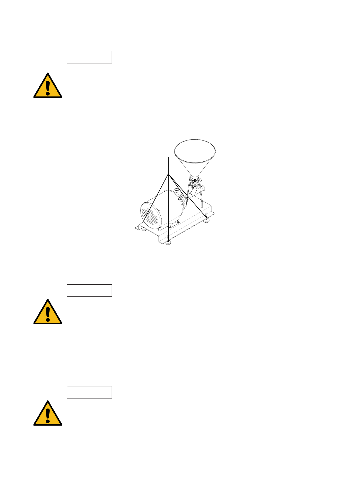
5.3. TRANSPORT AND STORAGE
The MH blenders are often too heavy to be stored manually.
Use an appropriate means of transport.
Use the points which are indicated in the drawing for lifting the blender.
Only authorized personnel should transport the blender.
Do not work or walk under the heavy loads.
Lift the blender as indicated below:
- always use two support points placed as far apart as possible.
ATTENTION
- secure the supports so that they will not move.
See chapter 9. Technical Specications to consult the dimensions and weight of the blender.
During the transport, disassembly or assembly of the blender, there is a risk of loss of
stability and that the blender could fall down and cause damages to the operators. Make
sure that the blender is properly supported.
5.4. LOCATION
Place the blender as close as possible to the suction tank whenever possible below the liquid and
leaving enough space around to can access the blender and the motor. If necessary, consult in chap-
ter 9. Technical Specications the dimensions of the blender.
Once a place is chosen, the blender should be mounted on a at and level surface.
Install the blender so as to allow proper ventilation.
If the blender is installed outdoors, it should be covered by a roof. Its location should
allow easy access for inspection or maintenance operations.
5.4.1. Excessive temperatures
Depending on the uid to be mixed, high temperatures can be reached inside and around the blender.
ATTENTION
ATTENTION
02.001.32.0003
Installation
11
INOXPA S.A.U. 02.001.30.01EN · (0) 2022/02
Over 68ºC the operator should take protective measures and place warning notices
advising of the danger which exists if the blender is touched.
The type of protection selected should not isolate the blender entirely.
5.5. PIPES
About the installation pipes:
- As a general rule, install the suction and discharge lines in straight sections, with the minimum
possible number of elbows and ttings to reduce any pressure losses that may be caused by
friction.
- Make sure that the blender’s ports are properly aligned with the pipework and have a diameter
similar to that of the blender connections.
- Place the blender as close as possible to the suction tank and whenever possible below the
liquid level in order to achieve its priming .
- Install support brackets for the lines as close as possible to the blender’s suction and discharge
ports.
5.5.1. Shut-o valves
The blender may be isolated for maintenance. To accomplish this, shut-o valves must be installed
and connected to the blender’s suction and discharge connections.
5.6. ELECTRICAL INSTALLATION
Only qualied personnel can connect the electric motors.
Take the necessary measures to prevent damage to cables and connections.
Electrical equipment, terminals and components of the control systems may still carry
current when they are disconnected. Contacting them may impose a hazard to operators
or cause irreparable material damage.
Before handling the blender make sure that the motor is stopped.
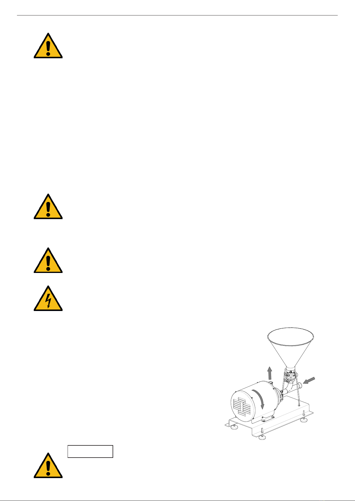
To do the electrical installation:
- connect the motor in accordance with the instructions
supplied by the motor manufacturer, in accordance with
the current national legislation and in compliance with EN
60204-1,
- check the direction of rotation (see the signalling label on
the blender),
- start and stop the blender motor momentarily. Make sure,
looking at the blender by the hopper side, that the rotation
direction of the motor fan is counterclockwise.
02.001.32.0004
ALWAYS check the direction of rotation of the motor with liquid inside the pump.
ATTENTION
These valves must ALWAYS be open during operation of the mixer.
Installation
INOXPA S.A.U. 02.001.30.01EN · (0) 2022/02
12

Before starting the blender:
- completely open the shut-o valves on the suction and discharge lines,
- if the liquid does not ow towards the blender, ll it with the liquid to be mixed,
6. Start-up
6.1. CHECKS BEFORE STARTING THE BLENDER
Before starting the blender, carefully read the instructions in section 5. Installation.
Carefully read section 9. Technical Specications. INOXPA will not be liable for improper
use of the equipment.
NEVER touch the blender or the lines of hot liquids that are being mixed.
The blender must never turn dry.
- check that the power supply matches the rating indicated on the motor plate.
- check that the motor rotation direction is correct.
- check that the impeller of the pump rotates without friction.
ATTENTION
6.2. CHECKS WHEN STARTING THE BLENDER
When starting the blender check:
- that the blender is not making any strange noises,
- check the ow pressure,
- that there are no leaks in the sealing areas.
Shut-o valves on the suction pipe must not be used to regulate the ow. All shut-o
valves must be fully open during operation.
ATTENTION
Control the motor consumption to prevent an electrical overload.
ATTENTION
Use special protection when the sound pressure in the operation area exceeds 85 dB(A).
Start-up
13
INOXPA S.A.U. 02.001.30.01EN · (0) 2022/02

7. Troubleshooting
The following table provides solutions to problems that might arise during the operation of the blender.
The blender is assumed to have been properly installed and be suitable for the relevant application.
Please contact INOXPA if technical assistance is required.
The blender does not suction
Insucient pressure on impulsion
Motor overload
Noise
Vibrations
Leaks
PROBABLE CAUSES SOLUTIONS
• Wrong motor rotation direction Reverse the motor rotation direction
• Very high powder percentage See chapter 4. General Information
• Very high temperature Reduce temperature
• • Leaks in the supply pump suction Check the suction pipe and all of its connections
• • Worn mechanical seal Replace the blender mechanical seal and/or su-
pply pump mechanical seal
•Dierential pressure is too high Reduce pressure. See chapter 4. General Infor-
mation
• The suction pressure is too high Reduce suction pressure. See chapter 4.
General Information
•Insucient liquid Check the supply pump
• Viscosity product or delivery height is too high Install a suction pump
• Pump working at the end of the curve Close partially the valve between the pump and
the mixer
• Worn motor bearings Replace bearings as indicated on the manufac-
turer instruction manual
• • Foreign bodies inside the blender
Disassemble the blender and remove the
foreign bodies. Verify the housing, the impeller
and the mechanical seal
• The blender is not at the right level Correct the level and the alignment of the
blender
• The impeller is damaged Replace the impeller
•Blender cavitation Reduce the pressure drop on the suction or use
a suction pump
•O-rings inadequate for the uid Mount the correct O-rings consulting previously
with the supplier
• Spring mechanical seal tension is too low Adjust according to the Instruction Manual
• Clamp is loose Tighten the clamp
• The blender suction little dust Check tha the zone of the valve and the bottom
of the hopper are not dry
Increase the ow of the hopper
• Fluid loss by the hopper Decrease the liquid heigh of the suction tank
In pressurized tanks, reduce the internal pres-
sure of the tank
• • • Presence of air in the pipe Check that the air is not entered by the hopper
avoiding having the valve opened when the
solids entering the venturi is nished
Troubleshooting
INOXPA S.A.U. 02.001.30.01EN · (0) 2022/02
14

8. Maintenance
8.1. GENERAL CONSIDERATIONS
8.2. CHECK THE MECHANICAL SEAL
8.3. MAINTENANCE OF THE SEALS
SEALS REPLACEMENT
Preventive maintenance Replace after twelve (12) months. We also recommend repla-
cing the gaskets during mechanical seal replacement.
Maintenance after a leak Replace at the end of the process
Scheduled maintenance
Regularly check that there are no leaks and that the blender
is operating correctly.
Keep a maintenance record of the blender.
Use statistics to plan inspections.
Lubrication
During assembly, use soapy water or oil compatible for the
food industry when tting the dierent gaskets to allow them
to slide better.
This blender, just like any other machine, requires maintenance. The instructions contained in
this manual cover the identication and replacement of spare parts. The instructions are aimed at
maintenance personnel and those responsible for the supply of spare parts.
Carefully read chapter 9. Technical Specications.
Maintenance work can only be carried out by qualied personnel that are trained and
equipped with the necessary resources to carry out this work.
All parts or materials that are replaced must be properly disposed of/recycled in
accordance with the current directives applicable in each area.
ALWAYS disconnect the blender before beginning any maintenance work.
Periodically check that there are no leaks around the shaft. If leakage is detected through the
mechanical seal, replace it following the instructions in chapter 8.10. Disassembly of the Hyginox SE
pump and 8.11. Assembly of the Hyginox SE pump.
The period between each preventive maintenance service will vary depending on the operating
condition of the blender: temperature, ow, number de cycles per day, cleaning solutions used, etc.
8.4. TIGHTENING TORQUE
Size Nm lbf·ft
M6 10 7
M8 21 16
M10 42 31
M12 74 55
M16 112 83
8.5. STORAGE
Before being stored the blender must be completely emptied of liquids. Avoid, as far as possible, the
exposure of the parts to excessively damp atmospheres.
Maintenance
15
INOXPA S.A.U. 02.001.30.01EN · (0) 2022/02
8.6. CLEANING
The use of aggressive cleaning products such as caustic soda and nitric acid may give
raise to skin burns.
Use rubber gloves during cleaning procedures.
Always use protective goggles.
8.6.1. Automatic CIP (clean-in-place)
If the blender is installed in a system with a CIP process, it is not necessary to disassemble the
blender.
If the automatic cleaning process is not provided, proceed to disassemble the blender as indicated
in the chapter 8.7. Disassembly and assembly of the blender.
ATTENTION
Check the concentration of the cleaning solutions. Incorrect concentrations may lead to
the deterioration of the blender seals.
To remove any traces of cleaning products ALWAYS perform a nal rinse with clean water at the end
of the cleaning process.
Two types of solutions can be used for CIP processes:
a. alkaline solution: 1% by weight of caustic soda NaOH a 70ºC (150ºF). To make this solution:
1 kg NaOH + 100 l H2O1= cleaning solution
2,2 l NaOH 33% + 100 l H2O = cleaning solution
b. acid solution: 0,5% by weight of nitric acid HNO3 a 70ºC (150ºF). To make this solution:
0,7 l HNO353% + 100 l H2O = cleaning solution
1) only use chlorine-free water to mix with the cleaning agents
8.6.2. Automatic SIP (sterilization-in-place)
The steam sterilisation process is applied to all equipment including the blender.
Do NOT operate the equipment during the steam sterilisation process.
The parts and the materials will not suer damage provided the instructions set out in
this manual are followed.
Cold liquid cannot be introduced until the blender temperature is below 60ºC (140ºF).
The blender generates a substantial pressure loss through the sterilisation process. We
recommend the use of a bypass circuit provided with a discharge valve to ensure that the
steam or overheated water sterilises the entire circuit.
Maximum conditions during the steam or overheated water SIP process:
a. maximum temperature: 140ºC / 284ºF
b. maximum time: 30 min
c. cooling: sterile air or inter gas
d. materials: EPDM (the materials HNBR y FPM are not recommended)
ATTENTION
Maintenance
INOXPA S.A.U. 02.001.30.01EN · (0) 2022/02
16
8.7. DISASSEMBLY AND ASSEMBLY OF THE BLENDER
The assembly and disassembly of the blenders should be done by qualied personnel. Make sure
that the personnel read carefully this instruction manual and, in particular, those instructions which
refer to the work they will perform.
ATTENTION
Incorrect assembly or disassembly may cause damage in the blender’s operation and
lead to high repair costs and a long period of downtime.
INOXPA is not responsible for accidents or damages cause by a failure to comply with
the instructions in this manual.
Preparation
Provide for a clean working environment so some parts, including the mechanical seal, require very
careful handling and others have close tolerances.
Check that the parts which are used are not damaged during transport. When doing this, you need
to inspect the adjustment edge, the butted faces, the tight t, burrs, etc.
After each disassembly, carefully clean the parts and check for any damage. Replace all damaged
parts.
Tools
Use the proper tools for assembly and disassembly operations. Use them correctly.
Cleaning
Before disassembling the blender, clean it outside and inside.
8.8. DISASSEMBLY OF THE MH-20 BLENDER
Before starting to perform the disassembly works of the blender:
- disconnect the motor of the suction pump
- close the suction and discharge valve of the pump
- place some trays for collection of liquids
Use gloves and safety goggles to empty the blender.
Maintenance
17
INOXPA S.A.U. 02.001.30.01EN · (0) 2022/02
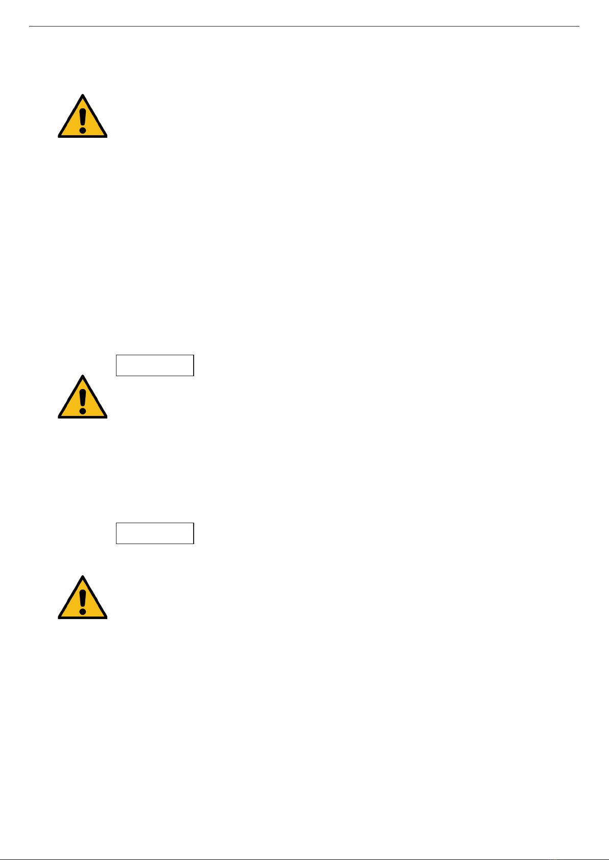
02.001.32.0005
1. Loosen and remove the screws and nuts of the su-
pport (29) of the hopper (101).
2. Remove the clamp (92) that joints the hopper (101)
to the buttery valve (96).
3. Remove the hopper (101).
8.8.1. Disassembly of the hopper
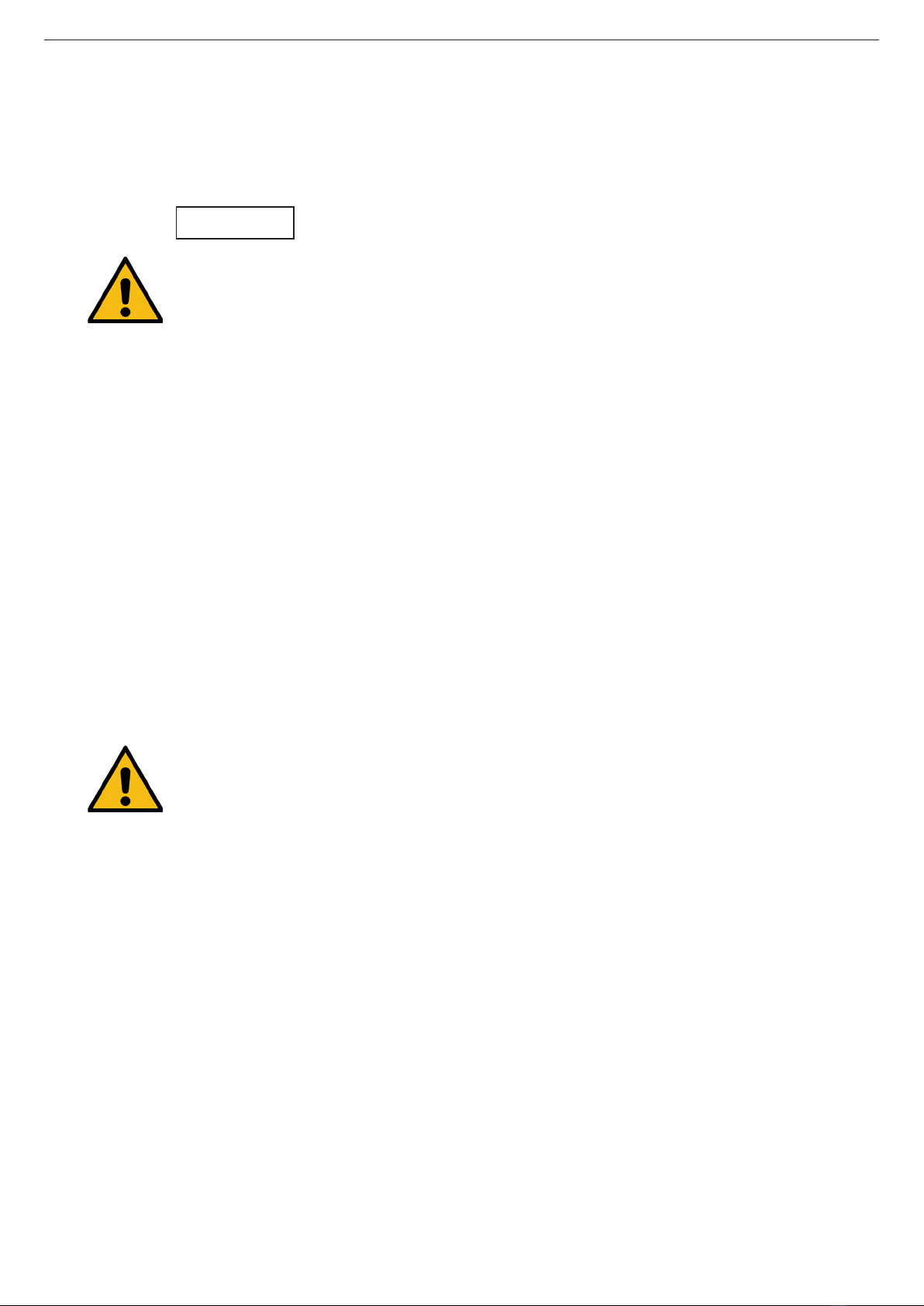
8.8.2. Disassembly of the venturi tube
1. Remove the clamp (92) that joins the pump to the
venturi tube (102).
2. Remove the clamp (92) that joins the venturi tube
(102) to the buttery valve (96).
3. Remove the venturi tube (102).
02.001.32.0006
When the disassembly of the hopper and the venturi tube is nished proceed to disassembly the
Hyginox SE pump following the instructions of chapter 8.10. Disassembly of the Hyginox SE pump.
29
92
102
92
96
Maintenance
INOXPA S.A.U. 02.001.30.01EN · (0) 2022/02
18

8.9. DISASSEMBLY OF THE MH-26 BLENDER
Before starting to perform the disassembly works of the blender:
- disconnect the motor of the suction pump
- close the suction and discharge valve of the pump
- place some trays for collection of liquids
Use gloves and safety goggles to empty the blender.
8.9.1. Disassembly of the hopper
1. Loosen and remove the blind nuts (54B).
2. Loosen the nuts (54A) and remove the threaded
rods (55).
3. Remove the clamp (92) that joins the hopper (101)
to the buttery valve (96).
4. Remove the hopper (101).
54A
92,92A
101
54B
54A
02.001.32.0009
8.9.2. Disassembly of the venturi tube
1. Remove the clamp (92B) of the venturi tube
support of the base plate (38).
2. Remove the clamp (92) that joins the pump to the
venturi tube (102).
3. Remove the clamp (92) that joins the venturi tube
(102) to the buttery valve (96).
4. Remove the venturi tube (102).
02.001.32.0010
Maintenance
19
INOXPA S.A.U. 02.001.30.01EN · (0) 2022/02

1. Remove the clamping ring (15) and disassemble
the pump casing (01).
2. Check the condition of the O-ring (80A) on the
pump casing and replace it if damaged.
02.001.32.0013
3. Place an open-end wrench on the at sides of the
shaft (05) to prevent it from rotating.
4. Remove the impeller nut (45) and the O-ring (80A).
5. Pull out the impeller (02). If necessary, hit it with
a dead blow using a plastic mallet in order to
disengage the cone.
6. Remove the rotating part of the seal (08) from the
rear side of the impeller (02).
7. Remove the pump cover (03) from the lantern (04).
8. Manually remove the stationary part of the seal
(08) which is located in the pump cover (03)..
02.001.32.0014
9. Remove the splash ring (82) from the shaft (05).
10. Loosen the studs (55) from the shaft (05) and
take them o from the motor (93).
02.001.32.0015
8.10. DISASSEMBLY OF THE HYGINOX SE PUMP
92,92A
102
92,92A
96
When the disassembly of the hopper and the venturi tube is nished proceed to disassembly the
Hyginox SE pump following the instructions of chapter 8.10. Disassembly of the Hyginox SE pump.
02.001.32.0011
Maintenance
INOXPA S.A.U. 02.001.30.01EN · (0) 2022/02
20
Table of contents
Other INOXPA Blender manuals


