Insolroll Oasis 2700 User manual

Page 1 of 11
For more assistance: Insolroll, Inc. www.Insolroll.com 800- 447-5534 Version 02
Oasis® 2700 Patio Shade
Installation Instructions
Contents
1.0 Tools ..................................................................................................................................................2
2.0 Traditional Head Box......................................................................................................................... 2
2.1 Mounting Options.......................................................................................................................... 2
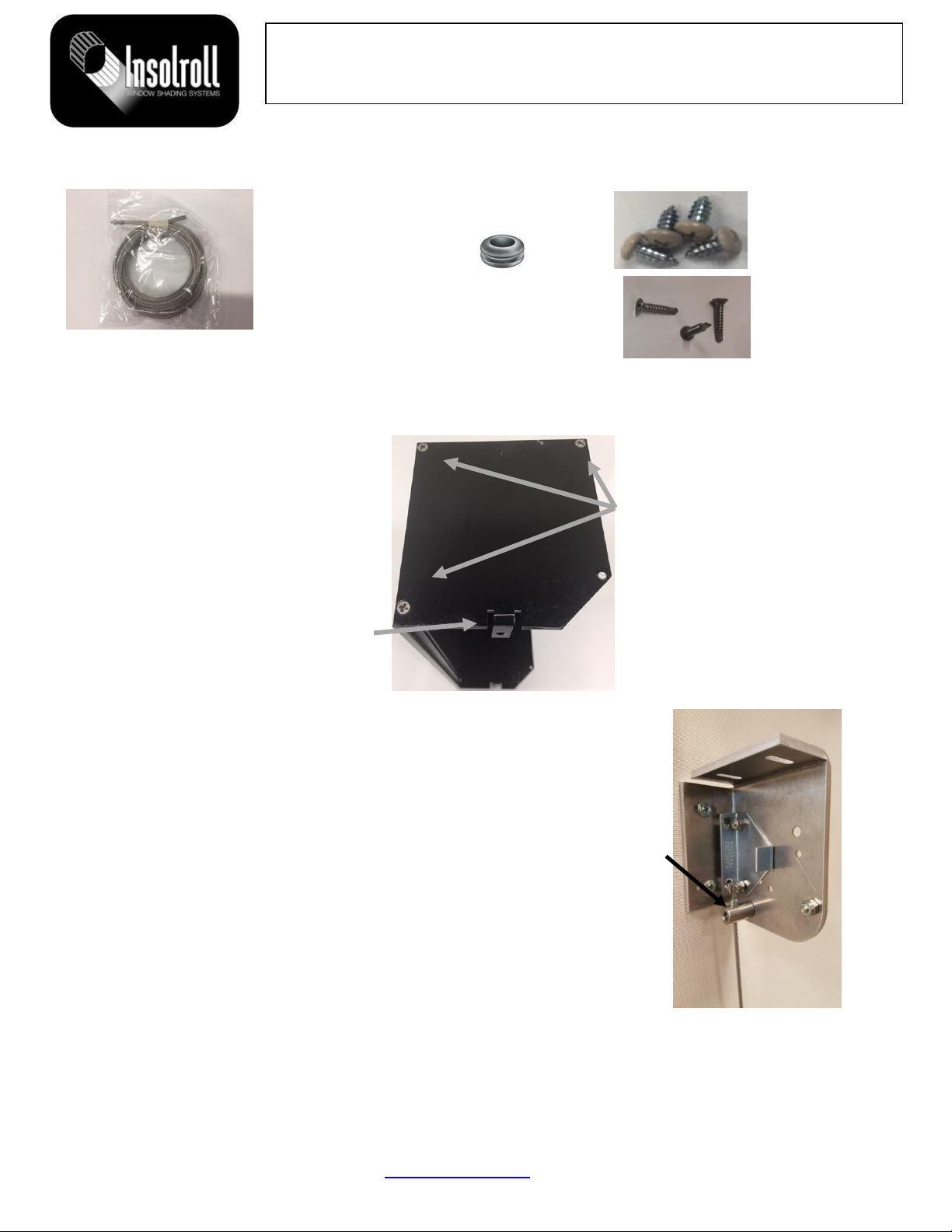
2.2 Shipped Components.....................................................................................................................3
2.2 Shipped Components (Continued)................................................................................................. 4
3.0 Assembly and Installation Instructions.............................................................................................. 4
3.1 End Plate Assembly....................................................................................................................... 4
3.2 Upper Cable Guide ........................................................................................................................ 4
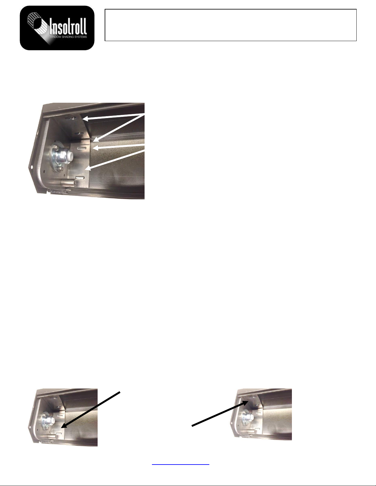
3.3 Bracket Hole Marking on Back Cover........................................................................................... 5
3.3A Motor or Clutch and Idler Bracket Marking........................................................................... 5
3.3B Pre-Drilling Bracket and Motor Wire Holes........................................................................... 5
3.4 Back Cover Installation.................................................................................................................. 5
3.5 Bracket Installation........................................................................................................................ 5
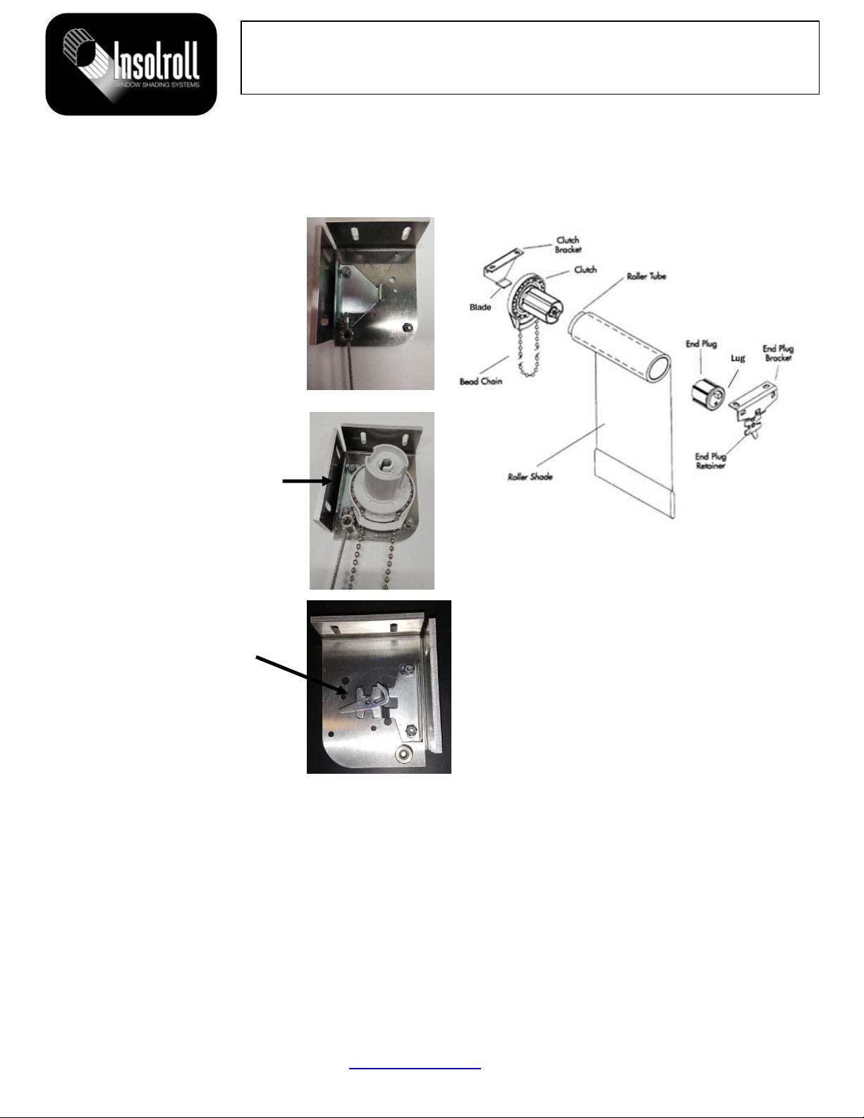
3.6 Shade Installation........................................................................................................................... 6
3.6.A Clutch Operator...................................................................................................................... 6
3.6.B Motor Operator....................................................................................................................... 7
3.7 Hembar Installation........................................................................................................................ 8
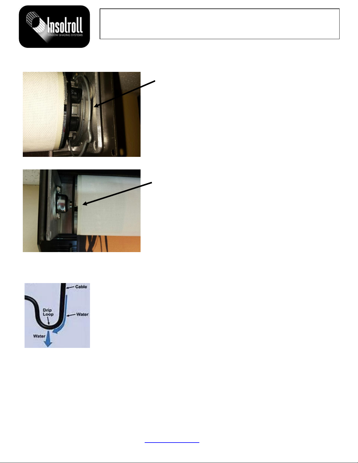
3.8 Cable, Lower Cable Guide, and Deck Mount Installation............................................................. 8
3.8 Cable and Lower Cable Guide Installation (Continued)................................................................ 9
3.9 Chain Guide Installation................................................................................................................ 9
3.9 Chain Guide Installation (Continued).......................................................................................... 10
4.0 Final Adjustments............................................................................................................................ 10
4.1 Setting Motor Limits.................................................................................................................... 10
4.2 Troubleshooting –Telescoping Shade Adjustment.....................................................................10
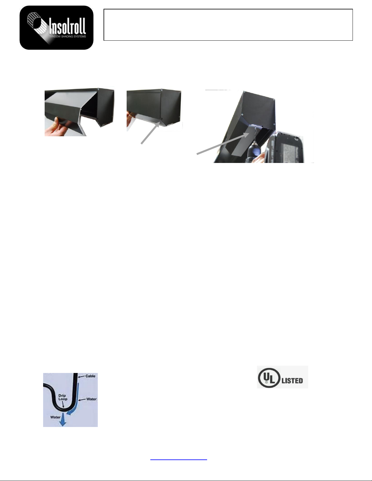
5.0 Front Cover Installation................................................................................................................... 11
6.0 Important Notes for the Electrician.................................................................................................. 11

Page 2 of 11
For more assistance: Insolroll, Inc. www.Insolroll.com 800- 447-5534 Version 02
Oasis® 2700 Patio Shade
Installation Instructions
The Oasis® 2700 Patio Shade system is available in a complete head box with a cable guide and two
types of operators (clutch or motorized). This document provides installation instructions for all shade
systems.
Order height is defined as the distance from the top of the back cover to the bottom of the cable
guide. Verify the window opening versus the shade order size before installation.
1.0 Tools
Screw gun with Phillips head bit extender; Hex nut driver (7 mm); Standard and Phillips head
screwdriver; wire strippers/cutters; pliers or channel locks; level; AC motor test switch; tape measure;
3⁄16 inch drill bit; 3⁄8 inch drill bit, Duct tape.
2.0 Traditional Head Box
2.1 Mounting Options
Cable wall mount and cable deck mount is an option for manual and motor applications.

Page 3 of 11
For more assistance: Insolroll, Inc. www.Insolroll.com 800- 447-5534 Version 02
Oasis® 2700 Patio Shade
Installation Instructions
2.2 Shipped Components
The roller shade (tube, fabric, and clutch or motor) rests in the back cover. The front cover rests in the
back cover.
Depending on the application, the following components are included in the shipment:
Left and right end plates, fully assembled idler bracket, fully assembled motor bracket or, fully
assembled clutch bracket, hembar, grommet, cable guide components, and extra end plate screws.
Clutch Operator
Motor Operator
Front cover
Assembled
Motor
Mount
Bracket
Left
End
Plate
Back cover
Assembled
Clutch
Idler
Bracket
Right
End
Plate
Right
End
Plate
Assembled
Clutch
Bracket
Front Cover
Screws
End Plate
Screws
Deck
Mount
Cable
Bracket
Surface
Mount
Cable
Bracket
Cable
Guide
and
Screw
Assembled
Spring Idler
Bracket
Assembled
Motor
Bracket

Page 4 of 11
For more assistance: Insolroll, Inc. www.Insolroll.com 800- 447-5534 Version 02
Oasis® 2700 Patio Shade
Installation Instructions
2.2 Shipped Components (Continued)
3.0 Assembly and Installation Instructions
3.1 End Plate Assembly
3.2 Upper Cable Guide
The cable guide is shipped in a kit with deck mount and/or surface mount
hardware. Mount the cable guide to each bracket using the supplied M6 Phillips
flat head screw .
.
One end of the supplied cable is crimped with a metal sleeve. Feed the un-
crimped end of the cable through the top of cable guide so that the crimped end
of the cable rests on the cable guide.
Repeat this process for the other bracket. The clutch operator bracket is shown
in the picture to the right.
Cable Tension
Lock
Components
End plates are not attached to the
back cover prior to shipment.
Place the back cover on a flat, clean
surface (cardboard box, saw horses,
or other).
Align the end plates so the tangs are
facing each other.
The tang faces toward the inside of
the head box for the left end plate
shown below.
Carefully secure each
end plate to the back
cover with three painted,
#6 by ¾ inch stainless
steel sheet metal screws
(supplied).
End Plate
Screws
Grommet
Cover
Plate
Screws

Page 5 of 11
For more assistance: Insolroll, Inc. www.Insolroll.com 800- 447-5534 Version 02
Oasis® 2700 Patio Shade
Installation Instructions
3.3 Bracket Hole Marking on Back Cover
Prior to marking the motor and idler bracket holes, plan the location of the power cable for motorized
shades.
3.3A Motor or Clutch and Idler Bracket Marking
3.3B Pre-Drilling Bracket and Motor Wire Holes
Pre-drill all the bracket holes using a 3⁄16 inch drill bit. The resulting hole will accept a #10 screw (not
provided).
Mark and drill a hole using a 7/16 inch drill bit either through the motor bracket and end plate
(recommended) or through the top or the back of the back cover for future routing of the motor power
wire. A supplied grommet fits in the back cover or end plate. Insert the grommet depending on the
application.
3.4 Back Cover Installation
Measure the height and width opening, and verify window dimensions. Confirm order size.
Mark back cover location for intermediate mounting points. Recommended spacing for intermediate
mounting points is four to six feet apart depending on width of the back cover.
Pre-drill the marked locations using a 3/16 inch drill bit for easier installation.
Secure the back cover to the mounting surface in the pre-drilled holes using #8 x 2 inch or longer
pan-head screws (not provided). Ensure that the back cover is level. Be careful not to over-tighten
screws as this may cause damage to the back cover.
3.5 Bracket Installation
Screw brackets to the mounting surface through the back cover with #10 x 1 ½ inch or longer pan-
head screws (not provided). Other screw types might be required depending on mounting surface.
Align the motor/clutch and idler bracket so both
flanges contact the back cover and the face of the
bracket is seated against the end plate.
Mark the two oval screw hole locations on the back
cover for either surface mount or ceiling mount.
The idler bracket is shown in the picture to the left.
Surface mount bracket
Ceiling mount bracket

Page 6 of 11
For more assistance: Insolroll, Inc. www.Insolroll.com 800- 447-5534 Version 02
Oasis® 2700 Patio Shade
Installation Instructions
3.6 Shade Installation
3.6.A Clutch Operator
Due to the design of the clutch bracket, the clutch can only fit on the blade in one orientation.
Remove the protective wrapping from the shade.
Install the shade by pushing
the clutch directly onto the
blade of the bracket.
Install the clutch so the chain
hangs straight down.
Lower the lug of the end plug
onto the “V” of its bracket.
The roller shade should fit
securely in the idler bracket,
with just a little play.
Rotate the riveted retainer
portion to lock the lug in
position.

Page 7 of 11
For more assistance: Insolroll, Inc. www.Insolroll.com 800- 447-5534 Version 02
Oasis® 2700 Patio Shade
Installation Instructions
3.6.B Motor Operator
Remove the motor retainer clip from the motor
mount.
Install the shade into the head box by inserting the
spring idler into the spring idler bracket,
compressing the spring, and inserting the motor
drive into the motor drive bracket ensuring that the
motor limit buttons are accessible as required.
Remove the plastic sleeve protecting the shade
Slide the power wire through the previously drilled
hole, so it does not interfere with the shade
operation.
Ensure there is an adequate drip loop length so no
condensation can travel to the motor head. Refer to
the section named Important Notes for Electrician
at the end of this document
Re-attach the motor retainer clip.
Remove the protective wrapping from the shade.
Connect the motor power cable to a UL listed
switch, connector, junction box, and/or test switch
(not included) that supports 110V AC operation.
Refer to the programming instructions included with
product shipment for AC and ACR motors.

Page 8 of 11
For more assistance: Insolroll, Inc. www.Insolroll.com 800- 447-5534 Version 02
Oasis® 2700 Patio Shade
Installation Instructions
3.7 Hembar Installation
3.8 Cable, Lower Cable Guide, and Deck Mount Installation
Cable and lower cable guide installation is required for both operator (clutch or motor)
and idler bracket.
Remove cable guide brackets (either surface mount or deck mount) from the plastic
bag.
For a surface mount application, attach surface mount brackets at bottom of the
shade. The surface mount bracket is installed with the mounting leg facing up or down depending
upon installation requirements.
For a deck mount application, attach deck mount brackets to the deck surface at the bottom
of the shade location.
Vertically align the cable guide brackets with the upper cable guide hole in the operator and idler
bracket.
Roll the shade down Insert
hembar into the hem pocket
at the bottom of the fabric.
Hembar pop rivets face
toward the back.
Slide cable through hembar
cable guide inserts
Remove
threaded
cable lock
assembly
from plastic
bag.
Remove the
upper nut.
Insert
threaded
assembly into
bracket hole.
Re-attached
the upper nut
and tighten
the lower nut
to expose the
maximum
amount of
thread length
for cable
tension
adjustment.
Upper
Nut
Lower
Nut
7 mm
bolt
Copper
Sleeve

Page 9 of 11
For more assistance: Insolroll, Inc. www.Insolroll.com 800- 447-5534 Version 02
Oasis® 2700 Patio Shade
Installation Instructions
3.8 Cable and Lower Cable Guide Installation (Continued)
Loosen the upper nut and tighten the lower nut to adjust the cable tension.
Do not over tighten. Re-tighten the upper nut.
After tightening the cable, trim excess cable below cable lock with diagonal pliers (leave a minimum
of 1" of cable exposed).
3.9 Chain Guide Installation
Metal Select Chain Guide is a chain tension device designed for inside or outside mounts.
Pull the cable taut beside the surface or deck mount
bracket.
Cut the bottom of the cable as shown.
Remove the sheathing off the cable with a 12-gauge wire
stripper.
Slide the copper sleeve up on the cable until it stops in the
cable tension lock.
Using a pair of pliers, pull cable taut and tighten the 7 mm
bolt. This screw must be completely tight to crush the
copper sleeve in cable lock.
A
a
The installer must release and install this chain guide for the shade to be
operational.
The chain is inserted through the chain guide and connected at the factory prior
to shipment.
Squeeze both flanges to open the chain guide then slide the chain guide down
to the bottom of the chain loop.
Mount the chain guide so there is some slack in the chain so it is easier to
lower and raise the shade. With both flanges open, secure the chain guide by
installing the lower screw (#8 self-tapping screw provided).
If the chain guide is not opened before attaching it to the mounting surface, or
the top screw is attached first, the chain will over-tighten and may make shade
operation more difficult.
The #8 self-tapping mounting screws (provided) are designed for installation in
wood trim, drywall, or aluminum mullion.
After attaching the bottom screw, operate shade to ensure smooth operation.
Use a 3 ½” extended screw bit to ensure the bit does not catch on the chain.
Attach the top screw through the chain guide opening.
Attach chain stops for upper and lower limits of the shade.

Page 10 of 11
For more assistance: Insolroll, Inc. www.Insolroll.com 800- 447-5534 Version 02
Oasis® 2700 Patio Shade
Installation Instructions
3.9 Chain Guide Installation (Continued)
Young children can wrap cords
around their necks and STRANGLE.
● Keep all window cords well out of the
reach of children.
● Move all cribs, beds, furniture and toys
away from windows with cords.
4.0 Final Adjustments
4.1 Setting Motor Limits
Refer to the Radio Programming or Limit Switch Setting instructions for motorized shades. Run the
shade up and down to insure smooth operation before tightening sidetrack screws. Re-measure
tracks at top, middle, and bottom. Check sidetracks with a level to make sure they are plumb.
Tolerances are very tight.
Set up and down limit as required. Remove the test switch and connect motor power wire.
4.2 Troubleshooting –Telescoping Shade Adjustment
To adjust shades for telescoping (excessive horizontal movement of fabric while shade rolls up on the
tube), roll the shade all the way down so the tube is exposed (this will require adjustment of the down
limit).
Place a 4” piece of tape (2”-4” in from the end of shade) on the side of the tube opposite of the
direction the fabric is moving.
Run the shade up. If shade still telescopes, repeat the process. The correct amount of tape can only
be determined by trial and error.
Re-set the down limit after completing shade adjustments.

Page 11 of 11
For more assistance: Insolroll, Inc. www.Insolroll.com 800- 447-5534 Version 02
Oasis® 2700 Patio Shade
Installation Instructions
5.0 Front Cover Installation
Insert the front cover tongue into the back cover groove.
After correctly inserting the front cover in the groove, the front cover will stay engaged as it closes.
If accessible, screw the end plate to the front cover.
For inside mount application and end plate screw holes are
not accessible, secure the front cover to the end plate tang.
Roll the shade down to the lower limit. Drill a hole in the front cover through the end plate tang with a
1⁄8 inch bit . Next, secure the front cover with a 3⁄8 inch painted sheet metal screw (supplied).
For wider shades, the two installers are positioned approximately 1⁄3 the distance from each end to
ease the installation of the front cover.
6.0 Important Notes for the Electrician
An Underwriters Lab (UL) Listed cable clamp or cable gland must be used that is suitable for the
diameter of the cable. The outside diameter of the motor cable is nominally 0.340 inches (8.64mm).
This will ensure that the connection between the motor cable and the junction box is stable and
reduces strain on the conductors.
Any switch, connector, and/or junction box should be UL Listed.
For motorized shades provided with a NEMA 5-15P plug cap, the plug cap must be inserted into a
grounded receptacle. “To reduce the risk of electrical shock, this equipment has a grounding type
plug that has a third (grounding) pin. This plug will only fit into a grounding type outlet. If the plug
does not fit into the outlet, contact a qualified electrician to install the proper outlet. Do not change the
plug in any way.”
Any electrical wiring that is designed to be permanent shall be employed as required by local codes.
Ensure there is adequate drip loop length so no condensation can travel to the motor head. A drip
loop example is shown below:
Insolroll has been granted a UL Listing
for complete motorized shade systems
including any of six upgraded motors
(Model #s STD-AC, STD-ACR,
STD-AC-ILT, IQM-AC, IQM-ACR, and
IQM-AC-ILT).
Other manuals for Oasis 2700
1
Table of contents
Other Insolroll Patio Furniture manuals
Popular Patio Furniture manuals by other brands

Costway
Costway GT4015 manual

AsVIVA
AsVIVA RedNeck GAL2 manual

Home Decorators Collection
Home Decorators Collection YJAUC-171S Use and care guide

Alice's Garden
Alice's Garden PYLA manual

Garden Oasis
Garden Oasis JDC-6525A owner's manual

Backyard Creations
Backyard Creations UMB-952371 Assembly & care instructions

Safavieh Outdoor
Safavieh Outdoor Colley PAT7722 quick start guide

Coolaroo
Coolaroo EUCALYPT Assembly Guide and Operating Instructions

PATIOJOY
PATIOJOY HW70915 Instruction booklet

Uberhaus
Uberhaus 77735156 Operator's manual

Living & Co
Living & Co L&C DELUXE HANG UMBRELLA 2.95M instruction manual

Blumfeldt
Blumfeldt Bayonne manual