Insta Graphic Systems 718 User manual

MODEL
718/728/828
MNL90002
07/08/03 Rev. E
Operation and Maintenance Manual

THIS MACHINE IS DESIGNED TO BE OPERATED BY ONE OPERATOR ONLY
- 2 -
Congratulations!
Your selection of the Insta Graphic Systems (IGS)
heat seal machine is a sound business decision.
IGS equipment is the result of the highest quality
engineering and time-tested design. Your new
machine combined with IGS's reputation of
innovation in the heat-sealing field, insures the
continuing capability of delivering the best
decorated substrates possible.
This manual describes installation, operation, and
maintenance procedures for your new model
machine, as well as easy to use instructions for
on-the-spot maintenance.
Your machine will have a long trouble-free life.
Read this manual. Keep it with your machine; it's
your key to proper operation and lasting service.
Installation
DOMESTIC - 700 SERIES
Use a separate 15 amp AC circuit.
Only industrial extension cords with
proper wire size should be used: size
16/3 wire for distances up to 25 feet,
and size 14/3 for distances up to 50
feet.
INTERNATIONAL - 700 SERIES
Use a designated 16-amp AC cir-
cuit. Only industrial extension
cords with proper wire size (2.5 sq.
mm) shall be used.
DOMESTIC - 800 SERIES
Use a separate 230/240 20-amp AC
circuit. Only industrial extension
cords with proper wire size should
be used: size 14/3 wire for distances
up to 25 feet, and size 12/3 for
distances up to 50 feet.
INTERNATIONAL - 800 SERIES
Use a designated 20-amp AC cir-
cuit. Only industrial extension
cords with proper wire size (3.3 sq.
mm) shall be used.
Limited Machine Warranty
Insta Graphic Systems (IGS) warrants this heat
seal machine, when operated under normal con-
ditions, to be free from manufacturing defects in
material and workmanship for a period of one
year on parts (lifetime on the upper heating
element) and 90 days on labor from the invoice
date.
This warranty will be effective only when IGS
authorizes the original purchaser to return the
product to the factory in Cerritos, California
freight prepaid, and only when the product upon
examination has proven to be defective.
This warranty does not apply to any machine
that has been subjected to misuse, negligence or
accident.
IGS shall not be liable for the injury, loss or dam-
age, direct or consequential, arising out of the use
or the inability to use the product.
No claim of any kind shall be greater in amount
than the sale price of the product or part to
which claim is made.
This is the sole warranty given by the company, it is
in lieu of any other warranties, expressed or implied,
in law or in fact, including the warranties of
merchantability and fitness for a particular use, and
is accepted as such by the purchaser in taking delivery
of this product.
Specifications
Voltage 115/120 Volts AC 50/60 Hertz
Model 718 Wattage 1500 Watts
Model 728 Wattage 1750 Watts
Voltage 230/240 Volts AC 50/60 Hertz
Model 718 Wattage 1500 Watts
Model 728 Wattage 2200 Watts
Model 828 Wattage 3300 Watts
Weight Model 718 132 Pounds (59.9 KG)
Weight Model 728 142 Pounds (64.5 KG)
Weight Model 828 215 Pounds (97.6 KG)
FOR USE BY QUALIFIED SERVICE PERSONNEL ONLY
- 3 -
Operation
1. It is recommended that you review the "How
to Apply Instructions" (in our Product
Information Sheet) before beginning heat-
sealing operations.
2. Push ON/OFF switch to ON position.
3. Set desired temperature.
4. Allow the machine to warm up until the
selected temperature is reached.
5. Set the desired pressure by adjusting the air
pressure regulator.
6. Select the desired timing cycle.
7. Place the substrate on lower platen,
smoothing out all wrinkles.
8. Position transfer or lettering on substrate.
9. Swing the upper platen into position
directly over the lower platen.
NOTE
For operator safety the machine is de-
signed not to operate unless the upper
platen is in the extreme left hand or
right hand position.
10. Depress both start buttons, one on each side
of the machine, simultaneously. At this point the
machine operation is fully automatic. The upper
platen moves downward, seals the transfer to the
substrate and then releases automatically at the
end of the selected timing cycle.
CAUTION
Do not place hands between the platens
after activating.
11. Swing away the upper platen to the opposite
side and remove substrate.
NOTE
Another substrate may be prepared on
the unused platen during the sealing
operation of the used platen.
12. The DISENGAGE button may be pushed at
anytime to deactivate the machine.
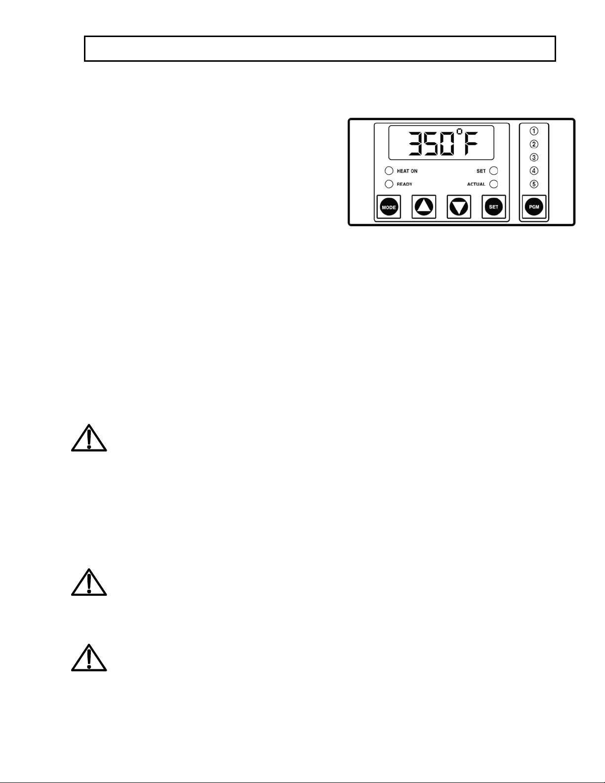
Solid State Controller
This controller has four (4) control features:
1. Temperature - Temperature may be set from
125-450°F (52-232°C)
2. Time - Time may be set from 1 second to 10
minutes
3. Counter - Cycle counter counts the number
of applications from 1 to 9999 (see
Additional Notes - Counter)
4. Presets - Five (5) presets that can be
programmed by the user. Each preset will
retain a temperature and time setting, i.e.
Program #1 could be set for 325°F and 10
seconds while Program #2 could be set for
375°F and 15 seconds. Once the five presets
have been programmed, the user need only
press the PGM button several times until
the desired program is selected. The lit LED
above the PGM button indicates the
selected program. Note: there is also a sixth
setting that is indicated by no lit LED's.
Controller Operation
1. Select the desired preset program by
pressing the PGM button until the LED
above the PGM button indicates the desired
setting.
2. If a setting other than the programmed
presets are desired, press the PGM button
until none of the LED's above the PGM
button are lit.
3. Changing Temperature
• Press the MODE button until
temperature is displayed.
• Press and hold SET button in while
pressing the UP (↑) or DOWN (↓)
arrow buttons to the desired
temperature setting.
FOR USE BY QUALIFIED SERVICE PERSONNEL ONLY
- 4 -
4. Changing Time
• Press the MODE button until time is
displayed.
• Press and hold SET button in while
pressing the UP (↑) or DOWN (↓)
arrow buttons to the desired timer
setting.
NOTE
The DISENGAGE switch (located in
the center of the instrument panel) may
be pushed at any time to deactivate the
machine. The cycle will stop
immediately, and the timer will reset.
5. Allow the machine to warm up until the
selected temperature is reached.
6. Set the desired pressure by adjusting the air
pressure regulator.
7. Place the substrate on lower platen.
8. Position transfer or lettering on substrate.
9. Swing the upper arm into position directly
over the lower platen.
NOTE
For operator safety the machine is de-
signed not to operate unless the upper
arm is directly over one of the lower
platens.
10. Depress both start buttons simultaneously.
At this point the machine operation is fully
automatic. The lower platen moves upward,
seals the transfer to the substrate, and then
releases automatically at the end of the
selected timing cycle.
11. Swing the upper platen away from the lower
platen and remove the substrate.
NOTE
When the machine is operating with
none of the LED's lit, i.e. no presets,
the time and temperature WILL BE
SAVED even if the power is turned off.
The presets will also be saved when the
power is turned off
Setting the Presets
1. Push and hold both the MODE and PGM
buttons for 3-5 seconds until one of the
programs LED's starts to blink. This is the
programming mode.
2. A blinking LED above the PGM button
indicates which preset is active.
3. Select a program (1,2,3,4,or 5) by pressing the
PGM button.
4. Setting Temperature
• Press the MODE button until temperature
is displayed.
• Press and hold SET button in while
pressing the UP (↑) or DOWN (↓) arrow
buttons to the desired temperature
setting.
NOTE
If a Fahrenheit/Celsius change is
desired, see Additional Notes -
Temperature.
5. Setting Time
• Press the MODE button until time is
displayed.
• Press and hold SET button in while
pressing the UP (↑) or DOWN (↓) arrow
buttons to the desired timer setting.
6. Repeat steps 3-5 until all five (5) presets have
the desired preset (temperature/time cycle).
7. Push and hold both the MODE and PGM
buttons for 3-5 seconds to exit the
programming mode.
NOTE
When in the normal mode, none of
the five program LED's will be
blinking and the user cannot change
the time and temperature for any of the
five presets.
ADDITIONAL NOTES:
Temperature
Fahrenheit/Centigrade (Celsius) Conversion
1. Push and hold MODE and PGM buttons for
3 seconds to enter the programming
mode.
2. Push the Mode button until the
temperature is displayed, with the SET
button depressed, push and hold the MODE
button for 3-5 seconds. To exit the
programming mode, push and hold
MODE and PGM buttons for 3-5 seconds.

FOR USE BY QUALIFIED SERVICE PERSONNEL ONLY
- 5 -
Timer
• The controller has a count down timer,
which automatically disengages (opens)
the machine at the completion of the
application.
• Timer display is minutes:seconds. Range
is 00:00 to 10:00, Colons (:) flash while
timer is running.
NOTE
The DISENGAGE switch (located in
the center of the instrument panel) may
be pushed at any time to deactivate the
machine. The cycle will stop
immediately, and the timer will reset.
Counter
The controller has a built in cycle counter.
• Press MODE button until the counter is
displayed.
• Counter display range is 0000 to 9999.
• Reset Cycle Counter
o Press MODE button to display the
counter reading.
o Push and hold both UP (↑) and
DOWN (↓) arrow buttons for three
seconds until the counter resets to
zero (0000) on the display.
Preventive Maintenance Suggestions
The IGS heat seal machines are relatively
maintenance free. For long trouble-free life, the
following preventive maintenance instructions
should be followed:
1. Do not heat seal items such as buttons, pins,
snaps, or zippers, which tend to cut the
silicone rubber pad or scratch the Teflon heat
platen.
2. Periodically clean the Teflon-coated heat
platen with a non-abrasive piece of cloth.
Stubborn stains may be cleaned, when
platen is cool, with mineral spirits.
3. When the heat platen is hot and not in use,
keep in open position (away from the silicone
rubber pads).
4. To prevent soiling of substrate, periodic
wiping of the entire exterior machine,
including platens, with a clean rag is
recommended. If necessary, use mineral
spirits for cleaning a cold machine. Since
mineral spirits are flammable, use precautions
and keep away from sparks, flame, or hot heat
platen.
5. The machines require periodic lubrication
with a high-temperature, non-melting grease
(MPPL023). Lubricate the post and heat
platen pivot pin depending upon usage.
(Once every month if used continuously.)
NOTE
Wipe off any excess oil or grease.
General Maintenance
It is recommended that you have the following
items available:
A. Regular screw driver
B. Phillips head screw driver
C. Small adjustable wrench
D. Needle nose pliers with insulated
handle
E. Set of Allen wrenches
F. Grease gun
G. Special high temperature grease
(MPPL023)
With the above items you should be able to
accomplish most repairs.
WARNING
Power cord replacement should be
supplied from the manufacturer only
(because it requires a specially prepared
cord).
Micro Switch Adjustment
Adjustment of the micro switch must be
accomplished with the power ON. The air may
be on or off but this is incidental.
1. Disconnect power supply; remove instrument
housing (5 screws in font panel) to expose the
micro switch and electrical circuitry.
Reconnect power supply.
NOTE
Avoid touching exposed terminals
FOR USE BY QUALIFIED SERVICE PERSONNEL ONLY
- 6 -
2. Set timer for a one (1) second interval.
3. Swing upper platen into working position
until stop is reached. Back up just enough to
align the outside of front corner of shroud
with edge of lower platen (near swing away
handle). The micro switch must be adjusted
to JUST CLOSE, as upper platen swings to
this position.
4. To change micro switch setting, loosen the
screw on slotted end of micro switch (#36)
and move in desired direction to bring switch
to JUST CLOSED condition (listen for an
audible click from micro switch) and re
tighten screw.

FOR USE BY QUALIFIED SERVICE PERSONNEL ONLY
- 7 -
Safety Summary
WARNING
In case of power cord damage, do
not attempt to repair or replace the
power cord. Contact the manufac-
turer or the local distributor.
WARNING
Fuse F1 is replaceable and must be
replaced with the same rating and
type (1 amp/250V).
WARNING
Avoid touching hot surfaces while
operating the machine.
CAUTION
During normal operation, the base
of the machine needs to be installed
or placed above the wall socket.
CAUTION
The recommended input pressure
shall not exceed 100 psi. The oper-
ating pressure is from 30-100psi.
CAUTION
The operation may be terminated by
pressing the DISENGAGE switch.
CAUTION
The machine is to be operated by
one person only.
CAUTION
When moving, servicing, or
cleaning the machine make sure the
power cord is removed from the wall
socket and sufficient time has been
allowed for the machine to cool
down.
International Symbols
O
Power Off
I
Power On
Hot Surface
Risk of Electrical Shock
Protective Earth Terminal
Start Action
Disengage
Ground
Caution - Warning


MODEL MODEL MODEL MODEL MODEL
718 718 728 728 828
NO PART NAME 115V AC 230V AC 115V AC 230V AC 230V AC
1 SHROUD, HEAT MPSS218 MPSS218 MPSS728 MPSS728 MPSS148
2 SCREW, PAN HD #10 x .75" LG PHIL SH METAL MPSS143 MPSS143 MPSS143 MPSS143 MPSS143
3 INSULATION, FIBERGLASS MPSP251 MPSP251 MPSP254 MPSP254 MPSP254 (2)
5 INSULATORS, SPACER (4/SET) MPSI089 MPSI089 MPSI089 MPSI089 MPSI089
6 POST, GUIDE MPSP084 MPSP084 MPSP084 MPSP084 MPSP084
7 INSULATOR MPSP2310 MPSP2310 MPSP2310 MPSP2310 MPSP2310
8 LIMITER, HI-TEMP. MPPT046 MPPT046 MPPT046 MPPT046 MPPT046
9 SENSOR, RTD MTA90002 MTA90002 MTA90002 MTA90002 MTA90002
10 PIN, PIVOT PLATEN MPSP083 MPSP083 MPSP083 MPSP083 MPSP083
11 SCREW, SET 1/4-20 x .375" LG MHSST142038 MHSST142038 MHSST142038 MHSST142038 MHSST142038
12 PAD, SILICONE RUBBER MPPP030 MPPP030 MPPP031 MPPP031 MPPP825
13 SCREW, SET 5/16-18 x I.00" LG (4/SET) MHSST516181 MHSST516181 MHSST516181 MHSST516181 N/A
14 BREAK-AWAY, LOWER PLATEN MPSP70034 MPSP70034 MPSP70034 MPSP70034 N/A
15 SCREW, SET 3/8-16 x .500" LG MHSST381612 MHSST381612 MHSST381612 MHSST381612 MHSST381612
16 STEM, LOWER PLATEN MH70035 MH70035 MH70035 MH70035 MH70035
17 BOLT, EYE 1/4-20 x 1.00" LG MHBE14201 MHBE14201 MHBE14201 MHBE14201 N/A
18 SPRING MH70002 MH70002 MH70002 MH70002 N/A
19 PIN MH700126 MH700126 MH700126 MH700126 N/A
20 PANEL, INSTRUMENT MPSP728 MPSP728 MPSP728 MPSP728 MPSP728
21 COVER, HOUSING MPSP722 MPSP722 MPSP722 MPSP722 MPSP722
22 SWITCH, START ASS'Y MPPS703 MPPS703 MPPS703 MPPS703 MPPS703
23 SWITCH, DISENGAGE ASS'Y MPPS713 MPPS713 MPPS713 MPPS713 MPPS713
24 CONTROLLER, DIGITAL MPPT752 MPPT752 MPPT752 MPPT752 MPPT752
25 RELAY, SOLID STATE MPSR2450 MPSR2450 MPSR2450 MPSR2450 MPSR2450
26 SCREW, PHILLIPS, PAN HEAD 10-24 x 1.75" LG MHSP1024134 MHSP1024134 MHSP1024134 MHSP1024134 MHSP1024134
27 WIRE HARNESS MPPW731 MPPW732 MPPW731 MPPW732 MPPW732
28 ARM MPSA72821 MPSA72821 MPSA72821 MPSA72821 MPSA82821
29 TRANSFORMER MPPT700 MPPT700 MPPT700 MPPT700 MPPT700
30 COVER, MICRO SWITCH N/A N/A N/A N/A MPSP800
31 BUSHING, POWER DIST. CABLE MPSB072 MPSB072 MPSB072 MPSB072 MPSB073
32 CAP, POST MPSP104 MPSP104 MPSP104 MPSP104 MPSP106
33 SCREW, SOCKET SET 5/16-18 x .750" LG MHSST5161834 MHSST5161834 MHSST5161834 MHSST5161834 MHSST5161834
34 SCREW, SOCKET HEAD 5/16-18 x 1.00" LG MHSSH516181D MHSSH516181D MHSSH516181D MHSSH516181D MHSSH516181D
35 CLAMP, CABLE MHCC12 MHCC12 MHCC12 MHCC12 MHCC34
36 STRAIN RELIEF MPSS164 MPSS164 MPSS164 MPSS164 MH1237
37 SCREW, PHILLIPS PAN HEAD 8-32 x .375" LG MHSP83238 MHSP83238 MHSP83238 MHSP83238 MHSP83238
38 BRACKET, STRAIN RELIEF MPSS161 MPSS161 MPSS161 MPSS161 MPSS162
39 TERMINAL BLOCK (6 POSITION) MPPT705 MPPT705 MPPT705 MPPT705 MPPT705
40 SWITCH, MICRO MPPS044 MPPS044 MPPS044 MPPS044 MPPS044
41 SCREW, BUTTON HEAD 1/4-20 x .625" LG MHSB142058 MHSB142058 MHSB142058 MHSB142058 MHSB142058
42 SCREW, SOCKET SET 5/16-18 x .750" LG MHSST5161834 MHSST5161834 MHSST5161834 MHSST5161834 MHSST5161834
43 COLLAR MPSC72023 MPSC72023 MPSC72023 MPSC72023 MPSC72023
44 SCREW, SOCKET HEAD 5/16-18 x 1.00" LG MHSSH516181 MHSSH516181 MHSSH516181 MHSSH516181 MHSSH516181
45 FUSE (1 AMP 250V) MPPF701 MPPF701 MPPF701 MPPF701 MPPF701
46 FUSE HOLDER MPPF708 MPPF708 MPPF708 MPPF708 MPPF708
47 O-RING, POST MPSS062 MPSS062 MPSS062 MPSS062 MPSS062
48 WIRE, DISTRIBUTION MPPW728 MPPW728 MPPW728 MPPW728 MPPW828
49 HANDLE, SWING AWAY MPSH072 MPSH072 MPSH072 MPSH072 MPSH825
50 SCREW, SOCKET HEAD 1/4-20 x .625" LG MHSSH142058 MHSSH142058 MHSSH142058 MHSSH142058 MHSSH142058
51 KNOB, MUSHROOM MPPK017 MPPK017 MPPK017 MPPK017 N/A
52 SCREW, SOCKET HEAD 1/4-20 x .750" LG MHSSH142034 MHSSH142034 MHSSH142034 MHSSH142034 MHSSH142034
53 BASE ASSEMBLY MPSB721 MPSB721 MPSB721 MPSB721 MPSB826
54 SWITCH, POWER MPPS060 MPPS060 MPPS060 MPPS060 MPPS060
55 GAUGE, AIR MPPA001 MPPA001 MPPA001 MPPA001 MPPA001
56 REGULATOR, PRESSURE ASS'Y MPPA006 MPPA006 MPPA006 MPPA006 MPPA006
57 FITTING INLET MPPF085 MPPF085 MPPF085 MPPF085 MPPF085
58 STRAIN RELIEF, BASE MH3231 MH3231 MH3231 MH3231 MH3231
59 CORD, POWER (USA MODEL) MPPW141 MPPW142 MPPW141 MPPW142 MPPW142
59A CORD, POWER (EUROPEAN MODEL) N/A MPPW202 N/A MPPW202 MPPW202
59B CORD, POWER (GREAT BRITIAN) N/A MPPW203 N/A MPPW203 MPPW203
65 HOSE, AIR ASSY MPPA005 MPPA005 MPPA005 MPPA005 MPPA005
66 SOLENOID, AIR ASS'Y (24V) MPPA024 MPPA024 MPPA024 MPPA024 MPPA024
67 TERMINAL BLOCK (8 POSITION) MPPT709 MPPT709 MPPT709 MPPT709 MPPT709
68 PLATE, ELECTRICAL COVER MPSL716 MPSL716 MPSL716 MPSL716 MPSL717
69 STANDOFF, GUIDE POST MH11072 MH11072 MH11072 MH11072 MH11072
70 SPRINGS, PISTON (3/SET) MPSS137 MPSS137 MPSS137 MPSS137 MPSS137
71 O'RINGS, PISTON (2/SET) MPSR138 MPSR138 MPSR138 MPSR138 MPSR139
72 BUSHING, PISTON GUIDE MPSB070 MPSB070 MPSB070 MPSB070 MPSB070
73 GASKET, PISTON MPSG140 MPSG140 MPSG140 MPSG140 MPSG141
718 728 828 PARTS LIST

MODEL MODEL MODEL MODEL MODEL
718 718 728 728 828
NO PART NAME 115V AC 230V AC 115V AC 230V AC 230V AC
718 728 828 PARTS LIST
74 FITTING, AIR MHAQ69P4X2 MHAQ69P4X2 MHAQ69P4X2 MHAQ69P4X2 MHAQ69P4X2
75 COVER, PISTON MPSH141 MPSH141 MPSH141 MPSH141 MPSA82513
76 SCREW, SOCKET HEAD 1/4-20 x 1.00" LG MHSSH14201 MHSSH14201 MHSSH14201 MHSSH14201 MHSSH14201
77 LABEL, HOUSING OVERLAY MPPL013 MPPL013 MPPL013 MPPL013 MPPL013
A1 UPPER PLATEN ASS'Y MPSP700 MPSP701 MPSP081 MPSP080 MPSP829
A2 LOWER PLATEN ASS'Y MASP008 MASP008 MASP009 MASP009 MASP825
A3 PISTON ROD ASS'Y MPSP139 MPSP139 MPSP139 MPSP139 MPSP149
A4 PISTON REBUILD KIT MPSP712 MPSP712 MPSP712 MPSP712 MPSP812
A5 UPPER PLATEN (WIRING ONLY) MPSP078 MPSP079 MPSP068 MPSP069 MPSP828

®
Service:(800) 426-3609 • Fax:(562) 861-1519 • (562) 861-2566 • Sales:(800) 421-6971 (562) 404-3000 • Fax:(562) 404-3010
http://www.instagraph.com
13925 E. 166th Street • Cerritos CA USA 90702-7900
This manual suits for next models
2
Table of contents
Other Insta Graphic Systems Power Tools manuals


