Instron 2716 Series User manual
100 and 150kN Wedge Grips (Cat. nos. 2716 / 2736)
Operating Instructions M10-14402-EN Revision B
The difference is measurable
®

Electromagnetic Compatibility
Where applicable, this equipment is designed to comply with International Electromagnetic
Compatibility (EMC) standards.
To ensure reproduction of this EMC performance, connect this equipment to a low impedance
ground connection. Typical suitable connections are a ground spike or the steel frame of a
building.
Proprietary Rights Notice
This document and the information that it contains are the property of Illinois Tool Works Inc.
(ITW). Rights to duplicate or otherwise copy this document and rights to disclose the document
and the information that it contains to others and the right to use the information contained
therein may be acquired only by written permission signed by a duly authorized officer of ITW.
Trademarks
Instron®is a registered trademark of Illinois Tool Works Inc. (ITW). Other names, logos, icons
and marks identifying Instron products and services referenced herein are trademarks of ITW
and may not be used without the prior written permission of ITW.
Other product and company names listed are trademarks or trade names of their respective
companies.
Original Instructions
Copyright © 2006 Illinois Tool Works Inc. All rights reserved. All of the specifications shown
in this document are subject to change without notice.
Worldwide Headquarters
Instron
825 University Avenue
Norwood, MA 02062-2643
United States of America
European Headquarters
Instron
Coronation Road
High Wycombe, Bucks HP12 3SY
United Kingdom
Industrial Products Group
Instron
900 Liberty Street
Grove City, PA 16127
United States of America

3
Preliminary Pages
Product Support: www.instron.com
General Safety Precautions
Materials testing systems are potentially hazardous.
Materials testing involves inherent hazards from high forces, rapid motions, and
stored energy. You must be aware of all moving and operating components in
the testing system that are potentially hazardous, particularly force actuators or
a moving crosshead.
Carefully read all relevant manuals and observe all Warnings and Cautions. The
term Warning is used where a hazard may lead to injury or death. The term
Caution is used where a hazard may lead to damage to equipment or to loss of
data.
Instron products, to the best of its knowledge, comply with various national and
international safety standards, in as much as they apply to materials and
structural testing. We certify that our products comply with all relevant EU
directives (CE mark).
Because of the wide range of applications with which our instruments are used,
and over which we have no control, additional protection devices and operating
procedures may be necessary due to specific accident prevention regulations,
safety regulations, further EEA directives or locally valid regulations. The extent
of our delivery regarding protective devices is defined in your initial sales
quotation. We are thus free of liability in this respect.
At your request, we will gladly provide advice and quotations for additional
safety devices such as protective shielding, warning signs or methods of
restricting access to the equipment.
The following pages detail various general warnings that you must heed at all
times while using materials testing equipment. You will find more specific
Warnings and Cautions in the text whenever a potential hazard exists.
Your best safety precautions are to gain a thorough understanding of the
equipment by reading your instruction manuals and to always use good
judgement.
It is our strong recommendation that you should carry out your own product
safety risk assessment.
Preliminary Pages
4M10-14402-EN
Warnings
Hazard - Press the Emergency Stop button whenever you consider that an
unsafe condition exists.
The Emergency Stop button removes hydraulic power or electrical drive from the
testing system and brings the hazardous elements of the system to a stop as
quickly as possible. It does not isolate the system from electrical power, other
means are provided to disconnect the electrical supply. Whenever you consider
that safety may be compromised, stop the test using the Emergency Stop
button. Investigate and resolve the situation that caused the use of the
Emergency Stop button before you reset it.
Flying Debris Hazard - Make sure that test specimens are installed correctly
in grips or fixtures in order to eliminate stresses that can cause breakage of
grip jaws or fixture components.
Incorrect installation of test specimens creates stresses in grip jaws or fixture
components that can result in breakage of these components. The high
energies involved can cause the broken parts to be projected forcefully some
distance from the test area. Install specimens in the center of the grip jaws in
line with the load path. Insert specimens into the jaws by at least the amount
recommended in your grip documentation. This amount can vary between 66%
to 100% insertion depth; refer to supplied instructions for your specific grips.
Use any centering and alignment devices provided.
Hazard - Protect electrical cables from damage and inadvertent
disconnection.
The loss of controlling and feedback signals that can result from a disconnected
or damaged cable causes an open loop condition that may drive the actuator or
crosshead rapidly to its extremes of motion. Protect all electrical cables,
particularly transducer cables, from damage. Never route cables across the
floor without protection, nor suspend cables overhead under excessive strain.
Use padding to avoid chafing where cables are routed around corners or
through wall openings.
5
Preliminary Pages
Product Support: www.instron.com
High/Low Temperature Hazard - Wear protective clothing when handling
equipment at extremes of temperature.
Materials testing is often carried out at non-ambient temperatures using ovens,
furnaces or cryogenic chambers. Extreme temperature means an operating
temperature exceeding 60 °C (140 °F) or below 0 °C (32 °F). You must use
protective clothing, such as gloves, when handling equipment at these
temperatures. Display a warning notice concerning low or high temperature
operation whenever temperature control equipment is in use. You should note
that the hazard from extreme temperature can extend beyond the immediate
area of the test.
Crush Hazard - Take care when installing or removing a specimen,
assembly, structure, or load string component.
Installation or removal of a specimen, assembly, structure, or load string
component involves working inside the hazard area between the grips or
fixtures. When working in this area, ensure that other personnel cannot operate
any of the system controls. Keep clear of the jaws of a grip or fixture at all times.
Keep clear of the hazard area between the grips or fixtures during actuator or
crosshead movement. Ensure that all actuator or crosshead movements
necessary for installation or removal are slow and, where possible, at a low
force setting.
Hazard - Do not place a testing system off-line from computer control
without first ensuring that no actuator or crosshead movement will occur
upon transfer to manual control.
The actuator or crosshead will immediately respond to manual control settings
when the system is placed off-line from computer control. Before transferring to
manual control, make sure that the control settings are such that unexpected
actuator or crosshead movement cannot occur.
Robotic Motion Hazard - Keep clear of the operating envelope of a robotic
device unless the device is de-activated.
The robot in an automated testing system presents a hazard because its
movements are hard to predict. The robot can go instantly from a waiting state
to high speed operation in several axes of motion. During system operation,
keep away from the operating envelope of the robot. De-activate the robot
before entering the envelope for any purpose, such as reloading the specimen
magazine.
Warnings
Preliminary Pages
6M10-14402-EN
Hazard - Set the appropriate limits before performing loop tuning or running
waveforms or tests.
Operational limits are included within your testing system to suspend motion or
shut off the system when upper and/or lower bounds of actuator or crosshead
travel, or force or strain, are reached during testing. Correct setting of
operational limits by the operator, prior to testing, will reduce the risk of damage
to test article and system and associated hazard to the operator.
Electrical Hazard - Disconnect the electrical power supply before removing
the covers to electrical equipment.
Disconnect equipment from the electrical power supply before removing any
electrical safety covers or replacing fuses. Do not reconnect the power source
while the covers are removed. Refit covers as soon as possible.
Rotating Machinery Hazard - Disconnect power supplies before removing
the covers to rotating machinery.
Disconnect equipment from all power supplies before removing any cover which
gives access to rotating machinery. Do not reconnect any power supply while
the covers are removed unless you are specifically instructed to do so in the
manual. If the equipment needs to be operated to perform maintenance tasks
with the covers removed, ensure that all loose clothing, long hair, etc. is tied
back. Refit covers as soon as possible.
Hazard - Shut down the hydraulic power supply and discharge hydraulic
pressure before disconnection of any hydraulic fluid coupling.
Do not disconnect any hydraulic coupling without first shutting down the
hydraulic power supply and discharging stored pressure to zero. Tie down or
otherwise secure all pressurized hoses to prevent movement during system
operation and to prevent the hose from whipping about in the event of a
rupture.
Hazard - Shut off the supply of compressed gas and discharge residual gas
pressure before you disconnect any compressed gas coupling.
Do not release gas connections without first disconnecting the gas supply and
discharging any residual pressure to zero.
Warnings
7
Preliminary Pages
Product Support: www.instron.com
Explosion Hazard - Wear eye protection and use protective shields or
screens whenever any possibility exists of a hazard from the failure of a
specimen, assembly or structure under test.
Wear eye protection and use protective shields or screens whenever a risk of
injury to operators and observers exists from the failure of a test specimen,
assembly or structure, particularly where explosive disintegration may occur.
Due to the wide range of specimen materials, assemblies or structures that may
be tested, any hazard resulting from the failure of a test specimen, assembly or
structure is entirely the responsibility of the owner and the user of the
equipment.
Hazard - Ensure components of the load string are correctly pre-loaded to
minimize the risk of fatigue failure.
Dynamic systems, especially where load reversals through zero are occurring,
are at risk of fatigue cracks developing if components of the load string are not
correctly pre-loaded to one another. Apply the specified torque to all load string
fasteners and the correct setting to wedge washers or spiral washers. Visually
inspect highly stressed components such as grips and threaded adapters prior
to every fatigue test for signs of wear or fatigue damage.
Warnings

Preliminary Pages
8M10-14402-EN

9
Preliminary Pages
Product Support: www.instron.com
Table of Contents
Chapter 1: Introduction . . . . . . . . . . . . . . . . . . . . . . . . . . . . . . . . . . . . . . . . . . . . . . . 11
Purpose . . . . . . . . . . . . . . . . . . . . . . . . . . . . . . . . . . . . . . . . . . . . . . . . . . . . . . . . . . . . . . . . . . 11
Description . . . . . . . . . . . . . . . . . . . . . . . . . . . . . . . . . . . . . . . . . . . . . . . . . . . . . . . . . . . . . . . 14
Components . . . . . . . . . . . . . . . . . . . . . . . . . . . . . . . . . . . . . . . . . . . . . . . . . . . . . . . . . . 14
Functional . . . . . . . . . . . . . . . . . . . . . . . . . . . . . . . . . . . . . . . . . . . . . . . . . . . . . . . . . . . . 15
Chapter 2: Specifications. . . . . . . . . . . . . . . . . . . . . . . . . . . . . . . . . . . . . . . . . . . . . . 17
Grip Specifications . . . . . . . . . . . . . . . . . . . . . . . . . . . . . . . . . . . . . . . . . . . . . . . . . . . . . . . . . 17
Series 2716 Grips . . . . . . . . . . . . . . . . . . . . . . . . . . . . . . . . . . . . . . . . . . . . . . . . . . . . . . 17
Series 2736 Grips. . . . . . . . . . . . . . . . . . . . . . . . . . . . . . . . . . . . . . . . . . . . . . . . . . . . . . 18
Jaw faces. . . . . . . . . . . . . . . . . . . . . . . . . . . . . . . . . . . . . . . . . . . . . . . . . . . . . . . . . . . . . . . . . 18
Chapter 3: Installation . . . . . . . . . . . . . . . . . . . . . . . . . . . . . . . . . . . . . . . . . . . . . . . . 21
Attachment Methods . . . . . . . . . . . . . . . . . . . . . . . . . . . . . . . . . . . . . . . . . . . . . . . . . . . . . . . 21
Installing the Grips . . . . . . . . . . . . . . . . . . . . . . . . . . . . . . . . . . . . . . . . . . . . . . . . . . . . . . . . . 22
Checklist . . . . . . . . . . . . . . . . . . . . . . . . . . . . . . . . . . . . . . . . . . . . . . . . . . . . . . . . . . . . . 22
Procedures . . . . . . . . . . . . . . . . . . . . . . . . . . . . . . . . . . . . . . . . . . . . . . . . . . . . . . . . . . . 22
Replacing Jaw faces . . . . . . . . . . . . . . . . . . . . . . . . . . . . . . . . . . . . . . . . . . . . . . . . . . . . . . . . 23
Equipment . . . . . . . . . . . . . . . . . . . . . . . . . . . . . . . . . . . . . . . . . . . . . . . . . . . . . . . . . . . . 23
Procedure . . . . . . . . . . . . . . . . . . . . . . . . . . . . . . . . . . . . . . . . . . . . . . . . . . . . . . . . . . . . 23
Chapter 4: Operation . . . . . . . . . . . . . . . . . . . . . . . . . . . . . . . . . . . . . . . . . . . . . . . . . 25
Installing a Specimen. . . . . . . . . . . . . . . . . . . . . . . . . . . . . . . . . . . . . . . . . . . . . . . . . . . . . . . 25
Checklist . . . . . . . . . . . . . . . . . . . . . . . . . . . . . . . . . . . . . . . . . . . . . . . . . . . . . . . . . . . . . 26
Procedure . . . . . . . . . . . . . . . . . . . . . . . . . . . . . . . . . . . . . . . . . . . . . . . . . . . . . . . . . . . . 26
Removing a Specimen . . . . . . . . . . . . . . . . . . . . . . . . . . . . . . . . . . . . . . . . . . . . . . . . . . . . . . 27
Checklist . . . . . . . . . . . . . . . . . . . . . . . . . . . . . . . . . . . . . . . . . . . . . . . . . . . . . . . . . . . . . 27
Procedure . . . . . . . . . . . . . . . . . . . . . . . . . . . . . . . . . . . . . . . . . . . . . . . . . . . . . . . . . . . . 27
Chapter 5: Maintenance . . . . . . . . . . . . . . . . . . . . . . . . . . . . . . . . . . . . . . . . . . . . . . 29
Cleaning and Lubrication . . . . . . . . . . . . . . . . . . . . . . . . . . . . . . . . . . . . . . . . . . . . . . . . . . . . 29

Preliminary Pages
10 M10-14402-EN
Checklist . . . . . . . . . . . . . . . . . . . . . . . . . . . . . . . . . . . . . . . . . . . . . . . . . . . . . . . . . . . . . 29
Shear Pin Replacement . . . . . . . . . . . . . . . . . . . . . . . . . . . . . . . . . . . . . . . . . . . . . . . . . . . . . 30
Troubleshooting . . . . . . . . . . . . . . . . . . . . . . . . . . . . . . . . . . . . . . . . . . . . . . . . . . . . . . . . . . . 30
Chapter 6: Parts. . . . . . . . . . . . . . . . . . . . . . . . . . . . . . . . . . . . . . . . . . . . . . . . . . . . . . 33
Replaceable Parts . . . . . . . . . . . . . . . . . . . . . . . . . . . . . . . . . . . . . . . . . . . . . . . . . . . . . . . . . 33
Ancillary Parts . . . . . . . . . . . . . . . . . . . . . . . . . . . . . . . . . . . . . . . . . . . . . . . . . . . . . . . . . . . . . 34

11
Product Support: www.instron.com
Chapter 1
Introduction
This chapter introduces you to the low capacity (24.5 kN to 147 kN [5000 lb to 30000
lb]) Series 2716 and 2736 wedge action grips and describes the grip components.
Illustrations and text detail the grip components and their function.
•Purpose . . . . . . . . . . . . . . . . . . . . . . . . . . . . . . . . . . . . . . . . . . . . . . . . . . . . . . . . . . 11
•Description. . . . . . . . . . . . . . . . . . . . . . . . . . . . . . . . . . . . . . . . . . . . . . . . . . . . . . . . 14
Purpose
Instron Series 2716 and 2736 wedge action grips hold a test specimen between a
stationary load frame member and a force producing crosshead or actuator. Figure 1
and Figure 2 illustrates the grips and their components.
Chapter: Introduction
12 M10-14402-EN
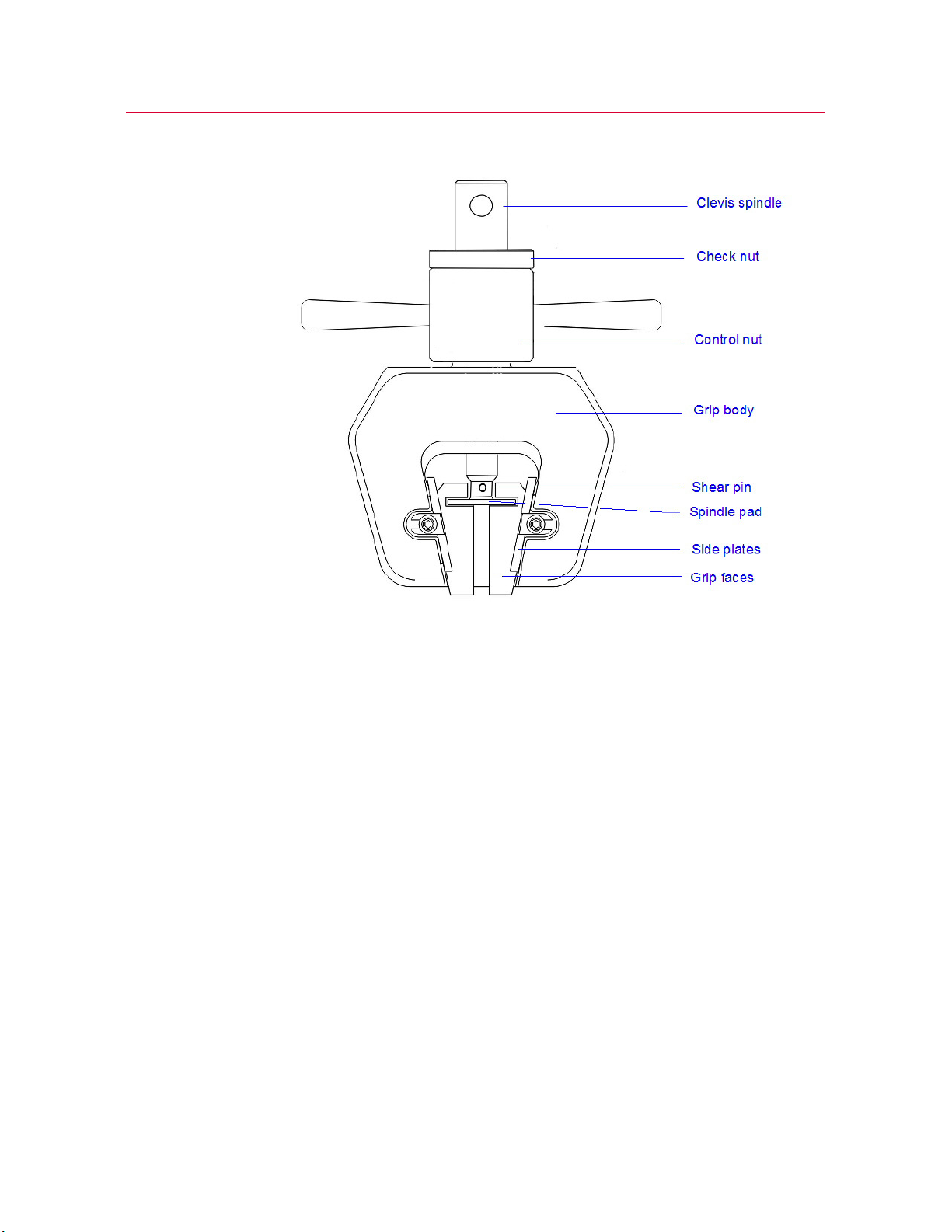
Figure 1. Typical Wedge Grip (Front)
13
Purpose
Product Support: www.instron.com
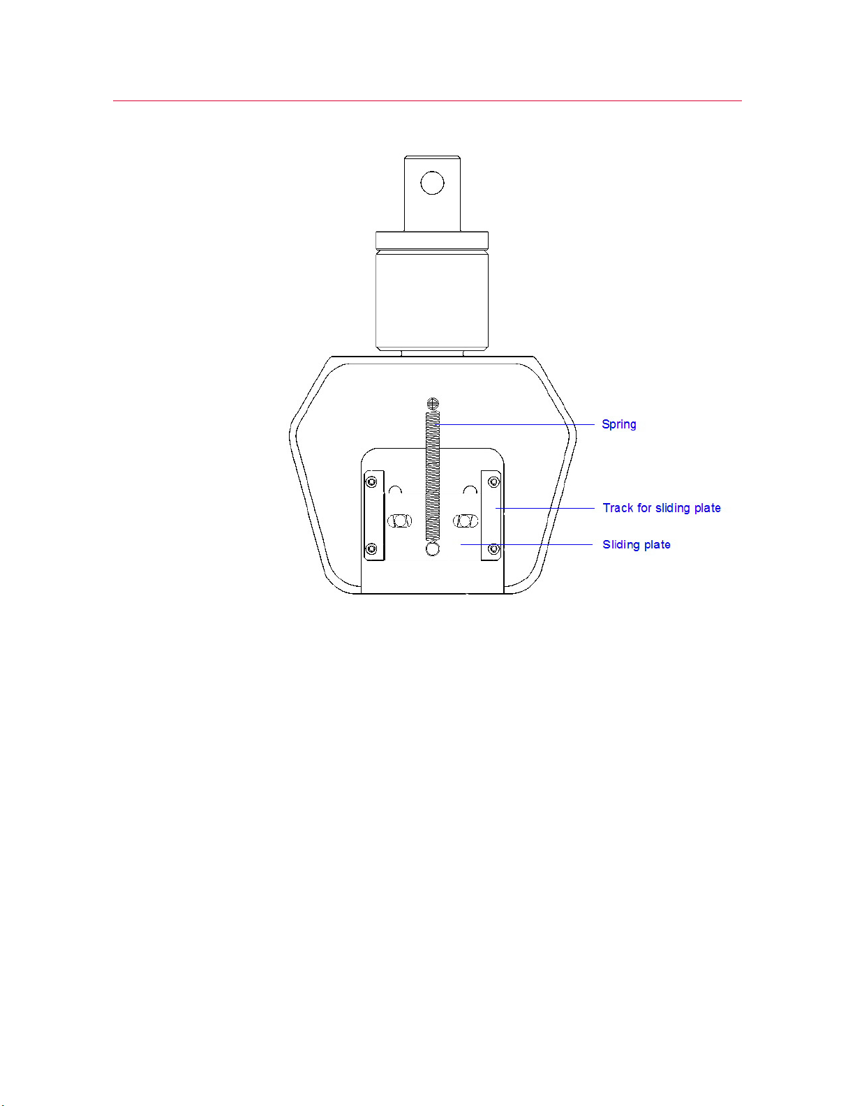
Figure 2. Typical Wedge Grip (Rear)
The grips cover a wide range of common applications in materials testing. The two series
are similar, with the principal difference being that the series 2736 grips are rated for
high temperature use and configured with handles that facilitate their use in high-
temperature cabinets.
The grips are for static tensile testing only. The wedge action design lets the jaw faces
tighten onto a specimen without altering the vertical position of the faces in relation to
the specimen, letting you install a test specimen without exerting a tensile load on it
while tightening the grips. A compressive test load eliminates any gripping force and
causes the specimen to slip from the grips.
The open front design of the grip lets you change the jaw faces to accommodate flat,
round or different size specimens.

Chapter: Introduction
14 M10-14402-EN
Description
Components
The major grip components are the body, control mechanism, and jaw faces.
Body
The machined alloy-steel body has a vertical center bore with an integral threaded stud
extending away from the body. A control nut threads on the stud and a spindle passes
through the bore.
The grip body has a machined open cavity. Each side of the cavity tapers toward the
open end of the body. The jaw faces have a matching taper such that as the faces slide
toward the open end of the cavity, they are forced together and thus provide a gripping
force on a specimen.
Side plates, screwed to the front of the grip body, retain the jaw faces within the cavity.
On the rear of the body, a spring-loaded plate slides in tracks screwed to the body. Pins
in the grip jaws extend through slots in the plate. The spring force on the plate, and
transmitted to the jaw pins, pushes the grip jaws against the tapered sides of the cavity
and also provides a constant retraction force on the grip jaws.
Control Mechanism
The control mechanism consists of a control nut and spindle. The control nut is a short
steel cylinder with a center bore and internal threads. The nut threads onto the body
threads. Handles on the control nut let you easily tighten and loosen the grips.
The spindle is a steel shaft with a one end either threaded or machined to accept a
clevis pin, The other end is machined for a shear pin which secures a flat spindle pad.
The threaded end passes through the control nut. The spindle pad slots into the base of
the jaw faces. Rotation of the control nut moves the grip body while the jaw faces are
held stationary. As the grip body moves, the tapers in the cavity move the grip jaws
laterally to grip or release the specimen without exerting a longitudinal (tensile or
compressive) force on the specimen.
Faces
Various jaw faces are interchangeable in each grip model size, to accommodate a range
of flat or round specimen sizes. There are four jaw faces in each set; a left and right face
for each upper and lower grip.

15
Description
Product Support: www.instron.com
The faces are made of hardened steel and are serrated for maximum gripping
effectiveness. Serrations are either 16 or 25 teeth per inch (tpi). The 16 tpi faces are
preferable for use with most metals since they provide greater penetration into the
specimen and longer wear. The 25 tpi faces are ideal for small diameter, thin, very hard,
or penetration sensitive specimens.
Functional
Closed
When you turn the handles to close the grip on a specimen, the screw action of the
control nut and body threads move the body away from the test specimen and push the
spindle end against the jaw faces. The position of the faces remain vertically fixed,
relative to the specimen, because the body is moving away from the specimen. The anti-
rotation pins prevent the grip from rotating as you tighten the control nut. The angle of
the jaw faces and the body wedges force the faces inward on the specimen until the
face serration bite into the specimen. The gripping force increases during a test as the
system applies more tensile force to the specimen.
Open
When you turn the control handles to open the grip, the screw action of the control nut
moves the body toward the test specimen. The slide plate, under tension from the
spring, applies a force to the grip jaw pins to move the grip jaws away from the
specimen.

Chapter: Introduction
16 M10-14402-EN

17
Product Support: www.instron.com
Chapter 2
Specifications
This chapter details the grip specifications and includes a dimensional drawing of the
grips.
•Grip Specifications . . . . . . . . . . . . . . . . . . . . . . . . . . . . . . . . . . . . . . . . . . . . . . . . . 17
•Jaw faces . . . . . . . . . . . . . . . . . . . . . . . . . . . . . . . . . . . . . . . . . . . . . . . . . . . . . . . . . 18
Grip Specifications
Series 2716 Grips
Table 1 on page 17 details the specifications for the 2716 series of grips.
Table 1. 2716 Series Specifications
Cat. No.
Load
Capacity/
kN (lb)
Temperature
Range/C (F)
Face
Width/mm
(in.) Mount1Weight2
/kg (lb)
Overall
Width3/
mm (in.)
Overall
Length3/
mm (in.)
2716-
002
100
(22,500)
-73 to 250
(-100 to 480)
25.4 (1.0) Type DM40.0
(88.2)
144
(5.67)
254
(10.0)
2716-
003
100
(22,500)
-73 to 250
(-100 to 480)
50.8 (2.0) Type DM60.0
(132.3)
168
(6.63)
254
(10.0)
2716-
008
150
(33,700)
-73 to 250
(-100 to 480)
50.8 (2.0) M48 x 2
Male
Thread
60.0
(132.3)
178 (7.0) 340
(13.5)
1. Refer to Chapter 3- Installation for attachment interface information.
2. Weights shown are total approximate shipping weight per grip pair (less faces)
3. Dimensions shown are approximate overall width and length per grip (less control nut handles and jaw
faces).

Chapter: Specifications
18 M10-14402-EN
Series 2736 Grips
Table 2 on page 18 details the specifications for the 2736 series of grips.
Jaw faces
Jaw faces are available for testing flat or round specimens. Use flat faces for flat
specimens and vee or round groove faces for round specimens. This section details the
various jaw faces available.
Caution
Do not use serrated jaw faces to test specimens with a hardness value greater than
40 Rockwell C.
When testing extremely hard specimens, the jaw face serrations may not adequately
penetrate the specimen surface. Further, hard specimens will cause accelerated wear
of the serrations.
Table 3 on page 19 lists the available jaw faces:
Table 2. 2736 Series Specifications
Cat. No.
Load
Capacity/
kN (lb)
Temperature
Range/C (F)
Face
Width/mm
(in.) Mount1Weight2/
kg (lb)
Overall
Width3/
mm (in.)
Overall
Length3/
mm (in.)
2736-
004
100
(22,500)
-73 to 315
(-100 to 600)
25.4 (1.0) Type DM40.0
(88.2)
144
(5.67)
254
(10.0)
2736-
005
100
(22,500)
-73 to 315
(-100 to 600)
50.8 (2.0) Type DM60.0
(132.3)
168
(6.63)
254
(10.0)
1. Refer to Chapter 3- Installation for attachment interface information.
2. Weights shown are total approximate shipping weight per grip pair (less faces)
3. Dimensions shown are approximate overall width and length per grip (less control nut handles and jaw
faces).

19
Jaw faces
Product Support: www.instron.com
Table 3. Jaw face compatibility
Cat. No. Face Type
Serrations per
in. Specimen Size/mm (in.) Use with grips
2703-001 Flat 16 0 to 6.4 (0 to 1/4) 2716-002 or 2736-004
2703-002 Flat 16 6.3 to 12.7 (1/4 to 1/2) 2716-002 or 2736-004
2703-006 Flat 25 0 to 6.4 (0 to 1/4) 2716-002 or 2736-004
2703-007 Flat 25 6.4 to 12.7 (1/4 to 1/2) 2716-002 or 2736-004
2703-004 Vee 16 7 to 12.7 (9/32 to 1/2) 2716-002 or 2736-004
2703-008 Vee 25 3.5 to 8 (1/8 to 5/16) 2716-002 or 2736-004
2703-009 Vee 25 7 to 12.7 (9/32 to 1/2) 2716-002 or 2736-004
2703-010 Vee 25 12.7 to 19 (1/2 to 3/4) 2716-002 or 2736-004
2703-070 Round 16 12.7 to 15.8 (1/2 to 5/8) 2716-002 or 2736-004
2703-071 Round 16 15.8 to 19 (5.8 to 3/4) 2716-002 or 2736-004
2703-011 Flat 16 0 to 6.4 (0 to 1/4) 2716-003, 2716-008, or
2736-005
2703-012 Flat 16 6.4 to 12.7 (1/4 to 1/2) 2716-003, 2716-008, or
2736-005
2703-013 Vee 25 3.5 to 8 (1/8 to 5/16) 2716-003, 2716-008, or
2736-005
2703-014 Vee 25 7 to 12.7 (9/32 to 1/2) 2716-003, 2716-008, or
2736-005
2703-015 Vee 25 12.7 to 19 (1/2 to 3/4) 2716-003, 2716-008, or
2736-005
2703-072 Round 16 12.7 to 15.8 (1/2 to 5/8) 2716-003, 2716-008, or
2736-005
2703-073 Round 16 15.8 to 19 (5.8 to 3/4) 2716-003, 2716-008, or
2736-005

Chapter: Specifications
20 M10-14402-EN
This manual suits for next models
6
Table of contents
Other Instron Power Tools manuals

Popular Power Tools manuals by other brands

GRAVEDA
GRAVEDA GRASPRESSO GP4-20 instruction manual

Dynabrade
Dynabrade Dynisher 50730 Important operating, maintenance and safety instructions

SW Stahl PROFI Tools
SW Stahl PROFI Tools 26131L instruction manual

Hi-Force
Hi-Force HTW Series Operating instructions manual

Desoutter
Desoutter PT025-L4500-S10S user manual

AFSA
AFSA 1258 manual


Chicago Electric
Chicago Electric 40039 Assembly and operating instructions

Delta Regis
Delta Regis ESB6-RA30 Operation manual

Yokota
Yokota TKA800-C manual

Warn
Warn VANTAGE 4000 Service instructions manual

Narex
Narex ASR 600-3MTB BASIC Original operating manual

Würth
Würth 1952 003 133 Translation of the original operating instructions