Intelix Psychologist User manual

User Manual
Psychologist Series
Remote Monitor Systems
2Psychologist Mixer User Manual
Psychologist Mixer User Manual
2222 Pleasant View Road
Middleton, Wisconsin 53562
(608) 831-0880
Fax (608) 831-1833
http:\\www.intelix.com
Psychologist User Manual
Revision H 0802
2002 Intelix. All rights reserved.
Model/ Serial Number
Crosspoint ROM
Application ROM
PC Diskette
Communication ROM

3
Psychologist Mixer User Manual
Psychologist Mixer User Manual
TABLE OF CONTENTS
Introduction ................................................................................................................. 4
Safety Instruction ...................................................................................................................... 5
Maintainance Guidelines .......................................................................................................... 5
Quick Start ................................................................................................................... 6
System Description............................................................................................................................. 10
Audio Matrix Mixer ............................................................................................................... 10
Front Panel.............................................................................................................................. 10
Rear Panel............................................................................................................................... 10
Signal-to-Noise....................................................................................................................... 12
System Balancing ................................................................................................................... 12
Inputs and Outputs.................................................................................................................. 14
DIP Switch Settings................................................................................................................ 14
Mini-Mixer Remote Controllers .............................................................................. 15
8/1 Mini-Mixer ....................................................................................................................... 16
16/1 Mini-Mixer ..................................................................................................................... 16
16/2 Mini-Mixer ..................................................................................................................... 16
8/2 Mini-Mixer ....................................................................................................................... 16
32/1 Mini-Mixer ..................................................................................................................... 16
Mini-Mixer Configuration...................................................................................................... 17
Status LED.............................................................................................................................. 17
Mini-Mixer location selector .................................................................................................. 18
Mini-Mixer Power .................................................................................................................. 18
ReO Bus Connections.............................................................................................................19
System Installation Reference.................................................................................. 20
AC Power Connection ............................................................................................................ 20
DC Power connection.............................................................................................................20
Audio Input and Output Connections ..................................................................................... 21
Grounding the Minimixer....................................................................................................... 21
Audio Input Impedance .......................................................................................................... 22
Audio Output Impedance........................................................................................................ 22
Recommended Input Connection Configurations .................................................................. 23
Mini-Mixer Connections ........................................................................................................ 24
Adding Mini-Mixers............................................................................................................... 26
Troubleshooting Tips.............................................................................................................. 27
Appendix A Cable Pinouts........................................................................................28
PCD9F Mini-mixer Cable ...................................................................................................... 28
PRJ11/DB9 Mini-mixer Cable ............................................................................................... 28
Appendix B................................................................................................................. 29
Technical Information........................................................................................................................ 29
Warranty.............................................................................................................................................. 30

4Psychologist Mixer User Manual
Psychologist Mixer User Manual
Introduction
This manual describes the components and operations of the Psychologist, a monitor mixing system
based on the standard Intelix Matrix Mixer and Mini-Mixer remote controls. Together we’ll call
them the Psychologist System, or just the system.
This manual explains the features of the Psychologist System, its installation and operation. We
strongly recommend that you use this manual when you install and operate the system.
Each section of the manual describes an important aspect of the Psychologist System.
This introductory section introduces the system, explaining important safety information and describ-
ing maintenance guidelines. The Quick Start section shows you how to install most common Psy-
chologist configurations without having to read the rest of the manual (although we strongly suggest
you read the entire manual before installing your system).
The System Description section describes the hardware components of the system. These devices
include the Matrix Mixer, the Mini-Mixer remote controllers, power supplies and cabling.
The System Installation Reference section explains in detail how to install your Psychologist system,
and how to add Mini-Mixers. You’ll need to use this section if your system is not a common configu-
ration. Troubleshooting information is also provided.
The Technical Information section provides system specifications.
Enjoy your new Intelix Psychologist system!
2222 Pleasant View Road
Middleton, Wisconsin 53562
(608) 831-0880
Fax (608) 831-1833
http:\\www.intelix.com

5
Psychologist Mixer User Manual
Psychologist Mixer User Manual
Safety Instruction
Note: Read all the directions carefully before use.
Take all the precautions usually taken with electrical equipment. To protect both the users and the
equipment:
Grounding
Make sure both the Matrix and the devices connected to it are properly grounded.
Power Supply
Use only the power supply provided by the manufacturer or one that meets the manufacturer’s
specifications.
Cords and Cables
Route all cords and cables so that they will not be tripping hazards nor subject to damage (from
being run over or pinched) that could cause them to become shock hazards. Pay particular attention
to cords at plugs, convenience receptacles, and the point where they enter the Matrix and the Mini-
Mixer remote controls.
Fire
If the Matrix or other electrical equipment catches fire, extinguish the fire using a carbon dioxide
(CO2) extinguisher or any extinguisher rated for electrical fires. Do not use water or a water extin-
guisher.
Electronic devices operate best in clean, well-ventilated environments. The Matrix unit has a greater
than normal density of electronic components, and so generates more heat than the average electronic
device. Place the Matrix where it will be well-ventilated, well away from other heat-generating equip-
ment such as amplifiers.
The Mini-Mixer remote controllers should also be kept clean. Route all cords and cables so that they
will not be tripping hazards nor subject to damage from being run over or pinched. To minimize hum
in the System, avoid placing the remotes and cables near EMF-producing devices such as electrical
motors, fluorescent lights, AC power lines, SCR dimmers, etc.
The remotes may be left connected and powered when not in use.
Maintainance Guidelines

6Psychologist Mixer User Manual
Psychologist Mixer User Manual
Quick Start
This section describes how to get your Psychologist system up and running. This section covers most
typical installations. If your system has any unusual features, or you need to know more about how
your system works, read the chapter associated with each step. For more detailed installation instruc-
tions, see System Installation Reference, on page 20.
1. Connect the Intelix 18 Volt transformer to the AC power connector on the rear of the
Mixer.
Make sure that the flat side of the connector faces down.
2. Plug the 18 Volt transformer into a grounded 110 VAC outlet.
3. Connect audio inputs and outputs.
Each input and output channel uses a triplet Phoenix connector. These connectors can be removed
from the chassis for ease of wiring. The three wires within each signal line must be connected to the
Phoenix connector as shown below.
7
Psychologist Mixer User Manual
Psychologist Mixer User Manual
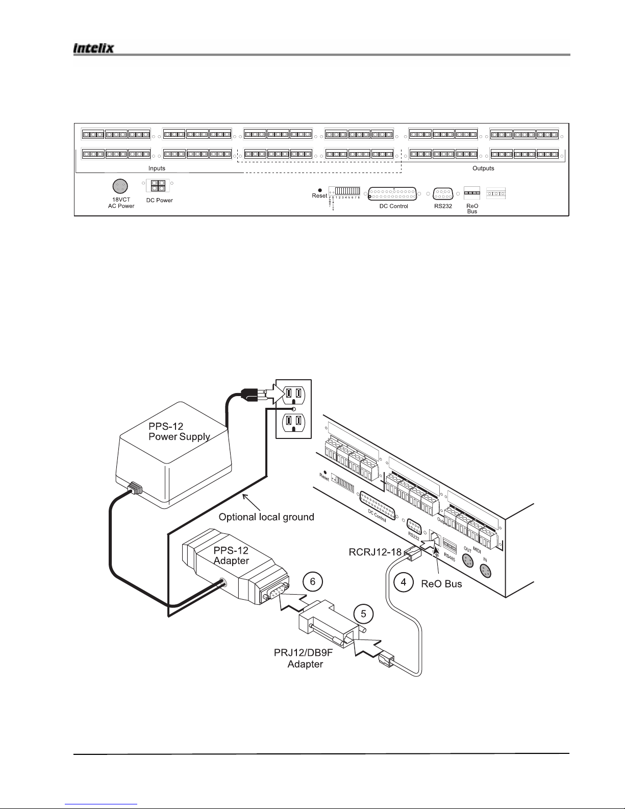
4. Connect the RCRJ12-18cableto the ReOBus connector ontherear panel oftheMatrix Mixer.
The following illustration shows the connections for the steps 4 through 6.
For more information on audio input and output connections, and information on impedance match-
ing and connection configurations, see the Audio Input and Output Connections section on page 21-
23.
Connect the inputs to the blocks on the left of the Matrix unit. Connect the outputs to the blocks on
the right hand side of the Matrix unit. (This illustration shows an 8 x 8 Matrix Mixer. Your system
may be different.)

8Psychologist Mixer User Manual
Psychologist Mixer User Manual
5. Connect the RCRJ12-18cable tothe PRJ12/DB9F adapter.
Becausethe Mini-Mixers usea9-pinD connector cable,you’llneed to usethePRJ12/DB9F adapter
toconvert to theRJ12 connector usedforthe RCRJ12-18cablethat connects tothe Matrix Mixer.
6. Connect the PRJ12/DB9F adapter to the PPS-12 power adapter. Intelix stronglyrecommends
that the PPS-12 is installed as close to the Mini-Mixer remote locations as possible. If the Psy-
chologistmatrixisinstalledinarackroomawayfromthestage/studiolocation,itmaybenecessarytoruna
lengthofCat5 UTP cable tothestage/studiolocationfor connection to thePRJ12/DB9Fadapter. Intelix
suppliesan18"cable,RCRJ12-18,forcloseproximityinstallations.
Connect the PRJ12/DB9F adapter to the PPS-12 adapter. Plug the RCRJ12-18 cable into the PRJ12/
DB9Fadapter andthe ReO porton the rearof the matrix.
7. Connect a PC cable into the free end of the PPS-12 adapter.
Ifyoursystem requires local grounding,connecttheblack lead from thePPS-12adaptorto a local
ground;abuildinggroundasshownoralocalrackground
Plugthe PPS-12 powersupplyinto a grounded110VACoutlet.
Typicallythe PPS-12 power supplygoesintotheseries of PC cablesatthebeginningofthe chain, as shown
intheillustrationbelow.Forotheroptions,orifyoursystemhasmorethaneightMini-Mixers,seetheMini-
MixerPower section onpage18.
VerifythesettingsoftheMini-Mixerlocationselectors(seepage18).

9
Psychologist Mixer User Manual
Psychologist Mixer User Manual
8. Connect the Mini-Mixers one at a time.
ConnecttheMini-Mixerwithlengths of PC cables.TheDB9Fconnectorscanconnecttoeither of the
twointerchangeableportsonthesideoftheMini-Mixers.
Verify that the Mini-Mixer is powered up and communicating with the Matrix Mixer as indi-
cated by a steady-on status LED before connecting the next Mini-Mixer.
For more information on connecting Mini-Mixer, including directions on adding new Mini-
Mixerstothesystem,see the Mini-Mixer Connectionssectiononpage26.
9. Verify system operation. Turn on Audiosourcesand amplifiers.
Listentotheoutputmonitoringdevicesandadjustthe mini-mixervolumecontrols.Youarenowready
forlive,individualmonitoringoftheinputsources.
Ifyour system doesnot seem tobeworking properly, seethe Status LEDsection on page17,and the
Troubleshooting Tipssectiononpage27.

10 Psychologist Mixer User Manual
Psychologist Mixer User Manual
System Description
This section describes the components of your Psychologist System. Read this section to famil-
iarize yourself with the system components before you install your system.
Audio Matrix Mixer
The Psychologist is based on the Intelix Matrix Mixer, which allows audio signals from mul-
tiple sources to be sent to multiple destinations. The Matrix Mixer is designed so that audio inputs
can be independently mixed to any and all outputs simultaneously.
Front Panel
A single LED on the front panel indicates that the Matrix is powered.
Note: The LED is the only reliable indicator of the powered state of the Matrix. There is no
power on/off switch on the Matrix.
Rear Panel
18 VCT 4-pin power receptacle
DC power receptacle
For connection to a DC supply (+/- DC) or batteries.
Reset button
Restarts Matrix microprocessors.
910

11
Psychologist Mixer User Manual
Psychologist Mixer User Manual
Outputs
Stripsof male screw terminal (Phoenix type) connectors. Eachblockaccommodatesfourtriplet
plugs.
Inputs
Strips of male screw terminal (Phoenix type) connectors. Each block accommodates four
triplet plugs.
RS485
Currently unused 3 pin male connector. Do not use.
ReO Bus
RJ12(telephone type) connectsto RPRJ12/DB9Fadaptor.
RS232 DB9
This DB9 nine pin female receptacle is used for computer and computer based monitoring
and diagnostics.
LED/DIP Switch position:
The “power” (red) LED lights when the Matrix is powered on. The “Status” (green) LED
lights when the reset button is being pressed. The DIP switches are used to delete remote
controls which are not responding. See Troubleshooting Tips on page 27 for more informa
tion.
DC Control
Currently inactive DB25 female connector. Connect nothing to this connector.
9
10
12 Psychologist Mixer User Manual
Psychologist Mixer User Manual
Signal-to-Noise
The Psychologist Matrix is an attenuation only device, i.e. it cannot amplify signals passing
through it. When all the level controls are fully on, there is unity gain, and when fully off, there is
attenuation of –100dB. To obtain optimum audio performance of the Matrix, provide it with input
signals of +4dB or greater. Depending on whether the input is balanced or unbalanced, the maxi-
mum input level should be no more than approximately +25dB.
To maximize the signal-to-noise ratio, and to take full advantage of the performance of the Matrix,
it is important to balance the system levels with most of the gain occurring before the signal enters
the Matrix, rather than in the power amplifier afterwards. The Matrix has an absolute noise floor of
approximately –80 dB. Proper level balancing, using the signal source capability of +26 dB, can
result in signal-to-noise ratios of more than 100 dB. Using the power amp to raise signal levels,
rather than a pre-Matrix amplifier or the Matrix itself, diminishes this high level of performance.
For best performance, feed the Psychologist with direct outputs or subgroups from the main mixing
console and raise levels to about +4dB.
System Balancing
To take full advantage of the Matrix’s high signal-to-noise performance follow the following steps:
♦Drive the Matrix inputs with a signal of +4dBm to +26dBm.
♦Set the Mini-Mixer volume controls to approximately the 2 o’clock position.
♦Adjust the post Matrix system i.e. power amplifiers to produce the desired listening levels
in the room or zone with this nominal setting of the Matrix.
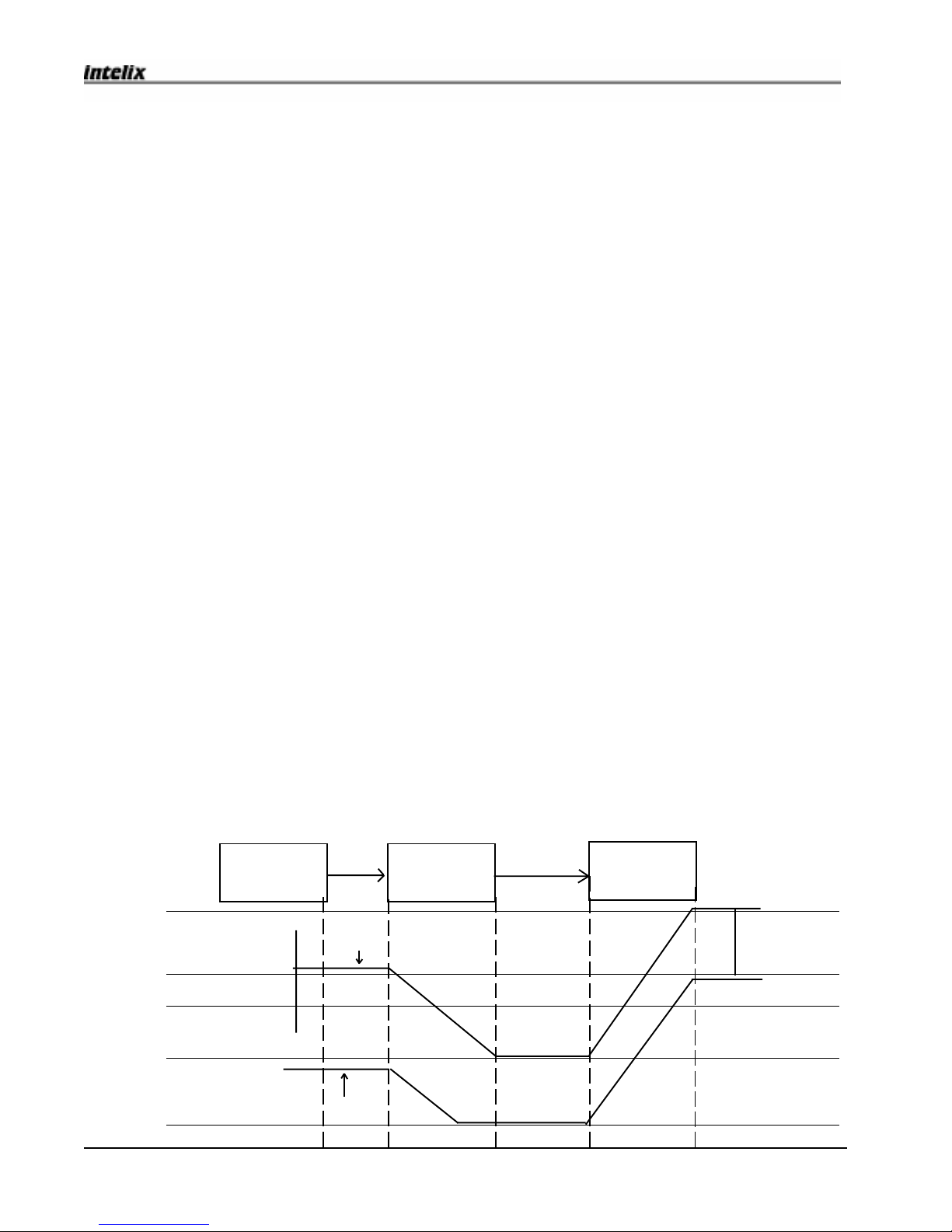
Fig. 12. Poor Signal Balancing. The drawing below shows the signal-to noise performance
when the user attenuates a +4dB signal by 50 dB through the Matrix. This scenario commonly
occurs when the user sets the Mini-Mixer controls at or below the nominal mid-point in an effort to
have maximum adjustment range. However, since the control is attenuation only, the nominal mid-
point is actually 50dB of attenuation. This setting results in the relatively poor signal-to noise ratio
seen here.
-90dB
-50 dB
-20 dB
0 dB
+40 dB
Signal Curve
Noise Curve
SN = 40 dB
Amplifier
Audio
Source Matrix
Mixer
SN = 65 dB
13
Psychologist Mixer User Manual
Psychologist Mixer User Manual
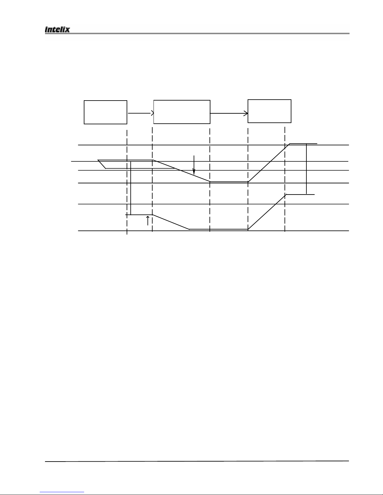
Fig. 13. Correct Signal Balancing. This drawing shows the result of correctly following the system
balancing procedure detailed above. The input signal is in the range of +4dB to +26 dB. With the
Matrix attenuation controls set to -12dB the input signal is attenuated to -8dB. The resulting signal-
to-noise ratio is improved to more than 80dB. +20 dB or more input signal would give better than
100 dB signal-to-noise ration.
+40 dB
0 dB
-20 dB
-50 dB
-90dB
+20dB
Signal Curve
Noise Curve
SN = 80 dB
Input range: +4dB-+26dB
Amplifier
Audio
Source Matrix
Mixer
SN = 90 dB
14 Psychologist Mixer User Manual
Psychologist Mixer User Manual
Inputsand Outputs
Each input and output channel uses a triplet Phoenix connector. For details on connecting inputs and
outputs, see page 21-23.
Inputs can be any line level source, such as musical instruments, microphones (preamplified to line
level), tape players, CD players, etc. Input connections are made to the blocks on the left of the
Matrix unit. The input plugs must be connected in ascending numerical order, from left to right, as
printed on the Matrix.
Outputsarewiredtomonitoramplifiers(headphone, floor wedge etc.) Outputconnectionsare made to the
blockson therighthandsideoftheMatrix unit.Theoutputplugsmustbeconnected inascendingnumerical
order,fromlefttoright,asprinted on the Matrix.
Each output is associated with a single Mini-Mixer. For example, the Mini-Mixer at address 03 may
control a pair of headphones connected to output number 3. The Mini-Mixer at address 10 may
control a monitor speaker connected to output 10. Stereo (2 output) Mini-Mixers use two consecu-
tive matrix outputs. (see Mini-Mixer location selector on page 18 for more information on stereo
pairing).
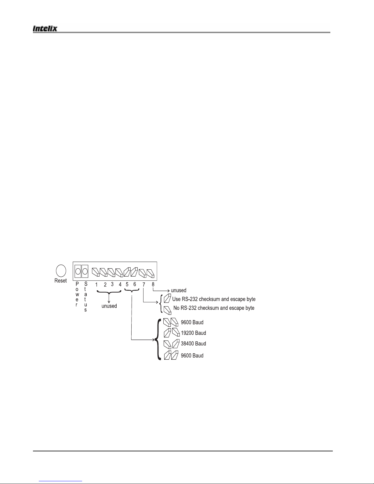
DIP Switch Settings
The DIP switches are the set of eight small toggle switches next to the Reset LED on the rear panel.
These switches define the mode of the central processor of the matrix system. They are set at the
factory and generally should not be adjusted. (Normally all switches are down.)
Baud Rate
DIP switches 5 and 6 control the baud rate between the RS232 control port and an external control-
ler. Note that this does not control the rate of communication between the matrix and the Psycholo-
gist remotes.
Checksum
DIP switch number 7 controls the activity of the checksum and escape byte function in RS232
communication. If the switch is in the up position, escape and checksum are used. If the switch is
down escape byte and checksum are not used. Intelix recommends using escape byte and checksum
inapplications whereRS232communicationmaybehindereddue tocablelength(amaximumof50 feet)
orlack of shielding fromexternalelectronicnoise.Escapebyteandchecksum should be turnedoff(switch
15
Psychologist Mixer User Manual
Psychologist Mixer User Manual
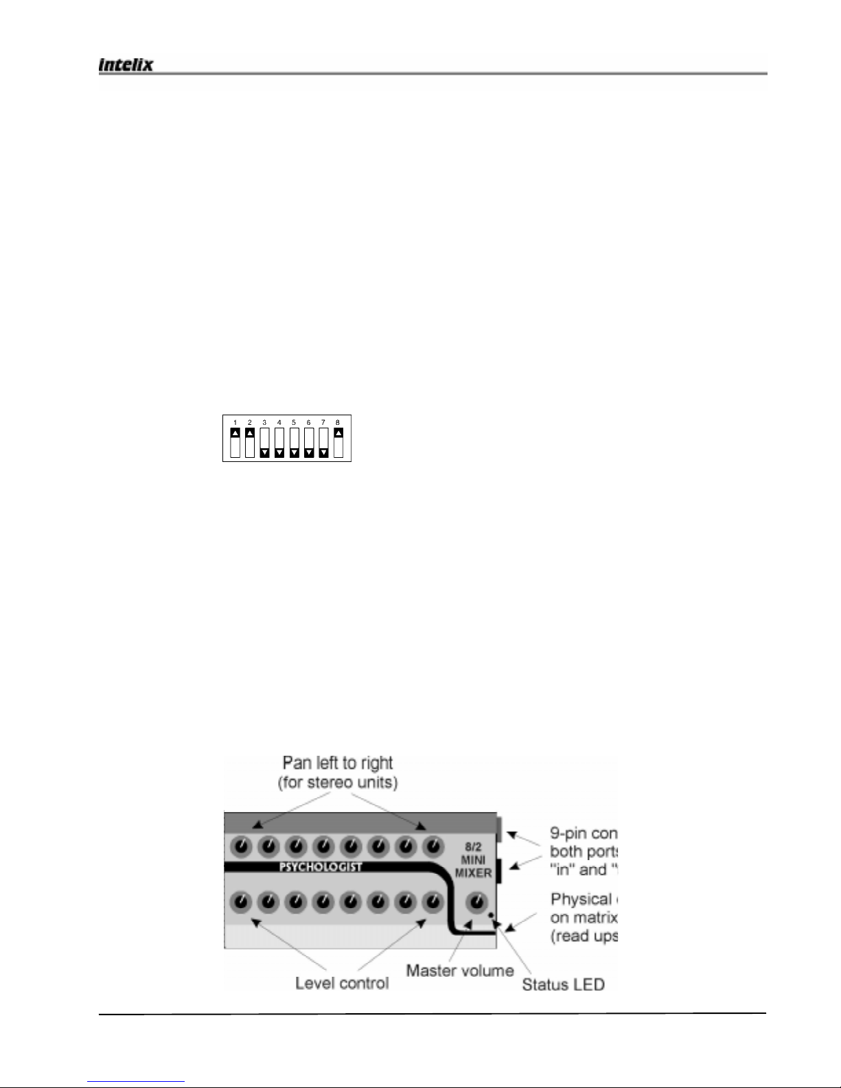
Mini-Mixer Remote Controllers
The Mini-Mixer remote controllers allow you to adjust the volume of each input channel
independently of any other output channel. Each Mini-Mixer has independent controls for each input
channel, plus a master volume control that affects all the channels. The status LED near the master
volume control indicates that the unit is on. (See Status LED on page 17 for more information.) A
typical Psychologist Mini-Mixer is shown below.
down)ininstallationswhichincludeapermanentRS232controllersuchasAMX,CrestronorcustomPC
program.
Unused switches
Switches 1,2,3,4 and 8 are unused except as noted in “Reset the matrix mixer memory” above.
Reset the Matrix Mixer memory.
Resetting the Matrix Mixer memory will cause the Matrix Mixer to look for and re-establish commu-
nications with all of the Mini-Mixers. This solves most system problems. To reset the memory,
locate the DIP switch on the rear panel of the Matrix Mixer and note the position of the switches. Set
switches 1, 2 and 8 to up, all others down, as shown in the illustration below. This clears the
memory. Then return the switches to their original positions.
Note: After changing any DIP switches, you must resest the matrix by pressing the reset button on
the rear panel. Changes will not take place unless you reset the matrix.
16 Psychologist Mixer User Manual
Psychologist Mixer User Manual
You can use several different styles of Mini-Mixers with the Psychologist system. Mini-Mixers
have either rotary or slider potentiometer controls (“pots”), with 8, 16 or 32 input channels in mon-
aural or stereo output. The different styles of Mini-Mixers, and the configurations that can result
from their combined use, are described below.
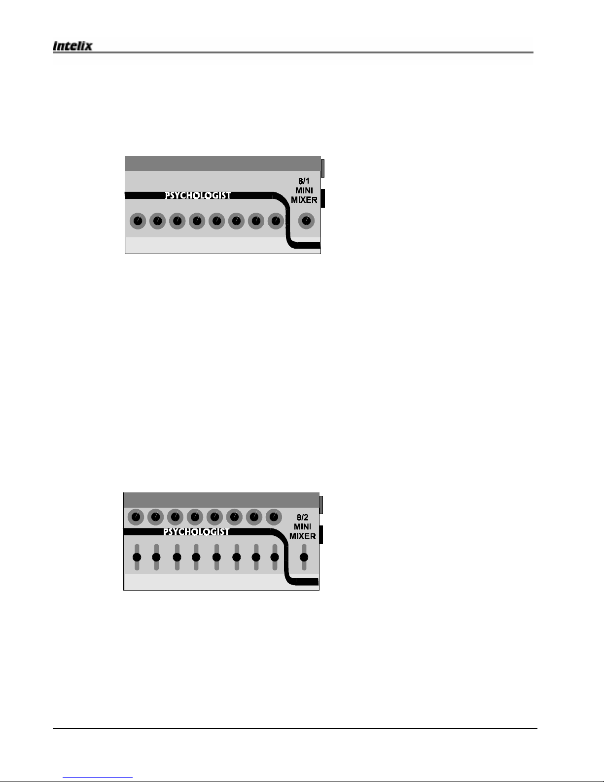
8/1 Mini-Mixer
8/1 Mini-Mixer with rotary potentiometers
The 8/1 Mini-Mixer is for use with up to eight monaural input channels. The 8 individual input
channel potentiometers control each of the inputs independently. It controls the mix to one monaural
output.
16/1 Mini-Mixer
The 16/1 Mini-Mixer can provide up to 16 monaural matrix input channels. The 16 individual
input channel potentiometers control each of the inputs independently to a single monaural output.
The 8/2 Mini-Mixer controls eight input channels for stereo output (two output channels). The 8
input channel pots on the lower row control the overall volume of a pair of matrix adjacent outputs
independently. The 8 pots on the upper row are the pan pots, and control the left/right balance of
each of the output pair independently.
8/2 Mini-Mixer
8/2 Mini-Mixer with slider potenti-
ometers.
32/1 Mini-Mixer
The 32/1 Mini Mixer provides up to 32 monaural input channels. The 32 individual input
channel potentiometers control each of the inputs independently. Two rows of 16 volume controls
adjust the mix of a single monaural output.
16/2Mini-Mixer
The16/2Mini-Mixercontrols16inputchannelsforstereooutput(twooutputchannels.) Each of the
sixteenlowercontrols(potsorsliders)controlthevolumeofapairof adjacent outputs independently.The
sixteenpotson the upper rowarepanpots and control theleft/rightbalanceof each output pairindepen-
dently.

17
Psychologist Mixer User Manual
Psychologist Mixer User Manual
Mini-Mixer Configuration
Status LED
An LED near the master knob (see page 15) indicates the status of the Mini-Mixer. The output
of the LED indicates the status of the Mini-Mixer.
Steady On The Mini-Mixer is powered up and communicating with the Matrix. This is the
normal condition.
Flashing A flashing LED indicates an abnormal status. The rate of flashing indicates the
problem.
• Slow (50% duty cycle) - The Mini-Mixer is powered on but has lost communication with the
Matrix.
• Repeating single flash (every 2 seconds) - The Mini-Mixer is powered on but has not estab-
lished communication with the Matrix.
• Repeating double flash (every 2 seconds) - The Mini-Mixer has been commanded to go to
set-up mode by the Matrix Mixer. This state is normally active for a short duration when new
remotes are plugged into the system and then changes to the normal, steady on condition.
• Fast flash (50% duty cycle) - The Mini-Mixer has conflicting output address assignments.
Initial conflict may disappear as the system continues its initialization procedure. This could be
caused by two Mini-Mixers having the same assignment, if stereo assignments overlap, or if assign-
ments are outside the range of the Matrix Mixer (including 00). To correct, change output selectors
of one of the two remotes with overlapping assignments.
Steady Off The unit doesn’t have power. Check the power supply. However, if the LED
never blinks following powering, there is either no power to the remote, or a fault in its electronics.
For troubleshooting help, see Troubleshooting Tips on page 27.

18 Psychologist Mixer User Manual
Psychologist Mixer User Manual
Mini-Mixer Power
All remote controls are powered by an external power supply, either the supplied transformer, or
another equivalent supply. The supplied Intelix PPS-12 contains a 2 amp transformer and supplies
power to multiple remote controls in a typical system.
Large systems may require more than one PPS-12. The PPS-12 supplies can be connected into the
system in any order. If you use a long cable between the Matrix Mixer and the Mini-Mixers, locate
the PPS-12 near the Mini-Mixers, not near the Matrix Mixer. If your system requires two power
supplies, put one at each end of the Mini-Mixer chain. For systems with more than two power
supplies, distribute the power supplies equally between the Mini-Mixers. If you use AC power, you
cannot parallel them! Only DC power supplies can be paralleled.
You can create a backup power supply by connecting an additional unit in parallel with the main
power supply. The supply with the lower input voltage will act as a backup.
Refer to the following listing for exact power specifications of any external power supply.
epyTetomeRderiuqeRtnerruC rebmunmumixaM
21-SPPrep
ylppusrewop
1/8Am2623
2/8Am21161
1/61Am21161
2/61Am2618
1/23Am2618
Mini-Mixer location selector
Each Psychologist system ships with Mini-Mixers configured to control an output on the Matrix.
Follow the instructions below to add additional Mini-Mixers or alter the system configuration.
The two rotary decimal switches (see page 26) within the Mini-Mixer determine which physical
output location (and I/O channel) the Matrix Mixer associates with that Mini-Mixer. Monaural Mini-
Mixers take one output location on the Matrix Mixer, and stereo Mini-Mixers require two adjacent
output locations. You can view the assignment of each Mini-Mixer by looking at the small numbers
inside the holes on the side of the unit near the cable connectors. Two small holes in the bottom of
the Mini-Mixer unit allow you to change the assignment switch settings.
For information on adding or reconfiguring Mini-Mixers with you system, see Adding Mini-Mixers
on page 26.
19
Psychologist Mixer User Manual
Psychologist Mixer User Manual
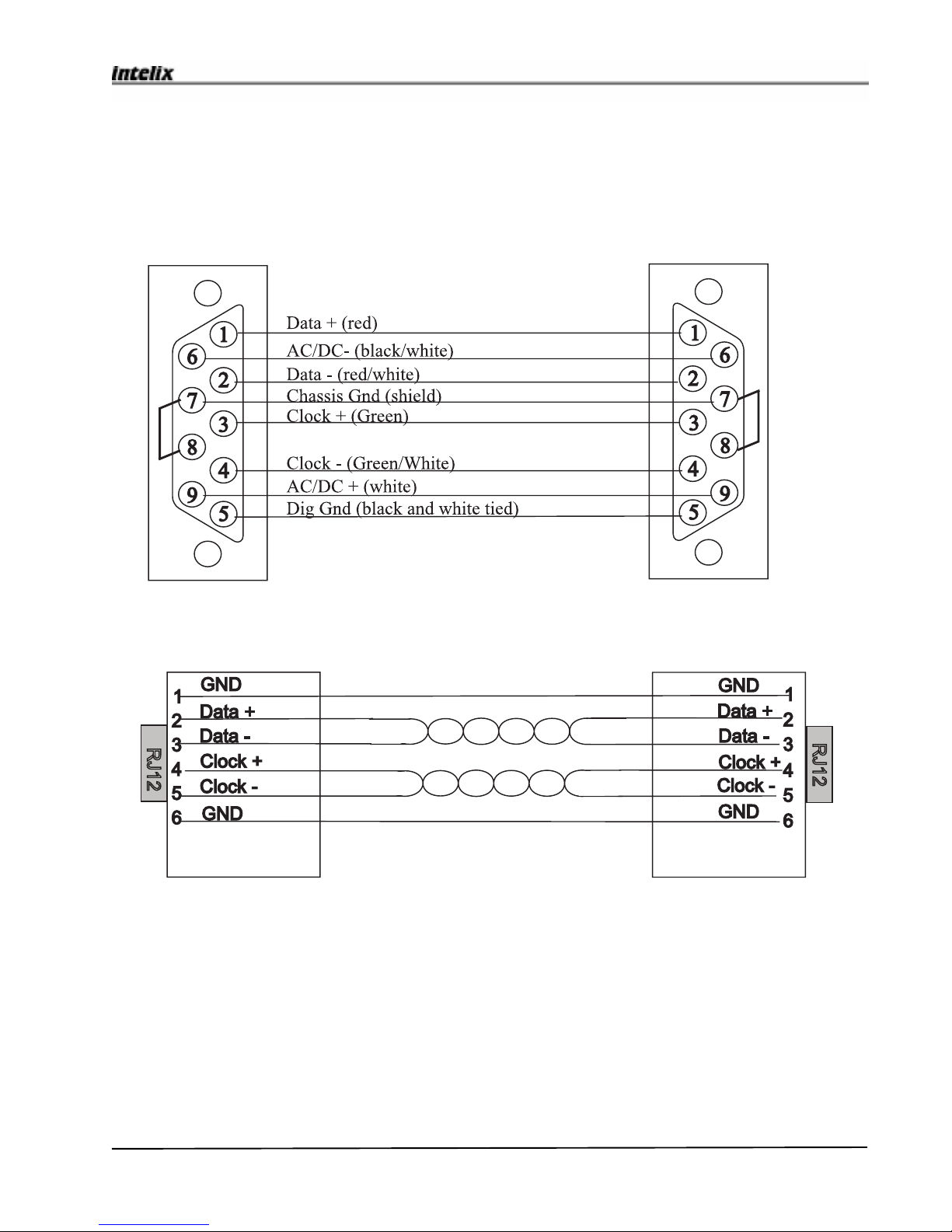
Power is fed to all Mini-Mixers via two pins on each 9-pin D connector. See below for a wiring
diagram. For DC power pin 6 is power ground and pin 9 is power plus (+). An external power supply
that provides the power connection may be either AC or DC. If DC, positive voltage should be
connected to pin 9, and ground connected to pin 6. The voltage should be 9 to 12 volts.
Note:The colorcode shownbelow isspecific forGepco6608,the cable recommended byIntelix.
ReO Bus Connections
The ReO bus that connects the minimixer remotes to the matrix mixer has the following pinout.

20 Psychologist Mixer User Manual
Psychologist Mixer User Manual
System Installation Reference
This section presents installation instructions for all systems. In this section you’ll find installation
details not found in the Quick Start section.
AC Power Connection
Intelix supplies an 18 Volt, 3.0 (or 1.5) Amp center-tapped transformer to power the Mixer. If you
use another AC supply, it must supply 18 volts and have at least a 21 VA rating for an 8 x 8 matrix
and 60 Volt-Amp rating for larger matrices. The following figure shows the the AC Power jack on
the rear panel.
DC Power connection
The mixer can also be connected to a DC power supply via the Molex-style DC power jack on the
rear panel. The DC supply can be used as the sole power source or as an on-line backup.
Note: If the DC supply is used as backup, it must meet the following voltage requirements:
√A regulated supply (for example, a battery) must be between 17 and 18 volts (voltages
greater than 18 will drain the DC supply; using less than 17 volts will reduce the dynamic range of
the mixer).
√An unregulated DC supply must be between 17 and 18 volts. If the supply is less than 17
volts, a hum may be audible at the outputs.
The current supplied mustbe at least 1.5 A for an 8 x 8 matrix and 3 A for larger matrices. The
wire configuration and voltage requirements are as shown in the right-hand figure below.
Rear Panel View
Table of contents
Other Intelix Music Mixer manuals


