SoundTracs Solo Live User manual
\i ?{
st
[;*
qs[
@
ENE
H
il
[fi
ffi
@
h@
ffi
k4
w
w
kq
bs
bt€'
h#
gOUNDTRAGSH
SOLO
''LIVE"
Mixing
Gonsole
Operator's
Manual
/
t
/
I
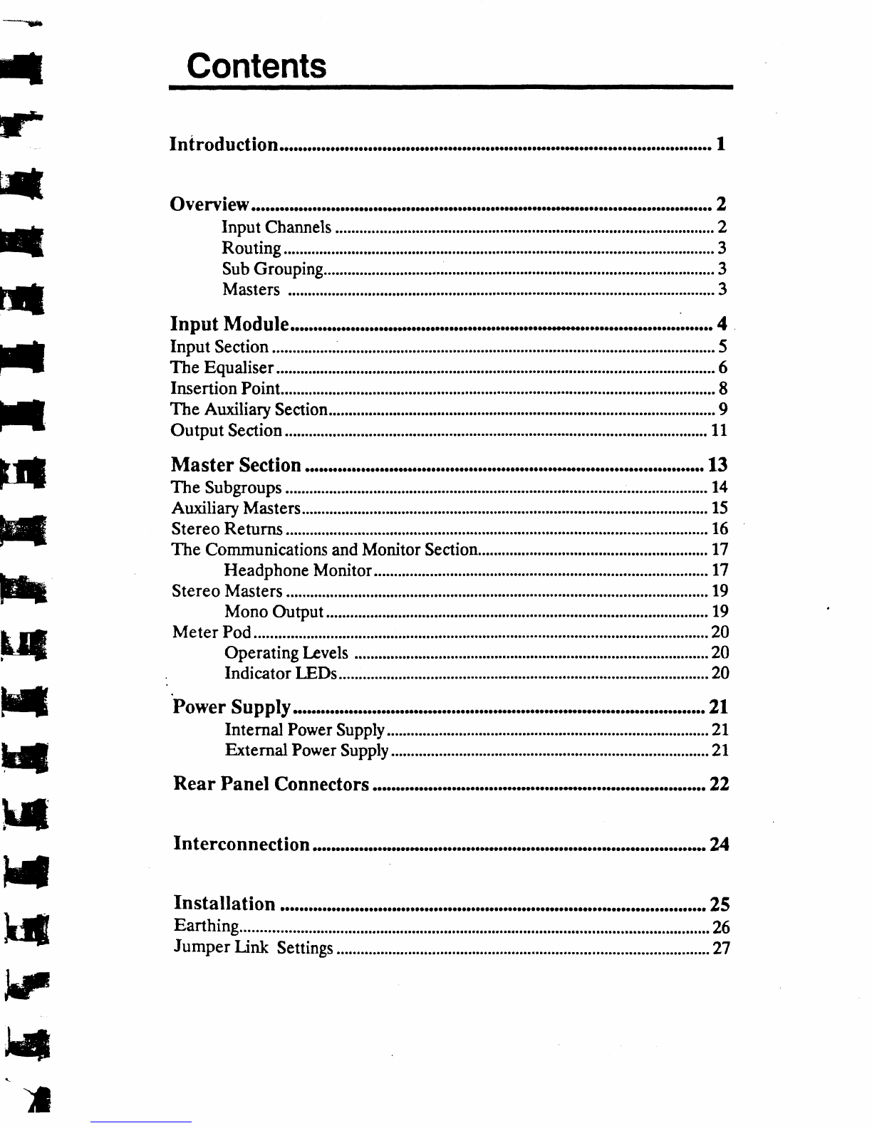
Contents
Introduction
Overview
Input Channels........'..............r........o..o.o.'.......o......o..o...r......r.......o'................2
ROUting....o.....r...'............o.........r...................r.r..........................o......r.............
3
SubGrouping.................'......r...'...r..................'o......o.....................................3
Masters ...........3
Input
Module
Input SeCtiOn.................o...o.......................D.....o...........'.....D r
r....
.... 5
..........6
The Equalisgr......................................o...........o................
Insertion Point.....r.........r..............o..........o...............
.........r...............e..,....,...8
Thg Auxiliary Sgction.r.....................r...o...........o.........o..r.,......,..................................9
Output SgCtion
..........o........r......................r................r...o...............o.........................11
Master Section.....................o...... ..........13
Headphong
Monitor............o........................o...,.. .........t7
Power
Supply............................o..... .21
Rear Panel Connectors.....o,......oo.o. ..22
Interconnection
Installation .o..........,25
Earthing..........................t....................................................................i..rr.r............r..26
JumperUnk Settings
.................................-...................................rt...r........
.........2'l
u
lntroduction
h||
hF
F{
Ff
HI
HI
I't
hil
[4
H*
h[
IJil
t;
t*
14
l{
t-r
II\
IJ
The
Soundtracs
SOLOisaseriesofthrec
conrcles"
with16,71and32inputs
respectively.
Theconsoles
have
four subgroups
in additionto stcreoand
monomaster
outputs.The
console
is
particularly
suitable
forPA and
stereo
record
i
nB
applications.
An internalpowersupplyisprovidedon all consoles
exceptthe 32input
model.Thishas
ancxtcrnal
19"rack
mountingsupply.
Soundtrecr SOIrt
Overview
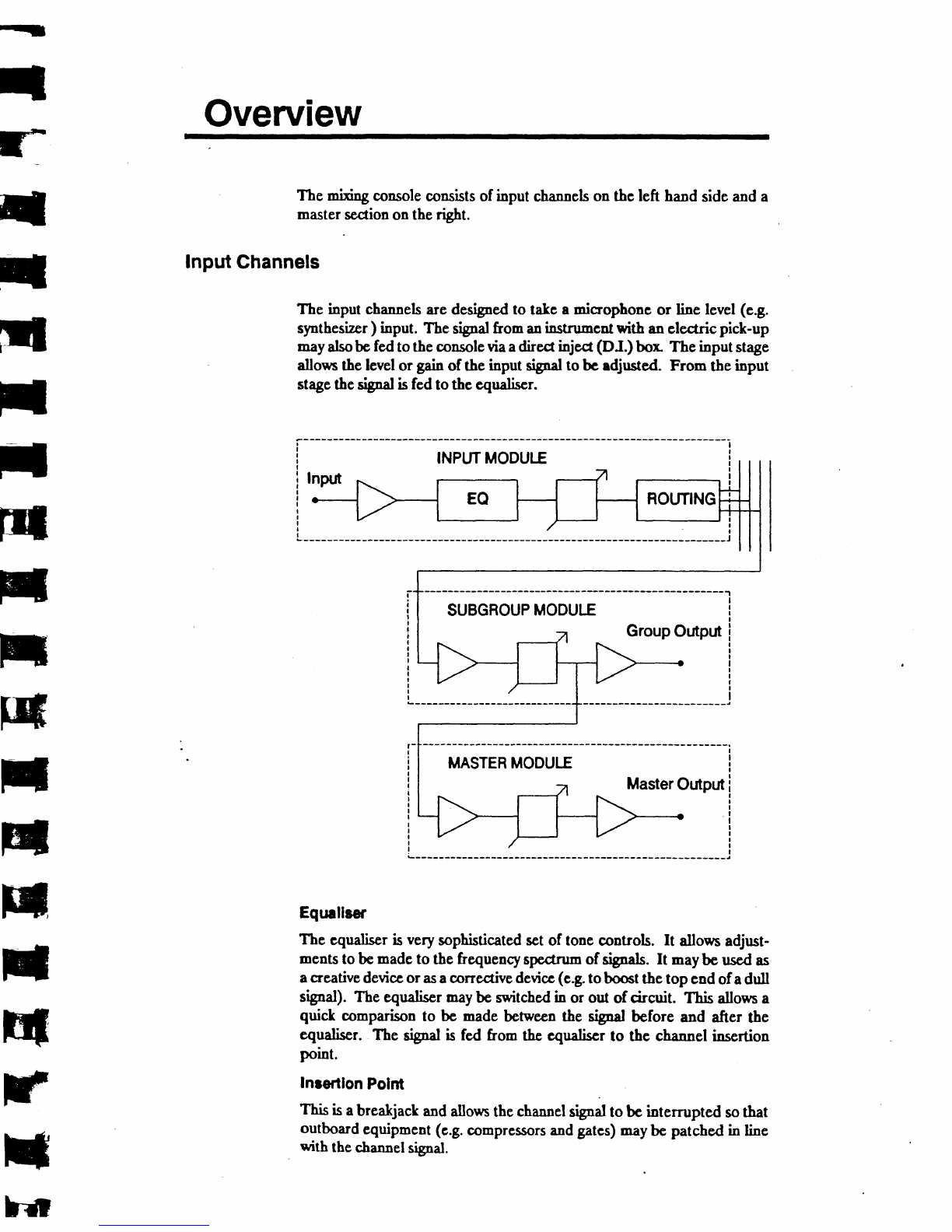
Themixing
console
consistsofinputchannels
onthcleft handsideanda
master
section
ontherigbt.
Input
Ghannels
Thc inputchannsl5aredesigned
to talc amicrophonc
or line level(e.g.
synthesizcr
) input. Thesignal
froman
instrumcnt
with anelectricpick-up
may
alsobe
fed
totheconsoleviaadirect
ioject
(DJ.) bor Theinputst4ge
allowsthelevelor gainof theinput *;gn'l tobc adjusted. From theinput
stage
thcsigfd isfcdtothcequdiscr.
INPI.TTMODULE
MASTEBMODULE Master
Outpnt
Eqtnllrer
The cqualiserisvery
sophisticatedset
of tonecontrols. It allows
adjust-
ments
tobcmadc
tothefrequency
spedrum
6f signels.
It maybeusedas
acreative
devicc
oras
acorrectivedevicc
(c.g.
toboct tbetopend
ofadull
srgRal).1be equalisermay
bc switched
in or out of circuit. This allowsa
quick comparison
to bc madebchpecn
the sigealbcfore and after the
equaliscr. The tigld is fcd from thc e4udiscr to tbe channelinsertion
point.
Inrertlon Polnt
Thisisabreakjack
andallows
the
cha'nelsignal
tobeintemrptedso
that
outboard
equipment
(c.g.
oompressorsandgatcs)
may
bc patched
in line
withthe
6fennsl
srgal.
SUBGROUP
MODULE Group
Outpnt

Aurilhry Sendr
Theauxiliary
scnds
dlow cfrra mixes
to bc madchom theinput channel
srgnals.These
aruiliarymixesmaybe fed to outboardeffectsunits (e.g.
reverberators)or usedas monitor mixesto fccd monitor wedges
and
sidefills.
Thesignal
fromthe
channcl
totheauxiliaries
maybe
taken
before
orafter
(PREor POST)
thechannel
fader. For scnds
to outboard
effects
u"its a
post-faderauxiliarysend
innormallyuscd:this
kecps
theamount
of signal
sentto theoutboard
proccssor
constant
rclativeto the level
of the main
slpal. Foldback
mixes
are
bcst
created
usinga
prc-fader
aux
scnd,keeping
controlof thelcvelsof signal
sent
to thefoldbacknix andthenain mix
separate.
Routing $ii*#*l'[+HhH"r:*;#fffi
%"j'ffi
thesignal
inthesterco
i-age (i.c.
bctween
leftand
right).
SubGrouplng
Stgnals
fromtheinputchannels
maybe
routed
tothe
foursubgroupsaswell
as
tothestereo
rnasters.
Sigals routedto thesubgroupsappear
atgroup
outputs
onthere,ar
panel buttbesubgroup
signals
may
alsoberoutedto
themasters.Thisisaccomplished
usingtheMIX and
PAI{contrpls
onthe
subgroup.Subgrouprng
in thiss,xy
can
facilitateopcration
considerably.
For exampledl thednrmandpercussion
inputchannelscould
berouted
to groups
1and2. Subgroups
1 and?couldthen
berouted
to thc stereo
masters.Thus
the
level
ofallthedrumscan
becontrolledusing
justgroup
faders
l and
2.
Masters
Thestereo
masters
areuscdasthemain
outputs
tothePA sptem or tape
recorder.Breakjact
inscrtion
points
areprovid"d.oq
thestereomasters.
For PA wort these
can
oftenbensedto good
efrectbypatching
asterco
graphic
equaliser
intocircuit.This
canbe
used
toadjust
theoutput
signal's
frequency
spectrumto compensate
for theacoustics
of theroomor hall.
For both PA andrecordi.g a stereo
compressor
qanoften be usefully
cmploycdontheoutputor patcbed
in to theinscrtionpoints
ts limil any
cxccssive
pcats
and
transientsinthcprogramme
material.
I

Theinput
moduleq
ufiich may
bc 16,?A
or3zinnumber,
arelocated
atthe
lefthand
side
ofthe
console.
These
modules
takc
amicrophone
orlinelevel
input slgnal adjrxt its' gein, allow it to bc proccsscd
by the channsl
equaliser,
fedto erCernal
cffectsfor further
treatment,
andthenroutedto
goup andmaster
outputs.
In{ft
rt
|I,*
NT
t
ril
rl
t
rut
t
Fil
mil
t
ilf
*
t
il
3
t
rE{

lnput
Section
The
inputsection
comprisesbalanced
microphone
andlineinputs.
The
line
iaputisaccessedviaastereo
jact socket
onthercarpanel
oftheconsole.
Themicrophone
inputisaccesscd
byathr*-ptq female)(LR connector
onthe
rearpanel.
Forinformation
onconncdionsrcfertothe'RearPanel
Conneclors"cbapter.
MIC / LINE
This switch is usedto setect
between
the
microphoneand
lineinputs.When
theswitch
is
in theraisedpositionthc MlCrophone rif.l it
sclectcd. When thc switch is depressed
the
LINE signal
isscleaed.
GAIN
Thiscontrolisnscd
totrim thegainof theinput
stagein order that the input sigpalmay be
matchedto the opcrating level of the mixer
cbannel Careful matchingof the input gain
allowsthe optimumsignal
to noiseratio to be achicved. Thc input gain
should
be adjusted
bysctting
thecha"nel
fader
to S" andadjusting
the
GAIN controluntil thesbal is at a convcnicnt
levelfor the mi:r,
or by
PFLi"g thesignal
and
adjustingthe
GAIN controluntilthesrfal averages
OdBonthe
meter.
When
the
MIC input
isscleaedthe
input
gain
is
adjustable
between
+ 10dB
and +60dB. Whenthe LINE input is selected
the gain is adjustable
between
-20d8and +30dB
?4
Ttrg
UIC -trI
GADI
The
Equaliser
.tl
il
['
Fil
n
nf
Fil
f,t
iq
il
FT
F,*
FS
Ft
q
rr
ry
x"
}n
---.5
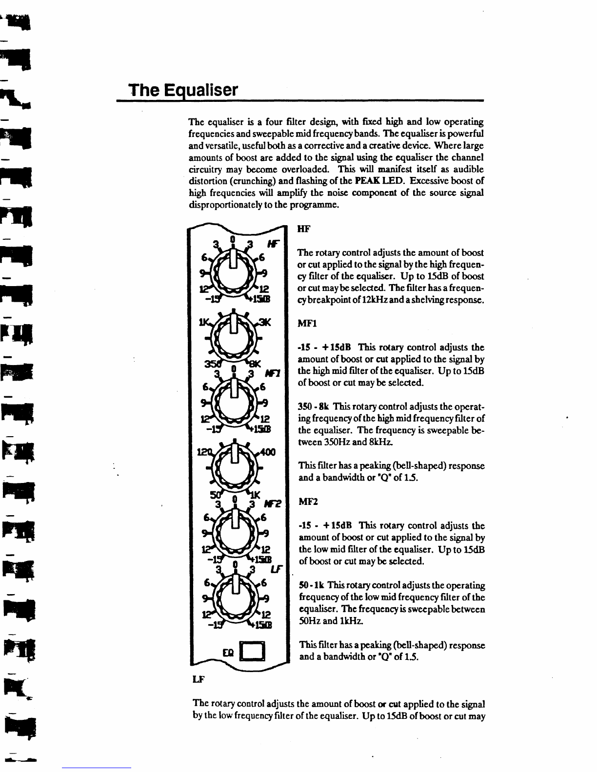
The equliser is a four filter design,
with fixcd high 41d low operating
frequencies
and
sweepable
midfrequencybands.
The
cqualiser
ispowerful
and
versatile,
useful
both
as
acorrective
andacrcatirredevicc.Where
large
amounts
of boost
areaddedto thesifal using
thccqualiser
thechannel
circuitrymaybecome
overloaded. This will rnanifest
itself asaudible
distortion
(crunching)
6d fl35hingofthePEAKIJD. Excessiveboost
of
highfrequencies
*ill *pltfy the noisccomponent
of the souroe
srsal
disproportionately
totbeprogrem
me.
-*El
LF
IIF
Therotary
control
adjuststheamountofboost
orcutappliedtothesiglalbythe
high
hequen-
cyfilter of theequaliscr. Up to 15dBof booat
orcut
maybe
seleaed The
filterhas
afrequen-
cybreakpointofl2kllz and
ashelving
responsc.
lrFl
.15 - + lSdB This rotarycontrol adjuststhe
amount
ofboostor cutappliedto thesignat
by
the
higbmidfilteroftheequaliser.Up to 15dB
ofboost
orcutmay
beselected.
350
-tk Thisrotary
controladjuststhe
operat-
ingfrequencyofthe
hrgh
-id frequency
filterof
theequaliscr.
Thefrcqucncy
issweepable
be-
tween350H2
and8kHz
ThisFrlter
has
a
peakiry
@ell-shaped)
response
and
a
bandwidth
or'Q" of15.
MEI
-15- + lSdB Thisrotary control adjusts
the
amount
ofboostor cutapplied
tothesrgnal
by
thelowmidfilteroftbeequalicer.
Up to 15dB
ofboostorcutmaybc
sclected.
$ -lk Thisrotary
control
adjuststheopcrating
frequency
ofthelowmidfrequencyfrlterofthe
cqualiser.Thcfrequencyis
swecpable
betwecn
50Hz
andlkllz
This
filterhas
a
peelring
(bcll-shaped)
rcsponse
and
a
bandwidth
or'Q" of15.
Theruary control
adjuststheemount
ofboost
d cutapplied
tothesrsal
bythelowfrequency
filteroftheeQualisgl.
Up to15dB
ofboost
orcutmay

beselected.
Thefilter has
afrequencybreakpoint
of 80Hzandashelving
resPonse.
EQ
This is usodto switchthe equaliser
in or out of the chat"tel signalpath.
Whenthe switchis in the raiscdpositionthe cqueliscris switched
out of
the channel
signdpath. Whenthe ss,itch
is dcpresscdthe cqualiseris
switched
in tocircuit.

lnsertion
Point
ru
t
r
It
nt
nt
t
t
ilt
nl
t
h*
T
4
4
{
h*
t
*
ril
The inscrtion
pointallows
efrernaleffccts
units
tobepatched
in linewith
the channelsignal
path. Theinsertion
pointisacccssed
by a stereo
jack
socket
markedINJECTlocatedon
therear
pancl Thisis
wiredringsend,
tip return. Thesend
isnormalled
tothereturn:thatisto saythereturnis
normally
connectedto thereturn,sothatthere
isnobreakin thechanttel
sigpal
path.
Whenaplugis
inserted
intothesockctthe
normallingcon$ec-
tions
are
broken,breakingthe
chennel
sisnal
path
andallowing
anexternal
effects
unittobe
patched
intocircuit.
Several
t)"es of signdprooessormay
usefully
bc connected
to thechannel
insertionpoint:
Firstly dyna-ics controtdeviccs.Thescar's
rrni15
suchasoompressorE
de-essers
and
noisc
gates.
These
gcnerallyworkmost
effectively
ea3
5ingls
sigpal
atatime.A compressor
reducesthe
dynamic
range
ofa
signa[either
to eliminate
transient
peakswhichBay causeowrloadi.g, or to make
a
slsal tighlsl and
more
"punch/. A noise
gate
attenuates
or reduces
the
gainwhen
thesignal
&opobelowapreset
level,
to renderanynoiseless
obtnrsivenhentherearegaps
in thesignal.A noisc
gatemayalsob€used
creatively,e.g.
togate
the
signalfromareverberator.
Reverberators
are
normallyconnected
viatheauxiliary
sends,but where
a
specificreverberationefrect
isrequiredon
one
channelonlyit maybemore
convenient
to patchit into theinsertion
point, andusethe weVdrymix
controlonthe
reverberatoritselftocontrolthe
relative
levels
oftbetreated
and untreatedsignals.Operati"gin thiswayalsomeans
rhat an entire
aruiliarybusisnot
tiedup
feeding
a
processor
which
is
usedonone
channel
only. Othercffecti (c.g.
d;gtal delaysandchonx units)may
beusedin a
similar
rnanner.
Thistechnique
isnothowever
suitable
for usewitheffects
unitsufiichdonothaveatreated/untreatedslglal mixcontrol.
The
Auxilia Section
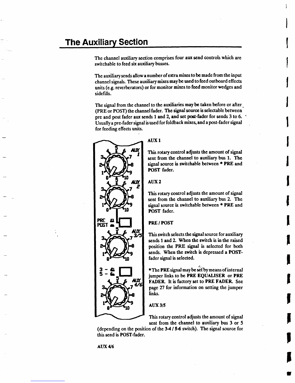
Thechannel
aruiliary
section
comprises
four auxscnd
controls
whicharc
switchable
tofeedsixauxiliary
busses.
Theauxiliaryscnds
allowa
nuorberofefrramixe.stobc
madefromtheinput
channel
sgals. These
arxiliary
nixes
maybcus€dtofeed
outboard
effects
units
(e.g.
reverberators)
orformonitor
mixesto fecdmonitorwedges
and
sidefills.
Thesignal
fromthechannel
tothcauxiliaries
maybetalcn before
or after.
(PREorPoST)thechannet
fader.
6e signal
sourcc
isselectable
behveen
preandpostfader
aux
scnds
1and
4 andset
post-fader
for sends
3to 6.
Usually
a
pre-fader
strnal
isused
forfoldback
mixeg
and
a
post-fader
signal
for feedingcffects
units.
ATIXI
Thisrotarycontrol adjuststheamount
of signal
sentfrom the channelto auxiliarybrs 1. The
sigal sour@
is switchable
bctween
r PREand
FOST fader.
ATIX2
This
rotarycontroladjruts
tbeamountof signal
sent
from the chan"cl to aruiliarybrs 2. The
sipal sourcc
isswitchable
benveen'PRE and
FOSTfader.
PRE
/ FOST
''Ihis
switch
setects
the*bd souroe
forarxiliary
sends
I and2. Whenthc switchisin the raised
position the PRE sigBalis setectedfor both
sen&. Whenthe s;witch
isdepressed
a FOST-
fadersifd issclected.
r The
PRE
signal
maybe
,"tty -r"* ofinternal
ju-p"t linla to bePREEQUALISER or PRE
FADER-It isfactorysctto PRE
FADER- See
page
Tl for information on scningthejumper
links.
AIIX3/5
This
rotary
control
adjuststheamountofsignal
sentfrom thc channelto auxiliarybrs 3 or 5
(depcnding
ontheposition
of the34 I 54 switch).Thesignalsource
for
this
scnd
isFOST-fader.
ALIX
/V6
I
I
j
r

rry
This rotary control adjusts the amount sf signelscnt from the chattttel to
auifiary bus4or 6 (depesding on the position of the t4 I 54 switch). The
Elgal sourccfor this scnd isFOST-fader.
34t54
Thisswitch
isrsedtodetcrmine
thebtrs
dcstisations
for AIIX 3/5andAIIX
{6. Whentheswitchisin theraiscdposition
thc rotary control AIIX 3/5
fecds
toauxiliary
bus3,and
controlALIX
tV6
fccds
toaruiliarybus
4. When
theswitch
isdepressed
controlALIXyS fc€ds
auiliary bus5,andcontrol
ALIXtUj fecds
to auxiliarybus
6.
Out Section
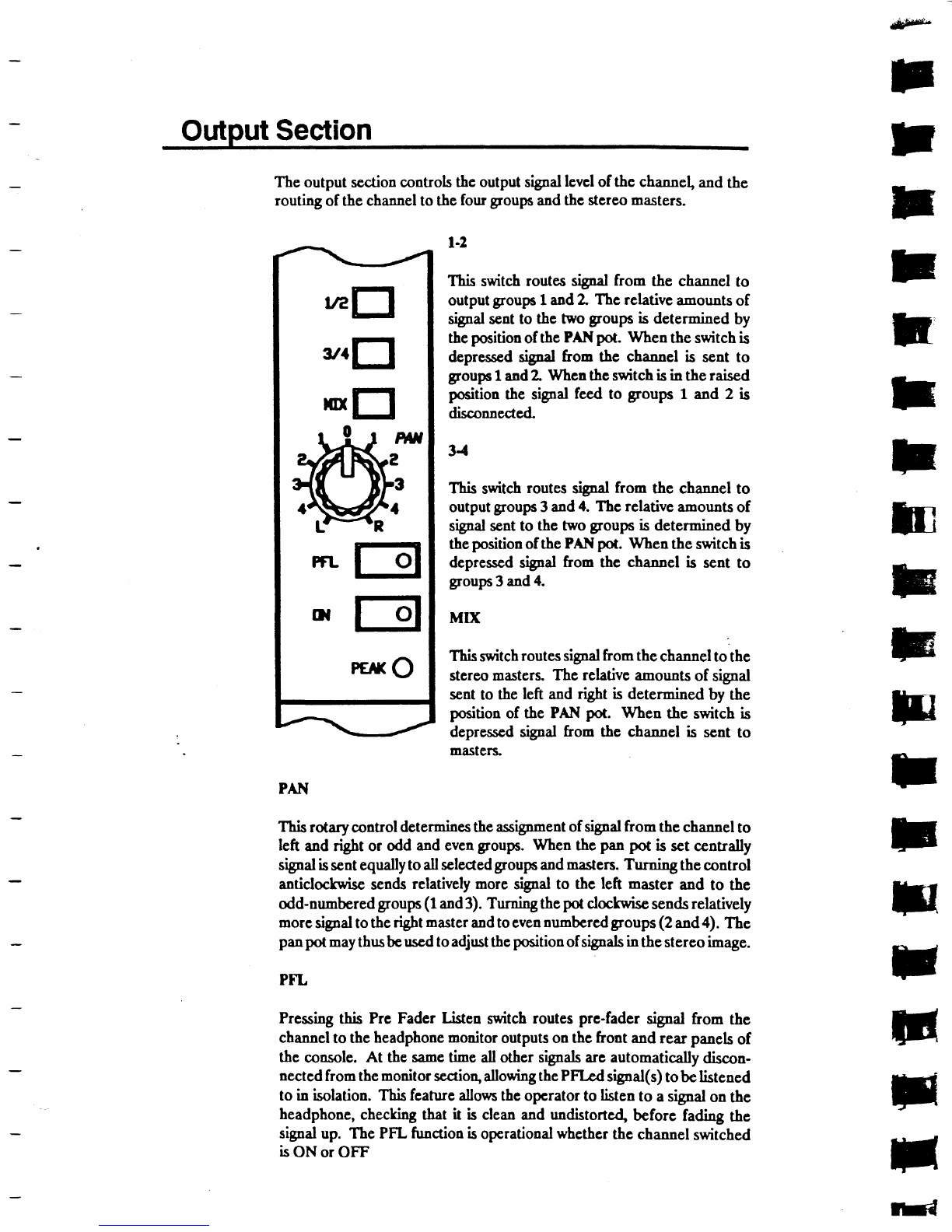
Theoutputscctioncontrols
thcoutputsigDal
levcl
of thc channelandthc
rsutingofthesfuannslto thcfourgroupe
and
thcstcreo
masters.
la
Ttis switch
routes
tignd from the channel
to
output
groups1andZ Thcrelative
amounts
of
srgnal
sent
to thc twogoup6 is determined
by
theposition
ofthcPAN
pot. Whentheswitchis
depresscdrignd from the channelis sent to
groups
1and2 Whcnthcswitchisin theraised
positionthe signalfeed to gfoups 1 and 2 is
disconnected
3-l
Ttis switch
routes
rifd from the channelto
output
goups3and
4. Tbcrelative
amounts
of
srgpalsentto thetwogfoupcis determined
by
theposition
ofthePAN
pot. Whcntheswitchis
depresscdsignat
from thc channclis sent to
goups 3and
4.
MX
Ttis switch
routessignalfromthechannel
tothc
stcreo
masters.
Therelativc
emounts
of signal
sent
to theleft andrigbt is determined
by the
position
of the PANpot. When the switchis
depresscdsigpd from the channelis scnt to
masters.
PAT{
This
rotarycontrol
determines
the
assign-ent
ofsignal
fromthechannel
to
left andrigbt or odd andevcn
goups. Whenthc panpot is setcentrally
slgnal
is
sent
equdly
todl selected
groups
and
masen. Turningthe
control
anticlochryisc
sends
relativelymorc rignd to thc left masterand to thc
odd-numbcred
groups
(1
and
3).Turning
the
potclockwisc
sends
relatively
more
sigealtothe
right
master
andtocven
nu-bcred goups (2and
a). The
paDpot
maythusbe
uscdtoadjrstthe
positionof
signals
inthe
stereoi-"g".
PFL
Pressing
this Prc FaderLigen snitchroutes
pre-fadersipal from the
channel
totheheadphone
moaitor
outputsonthcfrontandrearpanels
of
theconsole.
At thesametirne
allothersgpalsarcautomatically
discon-
nected
fromthe
monitor
scction,allowing
the
PFIrd signal(s)
tobelistened
to in isolation.
This
fcature
allowstheopcrator
tolisten
to asignal
onthc
headphone,
checlringthat it is clean
andundistorted,
before ;x<ling
the
signal
up. ThePFLfunction
isoperational
whethcr
thc channel
switched
isON or OFF
{$$8*
F
r
r
E
fr'
F
F
ft
F
F
lE
:
F
E
F
E
F
F
H
U?EI
trt
trt
EI
t-91
PEx
o
311
l|Ix
PTL
TDI

r
T
T
t
t
f
t
t
l-
I
I
ON
Tbis
switch
is
usedtoturnthe
chnnnelonand
off. Wbcn
theswitch
isinths
raisedposition the channelis OFF. Whenthc switch is depressed
the
channelisON. Whenthechannel
is
turned
Oftr thcfeedstoallauxiliaries
(preor postfader),
andto thegoups and
mastersaremuted.
PEAK
This rcd LED (ltght enitting diode)ill'rminatc uftcn the channel
ap-
proaches
an
overload
situation.The
LED is
actirated
SdBbefore
tbconset
ofclipping
(distortion).Thcinput
GAIN
control
should
bcadjusted
sothat
theLED doesnotflashcxcept
onthehighestlercl, brief [ransisats. Using
excesqive
amounts
of booet
onthc chennel
eqrnliscrmaycause
distortion
onthe'ihannel if thishappcosturn thcioputGAIN control down.
FN)ER,
Thc channclfadcr is a lfi)mm travelaudiofadcr. It adjuststhe level of
sigDal
sent
from 1f,schannelto thegoupq sterco
m*sters
andpost-fader
auiliary scndr
To allowtheoptimumrange
ofcontrolthcfadcrshould
bc run closcto the
0positiononthescale.
TheinputGAINcontrol
shouldbc setto allowthis.
r
I
I
Master
Section
The master
seclionis sinrated
on the rigbt handsideof the consoleand
compriscs
thc foursubgroupgthc stcrcomasterg
thc stereo
returns,
the
auxiliarymasters
and
thcssmmrrnicstions
section-
-13-
SoundtnetSOLO
I
TThe
Subgroups
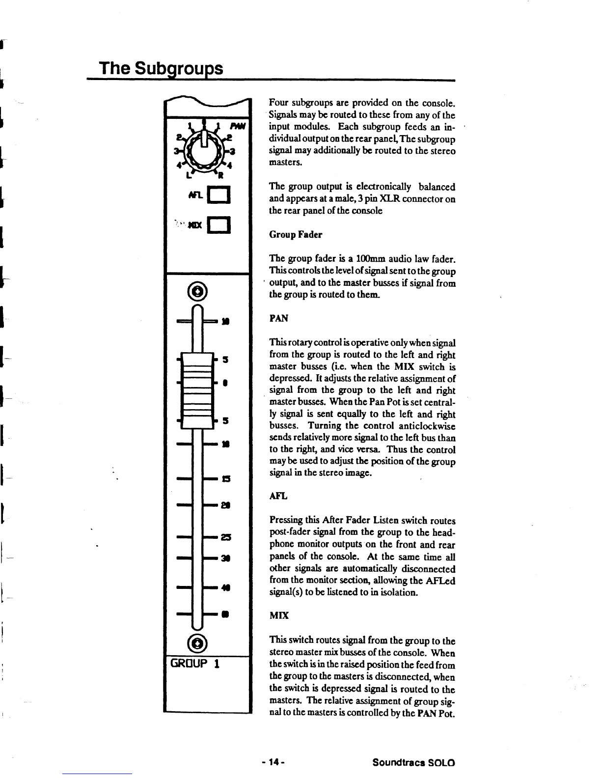
Four subgroups
areprovided
on the console.
Sipals may
bcrouted
tothese
from any
ofthe
input modules. Eachsubgroup
feeds
an in-
dividualoutput
onthc
rearpanel,The
subgroup
signal
may
additionally
bcrouted
to thcstcreo
masters.
The groupoutputis electrooically balanced
andappcars
at
a
maler
3pio}(LR connector
on
therear
panel
ofthcconsolc
GroupFader
Thegroupfader
isa 1ffimmaudiolawfader.
Thiscontrolsthelevel
ofsignal
sent
tothegFoup
' output and
tothcmaster
bussesif signal
from
the
group
isrouted
tothem-
PAI{
This
rotary
control
is
opcrativeonlywhen
signal
fromthegroup
isroutcdto the left andright
master
busses
(i.e.when the MIX switchis
depressed"
It adjuststhcrelative
assignment
of
signalfrom the group to the left and right
mrster
busses.
When
the
PanPot
is
setcentral-
ty stgoal
is sentequallyto the left and right
busses.Turning thc control anticlockwise
scnds
relatively
Eorcsrsal tothcleftbusthan
to thengft, andvicctrcrsL Thus the control
maybe
used
toadjusttbcposition
ofthe
group
signal
intbe
stereo
i-age.
AFL
Prcssing
thisAfter FadcrListenswitch
routes
post-fader
srgDalfromthc groupto thehead-
phone
monitor
outputs
on the front andrear
panels
of the consolc. At the sane time atl
other slgnalsare automatically
disconnected
fromthemonitorsection,
allowingthe AFI-ed
signal(s)tobe
listened
to in isolation.
MTT(
This
switchroutes
stgnal
fromthegroupto the
stereo
master
mixbusscs
ofthe
console.
When
theswitchisinthe
raiscdposition
thefeed
from
thc
group
tothcmasters
isdisconnected,
when
thcswitchisdcpressed
signal
isroutedto the
masters.
The
relative
assignment
ofgroupsig-
nal
tothcmasters
is
controlled
bythcpAh{
pot.
1-
I
1-
l-
I
l-
I
fLEI
r',,nr
trl
- t4- SoundtraceSOLO
Auxilia Masters
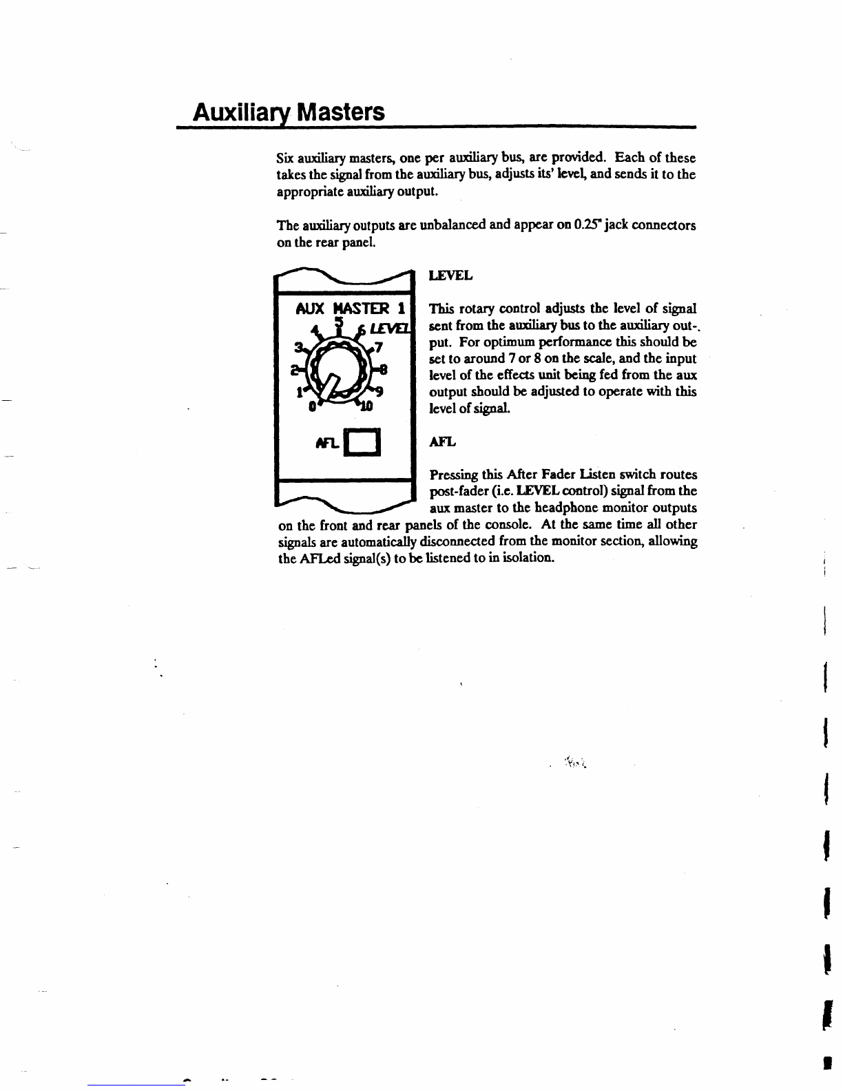
Sixarxiliary mastergoneper aruiliary bus,areprovided. Each of these
takes
ft6 signal
fromthearuiliary
bus,
adjr,rsts
its'lewl, andsendsit to the
appropriateauxiliary
output.
Theauxiliaryoutputs
are
unbalanced
and
appcar
on0.2yjackconnectors
onthe
rear
panel.
LEVEL
This rotary control adjuststhe level of signal
sentfrom the auxiliary
brs to the auxiliaryout-
put. For optimumpcrformanccthisshouldbe
set
to around
7or 8onthescale,andtheinput
levelof theeffects
unit bcingfed from the arx
outputshould
beadjustedto operate
with this
level
sf signal
ATL
Pressing
thisAfter FadcrListenswitch
routes
post-fader
(i.c.
LEVELcontrol)srgnal
from the
aux
master
to theheadphone
monitoroutputs
on the front andrear panelsof the console. At the sametime all other
sigals areautomatically
disconnected
from themonitor section,alowing
theAFLcd sigodG)
tobe
listenedtoin isolation.
"Tl-t. i
A|'D(]IASTER
tj-.f^
{q
fLEI
I
Stereo
Returns
T
T
f
+
f
+
+
f
T
tr
t
ryr
I
ry
I
H
il
ffi
H
il
F
f
*
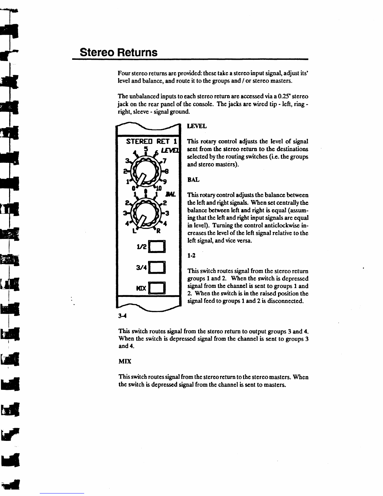
Fourstcreo
returns
are
provided:
thesc
take
astereo
inputsigal, adjustits'
leveland
balance,and
route
it tothe
groups
and
/ or stereo
masters.
Theunbalancedinputstoeacb
stereo
returnare
acccssed
viaa02f stereo
jack ontherearpanel
of theconsole.
The
jacls arcwiredtip - left,ri"g -
ngnt, slecve
- srgnal
ground.
LEVEL
This rotarycontrol edjuststhc levetof sifal
sentfrom tbc stereo
rcturn to the destinations
selected
bythcrouti'g switches
(i.e.
thegroups
and
sterco
mastsls).
BAL
Thisrotarycontroladjuststhebalancebehpeen
the
leftand
rigbt
rigrr
*. When
sct
centrally
the
balance
bct*rcn left andright iseqo"l (assn--
rngthattheleftand
rigbt input signals
areequal
in level). Turningthecontrol anticlochpiscin-
creasesthe
levelofthe
leftsignal
relative
tothe
leftsignal,
and
vicer€rsa.
ta
'fhisswitch
routes
signat
fromthestereoreturn
groups
I and
2. Whea
theswitchisdepressed
siglal fromthechannelissentto groups
1and
2 When
theswitch
isin theraiscdposition
the
srgpal
feed
togloups
1and
2isdisconnected.
Thisspilchroutessigpalfromthestercoreturnto outputgloups3and
4.
Whentbeswitch
isdcpresscdsgal fromthechannelis sentto groups
3
and
4.
Mtx
This
switch
routessigndfrom
the
stereo
rcturn
tothcstereo
masters.
Wben
theswitch
isdepresscdsignd fromthe
channel
isscnt
to masters.
STEREERET I
vaEl
',.El
mrEl
The
Communications
and
Monitor
Section
FTE
o
tl-fm
\
errutrl
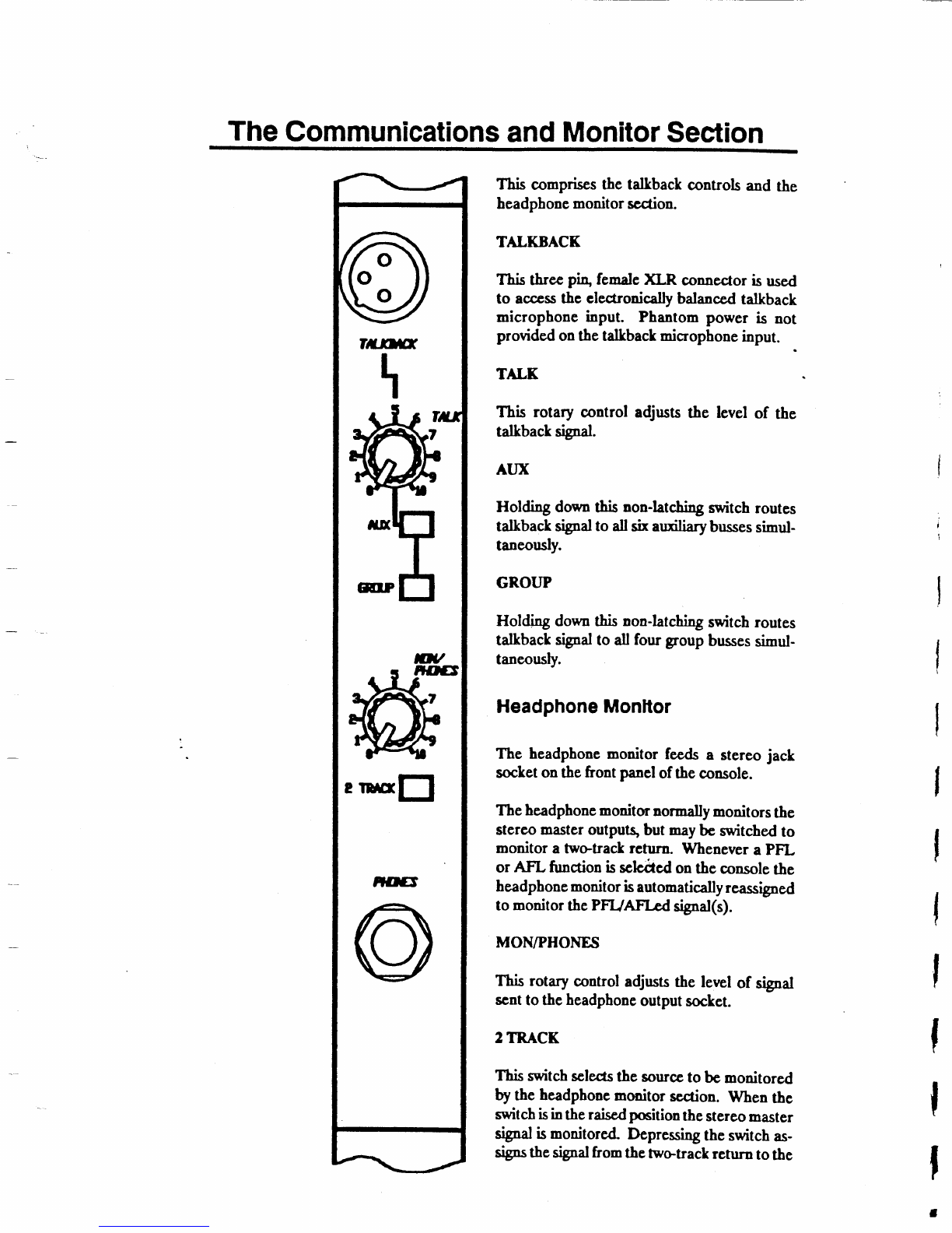
OThis comprises
the tdkback controls and the
headpbone
monitor
scdion.
TALKBACK
This threcpr4 femaleXLR connectoris used
to access
thc clectronicallybalanced
talkback
microphoneinput. Phantompower is not
provided
onthetalkbackmicrophone
input.
TALK
This rotary control adjrsts the level of the
tdkbact tipd.
AIIX
Holding downthisnon-latching
switch
routes
tdkbacksigBat
to allsh auiliarybusses
simul-
taneously.
GR.OTJP
Holdirg downthisnon-latching
switchroutes
talkbact sifal to dl four groupbusses
simul-
taneously.
Headphone
Monltor
The headphonemonitor fepdsa stereo
jack
sochet
onthefront paneloftheconsote.
Theheadphone
monitmnormally
monitors
the
stercomaster
outputg but may
bc switchedto
monitoratwo-trackrcturn. Whenever
aPFL
or AFL functionissctcAcdontheconsole
the
headpbonemonitor
isautomati*lly reassigned
to monitor
the
PFUAFI-edsigpalG).
MON/PHONES
This rotarycontroladjrststhe levelof signal
scnt
totheheadphonc
output
socket.
2TRACK
This switch
sclecsthe source
to bc monitored
b th. headphone
monitorscaion. Whenthc
switch
isinthe
raisedpcition the
stereo
master
signdismonitored Deprcssing
theswitch
as-
sigP.the
sigmal
from
the
two-track
returntothe
headphone
monitor. The two trackreturnioputis accessedviaa 02s
stereo
jact connector
ontherearpanel.This
iswircdtip -left sigDal,nng
- rigbtsigal, sleeve
-sigDal
ground.
The
facility
tomonitor
thctwo
track
taircrctura
has
twomain
applications:
1. Recorded
prqgr.--e rnay
bc easily
played
backfor audition
without
theneed
lo use
uporre-patci inputchanneb.
2. Whileslereorecordi'g is in progress
tbe cdrecr canmonitor the
rccorded-"f"1 off tapcto cnsurcthat thc rccordcd sigpalis acccptable
(e.g.hee
from
tapc
dropouts).
PHONES
This 02f stereo
jact headphonc
output nay bc uscdwith any pair of
headphones
of2(tr
ohns orgrcater
impedancc.
Thcsockediswireatip -
left "igal ri"g -r,ghtsigFal,
sleeve
- srsal ground.
Table of contents


