Intergrill Marlene User manual

STRANDSCHÖNHEITEN
Aufbauanleitung Modell Marlene, Sophia, Brigitte, Doris

2
MONTAGEANLEITUNG
Einleitung
Bitte prüfen Sie vor Beginn der Montage alle Teile und Schrauben auf Vollständigkeit
Aufbauhinweise
• Idealerweise erfolgt der Aufbau zu zweit
• Sie benötigen einen stabilen Kreuzschlitz-Schraubendreher oder besser einen
Akkuschrauber mit guten (neuen) Kreuz-Bits
• Bitte stellen Sie Ihren Akkuschrauber auf einen mittleren Drehmoment, um ein
Überdrehen des Schraubenkopfes zu verhindern
• Drehen Sie anfangs alle Schrauben nur zu 2/3 ein – ziehen Sie sie bitte erst fest
nachdem sämtliche Schrauben vorfixiert worden sind.
English
• Please check before the assembly all parts and screws for completeness
• Ideally, the assembly takes place in pairs
• For installation you only need a stable Phillips screwdriver, or even better a cord-
less screwdriver with good (new) cross bits (PH2)
• Please adjust the cordless screwdriver to an average torque to prevent over-
winding of the screwheads. In the beginning, please turn all the screws
only 2/3 into the beachchair – pull them firmly after all the bolts are prefixed.
Pflegehinweise
• Zum Wetterschutz ist unter dem Geflecht des Daches eine Folie angebracht, die
vor Regen schützt. Auf der Sitzbank ist der fest verbundene Stoff gegen
Witterung imprägniert.
• Stoff, der fest mit dem Strandkorb verbunden ist, können Sie bei Verschmutz-
ungen mit reinem Wasser oder milder Seifenlauge vorsichtig reinigen; abneh-
bare Stoffe können in der Waschmaschine Stufe “pflegeleicht bis 40°”gereinigt
werden
• Zur Pflege des Holzes können Sie dieses bei Bedarf, mindestens einmal im Jahr,
mit Klarlack nachbehandeln.
English
• If you follow all the instructions, you will prolong the enjoyment of your
new beach chair
• For weatherprotection under the wicker of the roof a film is attached, that
protects against rain. The fixed material on the seatbench is impreagnated
• Fabric which is connected to the beachchair, can easily be cleaned with pure
water or a mild soapy solution; Removable materials can be „easy to care for up
to 40°” cleaned in the washing machine
• To take care of the wood you can treat it, if necessary, at least once a year, with
a wood impregnation / clear varnish

3
MONTAGEANLEITUNG
Lieferumfang
Nr. Bild / Picture Bezeichnung / Description Anz.
A1 4 x 25 mm Holzschrauben (A1)
4 x 25 mm Wood screws (A1) 14
A2 4x30mm Holzschrauben (A2)
4x30mm Wood screws (A2) 8
A3 4 x 50 mm Holzschrauben (A3)
4x50mm Wood screws (A3) 30
A4 5x 50 mm Holzschrauben (A4)
5 x 50 mm Wood screws (A4) 4
S5 Verstellgriffe für Oberkorb (K)
Adjustable handle (K) 2 sets
S6 Führungsschienen Fußbänke(F)
Guide rails footrest (F) 4
S7
U-Profile Halter mit Schrauben und
Hutmuttern(U) für Stützbügel
U-Profiles support brake(U)
2
Nr. Bild / Picture Bezeichnung / Description Anz.
1Frontseite Unterkorb (C)
Front panel (C) 1
2Unterkasten (A)
Lower box (A) 1
3Stütz-/Sitzleisten mit Feder (T)
Seat Supporting slates (T) 2
4Sitzbankleisten mit Bohrung (S)
Side Connector (S) 2
5Fußbrett (D)
Footboard (D) 1
6Seitenteile Unterkorb (BL/BR)
Lower sideparts 2
7
Fußbank 2-teilig,
bestehend aus
Front (EF) & Rahmen (ER)
Footrest
2
8Seitenteile Oberkorb (GL/GR)
Upper side parts (GL/GR) 2
9Rückwand Oberkorb oben (H)
Rear upper part (H) 1
Rückwand Oberkorb unten (I)
Rear lower part (I) 1
10 Dach Oberkorb (J)
Roof (J) 1
11 Stützbügel 3-teilig (L)
Supportbracket (L) 1
12 Rückenpolster (ML/MR)
Back Rest (ML/MR) 2
13 Sitzpolster (W)
Seat padding (W) 1
14 Nackenrolle mit Fliesband (N)
Bolster (N) 2
15 Wurfkissen (O)
Pillows (O) 2
16 Markisenstange mit Markise (JA)
Awning (JA) 1
17 Fusskissen (EC)
Footrest (EC) 2

4
MONTAGEANLEITUNG
Aufbau des Unterkorbs
Bitte verwenden Sie die abgebildeten Teile für diesen
Montageschritt.
Bauteil Unterkasten (2) Bauteil Frontseite (1)
Stütz- / Sitzleisten (3) Sitzbankleisten (4)
For the next assembly step, please use the shown parts.
Part Lower Box (2) Part Front Panel (1)
Seat supporting slates(3) Sideconnector (4)
4 AUFBAUANLEITUNG / ASSEMBLY INSTRUCTIONS
S chritt 1: Aufbau des Unterkorbs
S tep 1:As s embly of the Lower P art
Montageschritt.
Bauteil Unterkaste n (2) Bauteil Fronts eite (1)
3) Sitz bankleisten (4)
Fo r the next assembly step, please use the shown pa rts.
Part Lower Box (2) Part Front Panel (1)
Seat supporting slates(3) Sideconnector (4)
1.Zu Beginn verbinden Sie bitte die Fronts eite (1
) mit dem
Unterkaste n (2). Nutz en Sie hierzu die Verbindungss treben (3)
mit Nut und Feder.
At the beginning, please connect the front panel (1) with the
lower box (2). Make use ofthe connecting struts (3) with
tongue an d groove.
2.Wi chtig:
Ohne die Verbindungss treben bricht die Sitz bank.
Important:
Without the connecting struts the bench is going to break.
3.Verschrauben Sie nun Fronts eite un d Unterkaste n mit den
flachen La tten (4 A1).
Now sc rew the front and lower box with seat connector(4)
using two screws of type (A1)
4.Achten Sie bitte da rauf, dass die Fronts eite senkrecht steht.
Please make sure that the front panel is vertical.
© 2016 Möbelcreative® UG Ver. 01.2016
1. Zu Beginn verbinden Sie bitte die Frontseite (1) mit dem
Unterkasten (2). Nutzen Sie hierzu die Verbindungsstreben
(3) mit Nut und Feder.
At the beginning, please connect the front panel (1) with
the lower box (2). Make use of the connecting struts (3)
with tongue and groove.
2. Wichtig:
Ohne die Verbindungsstreben bricht die Sitzbank.
Important:
Without the connecting struts the bench is going to break.
3. Verschrauben Sie nun Frontseite und Unterkasten mit den
flachen Latten (4) – verwenden Sie je 2 Schrauben (A1).
Now screw the front and lower box with seat connector (4)
using two screws of type (A1).
4. Achten Sie bitte darauf, dass die Frontseite senkrecht
steht.
Please make sure that the front panel is vertical.

5
MONTAGEANLEITUNG
Aufbau des Unterkorbs
5 AUFBAUANLEITUNG / ASSEMBLY INSTRUCTIONS
Holzsc hrauben vom Typ A4.
Regarding the two marked holes, pleaseuse two screws of
type A4.
Holzsc hrauben vom Typ A4.
Regarding the two marked holes, pleaseuse two screws of
type A4.
5.Schieben Sie nun da s Fu©¬brett (5) an die Fronts eite, soda ss
die gesc hlossene Seite de s Fu©¬brette s nach vorne zeigt.
Now slide the footboard (5) to the front side so that the clos ed
side of the footboard is facing forward.
6.Montieren Sie jetz t die Seitenteile (6
) mit jeweils 3 Schrauben
vom Typ A3 an den bereits vormontierten Unterkorb. Das Fu©¬
brett (5) wird mit jeweils 2 Schrauben vom Typ A3 montiert.
Now mount the side parts (6) with 3 sc rews of type A3 on the
5) is mounted
with 2 sc rews of type A3.
© 2016 Möbelcreative® UG Ver. 01.2016
5. Schieben Sie nun das Fußbrett (5) an die Frontseite, so
dass die geschlossene Seite des Fußbrettes nach vorne zeigt.
Now slide the footboard (5) to the front side so that the
closed side of the footboard is facing forward.
6. Montieren Sie jetzt die Seitenteile (6) mit jeweils 3
Schrauben vom Typ A3 an den bereits vormontierten Unter-
korb. Das Fußbrett (5) wird mit jeweils 2 Schrauben vom
Typ A3 montiert.
Now mount the side parts (6) with 3 screws of type A3 on
the pre-assembled lower basket. The footboard (5) is
mounted with 2 screws of type A3.
Bitte verwenden Sie für die beiden markierten Bohrungen
die Holzschrauben vom Typ A4.
Regarding the two marked holes, please use two screws of
type A4.
7.Bitte verwenden Sie für die beiden markierten Bohrungen
die Holzschrauben vom Typ A4.
Regarding the two marked holes, please use two screws of
type A4.

6
MONTAGEANLEITUNG
Montage der Fußbänke
1. Bitte verwenden Sie die abgebildeten Teile für diesen
Montageschritt.
Fußbank Front (7) Fußbank Rahmen (7)
Führungsstangen (S6)
For the next assembly step, please use the shown parts.
Foot rest front (7) foot rest (7)
guide rails (S6)
2. Die Fußbank lässt sich ganz einfach mit je 4 Schrauben
(A2) montieren.
The footrest front (7) and back (7) can easily be mounted
with 4 screws of type A2.
3. An der Fußbank sind hinten 2 Ringe für die Führungs-
schienen (S6) angebracht. Die Schiene bitte so einführen,
dass das geschwungene Ende hinten ist.
At the back of footrest you will find two rings for the guide
rails (S6). Please insert the guide rail the way that the
curved end is on the rear side.
4. Setzen Sie nun die Fußbank vorsichtig quer durch die
vordere Öffnung der Frontseite ein.
Now place the footrest gently across the front opening of
the front panel.

7
MONTAGEANLEITUNG
Montage der Fußbänke
5. Das geschwungene Ende der Führungsschiene wird nun
einfach hinten in die vorgebohrten Löcher gesteckt.
The curved end of the guide rail (S6) is then simply plugged
back into the pre-drilled holes.
6. An der Innenseite der Front wird jede Führungsschiene
(S6) mittels einer Schraube vom Typ A1 an der oberen
Leiste verschraubt.
At the front part of the lower basket each guide rail (S6) is
screwed by a screw type A1 at the bar.
7. Die Fußkissen (17) der Fußbänke lassen sich in einem
spitzen Winkel ganz einfach einlegen.
The foot cushion (17) of the footrests can be easily inserted
at an acute angle.
MONTAGEANLEITUNG
Aufbau des Oberkorbs
Bitte verwenden Sie die abgebildeten Teile für diesen
Montageschritt.
Dach Oberkorb (10)
Rückwand Oberkorb oben (9H)
Rückwand Oberkorb unten (9I)
Seitenteile Oberkorb (8)
Markisenstange mit Markise (16)
For the next assembly step, please use the shown parts.
Roof (10)
Rear upper part (9H)
Rear lower part (9I)
Upper side parts (8)
Awning (16)
8
MONTAGEANLEITUNG
Aufbau des Oberkorbs
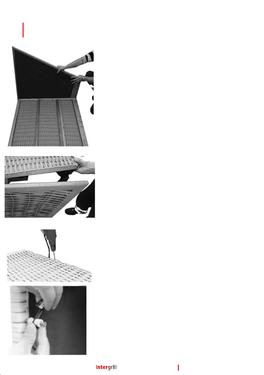
1. Zur Montage des Oberkorbs schrauben Sie zunächst die
Seitenteile (8) mit jeweils 4 Schrauben vom Typ A3 an die
beiden Rückwandkomponenten (9H & 9I) fest. Die untere
Rückwand (9I) wird dabei an der schmalen Seite montiert,
die Scharniere zeigen Richtung Boden. Bei der größeren
Komponente (9H) beachten Sie bitte die Richtungspfeile,
welche am Geflecht befestigt sind.
To assemble the upper part, first screw the side parts (8),
on to the two rear panel components (9H & 9I), by using 4
screws of type A3. The smaller component (9I) is mounted
on the bottom. The hinges must show towards the ground.
Regarding the larger component (9H), please be aware of
the directional arrows, which are attached to the wicker.
2. Die Dachplatte (10) wird nun mit jeweils 2 Schrauben
vom Typ A3 an den Seitenteilen (8) befestigt.
The roof (10) is then fixed with 2 screws of type A3 on the
upper side parts (8).
3. Mit Hilfe von 2 Schrauben (A3) wird die Dachplatte zu-
sätzlich an der Rückwand fixiert. Die entsprechenden Stellen
sind durch Pfeile markiert.
The roof (10) is additionally fixed by two screws of type
(A3) on the rear component (9H). The corresponding points
are marked by two arrows.
4. Zur Befestigung der Markise nutzen Sie bitte Schraube
(A3) inkl. der Kunststoffklemmen (S5). Je eine Klemme um
die Markisenführung stecken und die Schraube an der
markierten Stelle von innen in das Seitenteil schrauben.
To fix the awning (16) please use each 1 screw of type (A3)
and the plastic clamps (S5). Please stick one plastic clamp
around the awning rod and screw the screw at the marked
point from the inside into the upper side part.

9
MONTAGEANLEITUNG
Zusammensetzen von Ober- und Unterkorb
MONTAGEANLEITUNG
Montage der Verstellgriffe
1. Um Ober- und Unterkorb zusammen zu fügen, müssen
Sie die Ösen des Oberkorbs in die U-Profile des Unterkorbs
einhaken.
To add the upper & lower part together, please hook the
eyes of the upper part in the U-sections of the lower part.
WICHTIG
Achten Sie bitte darauf, dass alle drei Ösen richtig verankert
sind.
IMPORTANT
Please be aware, that all three eyes are anchored properly.
Bitte verwenden Sie die abgebildeten Teile für diesen
Montageschritt.
Verstellgriffe Oberkorb (S5)
For the next assembly step, please use the shown parts.
Adjustable handle (S5)
1. Zunächst halten Sie den Oberkorb bitte so zum Unter-
korb, dass sich die bereits vormontierte Schraubplatte am
Oberkorb in der Mitte von zwei Löchern auf der Schiene am
Unterkorb befindet.
Please hold the upper part against the lower part, so that
the pre-assembled plate is located in the middle of two
holes on the rail of the lower part.

10
MONTAGEANLEITUNG
Montage der Verstellgriffe
MONTAGEANLEITUNG
Montage des Stützbügels
2. Stecken Sie nun den Verstellgriff (S5) in ein Loch auf der
Schiene am Unterkorb, halten eine Kunststoffscheibe vor
das Schraubloch am Oberkorb und drehen den Bolzen durch
den Verstellgriff und die Kunststoffscheibe in den Oberkorb.
Now insert the adjustable handle (S5) into a hole on the
rail. Please keep a spacer between the upper and lower part
and screw the bolt through the adjustable handle, and the
spacer into the threaded plate.
WICHTIG
Achten Sie bitte darauf, dass Sie den Bolzen nicht zu stark
eindrehen, er sollte nicht am Holzrahmen Scheuern bzw.
Kratzen.
IMPORTANT
Please do not tighten the bolts too strong, they should not
scrub or scrape on the lower side part.
Bitte verwenden Sie die abgebildeten Teile für diesen
Montageschritt.
Stützbügel (11)
U-Profile Halter mit Schrauben und Hutmuttern (S7)
For the next assembly step, please use the shown parts.
Supportbracket (11)
U-Profiles support bracket (S7)
1. Zur Montage des Stützbügels (11) verbinden Sie bitte die
drei Einzelstücke mittels 2 Schrauben (A1).
To assemble the support bracket (11), please connect the
three components by 2 screws of type (A1).
2. Zur Befestigung des Stützbügels an der Rückseite des
Oberkorbes müssen Sie zunächst die U-Profile (S7) mit je 2
Schrauben (A1) an den markierten Stellen montieren.
For fixing the support bracket (11) to the upper part, you
need to install the U-Profiles (S7) with 2 screws of type
(A1).

11
MONTAGEANLEITUNG
Montage des Stützbügels
MONTAGEANLEITUNG
Einsetzen der Polster
3. Achten Sie bitte darauf, dass der Stützbügel frei
schwingen kann.
Please be aware that the support bracket needs to be
freely movable.
4. Anschließend wird der Stützbügel mit Hilfe der Schrauben
und Hutmuttern (S7) der U-Profile an diesen befestigt.
Afterwards, please screw the support bracket with screws
and cap nuts (S7) into the U-Profiles.
1. Stecken Sie die Rückenpolster (12) zunächst unten in die
dafür vorgesehenen Haken und drücken Sie das Polster
anschließend oben an die Rückwand.
At first please insert the back rest (12) in the provided
hooks.
2. Achten Sie beim Einsetzen der Sitzbank (13) darauf, dass
die Führungsleiste nach vorn zeigt und dass das Polster
richtig aufliegt.
Take care that the guide bar of the seat padding (13) is
facing forward and that it is properly positioned.
3. Bitte befestigen Sie zum Abschluss die Nackenrollen (14)
an den Klettbändern und legen die Wurfkissen (15) in den
Strandkorb.
In the end please attach the bolsters (14) to the Velcro tape
and place the pillow (15) in the beachchair.

Intergrill GmbH
Friedrich-Bessel-Str. 20
50126 Bergheim
Deutschland
Service Hotline
02271 - 467 0158
Stand Februar 2019
Lieferumfang ohne Extras, optionale Bestellung möglich.
Abbildungen, Zeichnungen, Maß- und Gewichtsangaben nur Annäherungswerte.
Es können drucktechnisch bedingte Farbabweichungen auftreten.
Änderungen vorbehalten.
This manual suits for next models
3
Popular Patio Furniture manuals by other brands

Classic Accessories
Classic Accessories Atrium Patio Instructions & Care

Costway
Costway NP11205 manual

Island Umbrella
Island Umbrella sunbrella NU6545 quick start guide

VonHaus
VonHaus 2500335 quick start guide

PATIOJOY
PATIOJOY HW70896 manual

Treasure Garden
Treasure Garden AUTO TILT Assembly and operation guide


HAMPTON BAY
HAMPTON BAY 65-51949 Use and care guide

Home Styles
Home Styles 88 5560 66 quick start guide

HAMPTON BAY
HAMPTON BAY Calabria owner's manual

C.R. Plastic Products
C.R. Plastic Products DSF261 manual

Zest 4 Leisure
Zest 4 Leisure Aquatic Planter Assembly instructions

Blue Wave
Blue Wave Island Umbrella Adriatic NU5433CH quick start guide