Interior technology Assunta RECTA User manual

Assembly Manual

Krommebeekstraat 46
8930 Menen, Belgium
T +32 (0)56 18 59 50
info@interiortechnology.be
www.interiortechnology.be
InteriorTechnology.be is the signboard of the activities of VDS bvba concerning interior automation.
Pag. 2
Table of contents
Table of contents 2
Regulations 3
Panel preparation 4
Panel 1 5
Panel 2 6
Panel 3 7
Installation of guide rails 8
Installation of the lifting drive 9
Connection of the control unit 10
Installation of lower panel 12
Installation of the belts 14
Installation second / third panel 16
Adjustment of the guide blocks 18
Putting the system into operation 20
Installation of the fixed panel 22
Installation of the door aligners 24
Connection of the relay contacts 25
Error codes and user modes 26
Notes 27

Krommebeekstraat 46
8930 Menen, Belgium
T +32 (0)56 18 59 50
info@interiortechnology.be
www.interiortechnology.be
InteriorTechnology.be is the signboard of the activities of VDS bvba concerning interior automation.
Pag. 3
Regulations
Liability
To ensure correct operation of the Assunta system, all steps in this manual must be followed carefully. VDS
BV can never be liable for the use of this manual and shall not be responsible for incorrectly installed sys-
tems.
Guidelines
It is essential that the panels are straight. Therefore, a maximum curvature or torsion of 1.5 mm applies to all
the panels of the system.
Copyright
All rights reserved. Nothing in this publication may be copied, stored in an automated data file or made pu-
blic, in any way or form, be it electronic, mechanical, by means of photocopies, recordings or any other me-
thod without prior written permission from the publisher. © 2023, VDS Verdonck Development & Systems.
This manual is self-published.
Krommebeekstraat 46
8930 Menen, Belgium
T +32 (0)56 18 59 50
info@interiortechnology.be
www.interiortechnology.be
InteriorTechnology.be is the signboard of the activities of VDS bvba concerning interior automation.
Pag. 4
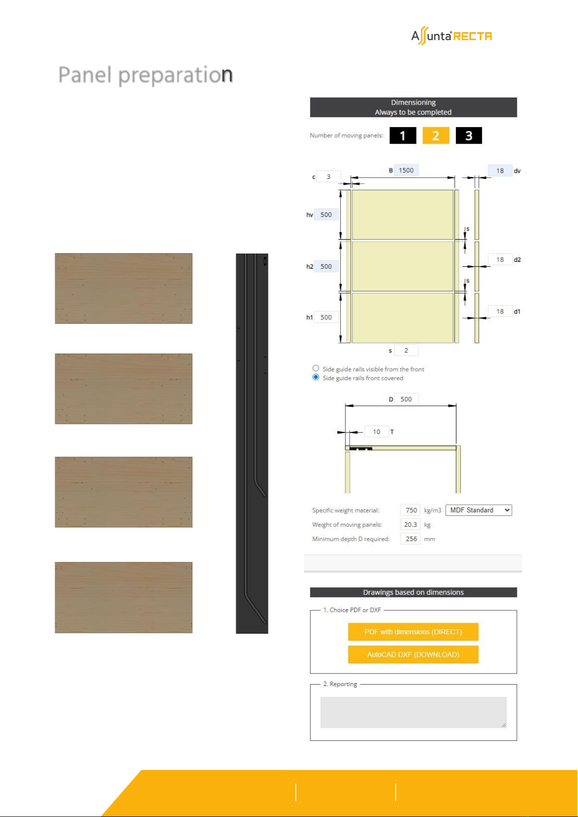
Mill the panels and, if applicable, the side
guide rails according to the drawings from
www.assunta.be. Also drill all the holes..
Panel preparation
Lower panel:
Optional second panel:
Optional third panel:
Fixed panel:
Guide rail:
True-to-scale drawings can be downloaded
from the website www.assunta.be.

Krommebeekstraat 46
8930 Menen, Belgium
T +32 (0)56 18 59 50
info@interiortechnology.be
www.interiortechnology.be
InteriorTechnology.be is the signboard of the activities of VDS bvba concerning interior automation.
Pag. 5
Mount the frames (left and right) for the lower panel on the panel.
Panel 1
For surface mounted panels, provide an intermediate plate
with the correct thickness (Y- d) and the same hole pattern
as the panel. Or attach the intermediate plate BEFORE dril-
ling the panel.
Krommebeekstraat 46
8930 Menen, Belgium
T +32 (0)56 18 59 50
info@interiortechnology.be
www.interiortechnology.be
InteriorTechnology.be is the signboard of the activities of VDS bvba concerning interior automation.
Pag. 6
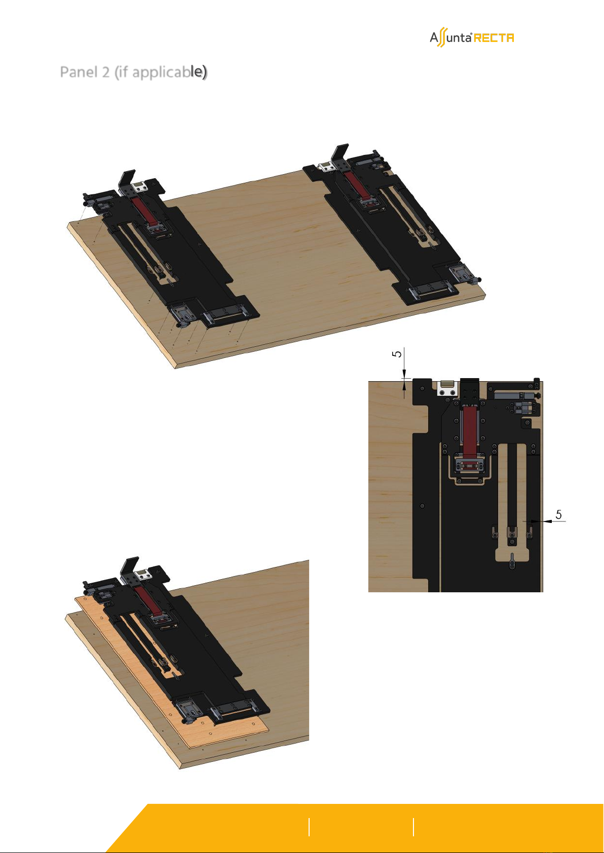
Mount the frames (left and right) for the second panel on the panel..
Panel 2 (if applicable)
For surface mounted panels, provide an intermediate plate
with the correct thickness (Y- d) and the same hole pattern
as the panel. Or attach the intermediate plate BEFORE dril-
ling the panel.

Krommebeekstraat 46
8930 Menen, Belgium
T +32 (0)56 18 59 50
info@interiortechnology.be
www.interiortechnology.be
InteriorTechnology.be is the signboard of the activities of VDS bvba concerning interior automation.
Pag. 7
Mount the frames (left and right) for the third panel on the panel..
Panel 3 (if applicable)
For surface mounted panels, provide an intermediate plate
with the correct thickness (Y- d) and the same hole pattern
as the panel. Or attach the intermediate plate BEFORE dril-
ling the panel.
Krommebeekstraat 46
8930 Menen, Belgium
T +32 (0)56 18 59 50
info@interiortechnology.be
www.interiortechnology.be
InteriorTechnology.be is the signboard of the activities of VDS bvba concerning interior automation.
Pag. 8
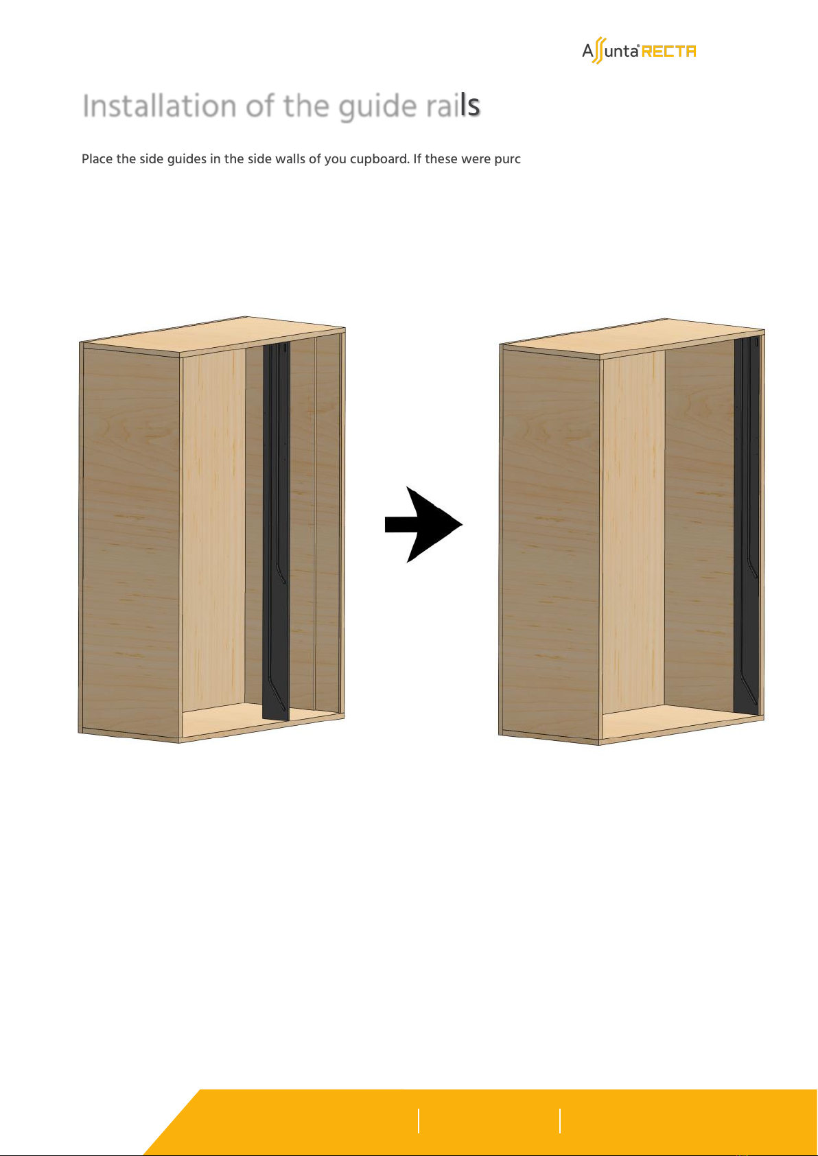
Place the side guides in the side walls of you cupboard. If these were purchased, there is an excess of 35 mm
on the height. Cut these to size at the top.
Installation of the guide rails
Krommebeekstraat 46
8930 Menen, Belgium
T +32 (0)56 18 59 50
info@interiortechnology.be
www.interiortechnology.be
InteriorTechnology.be is the signboard of the activities of VDS bvba concerning interior automation.
Pag. 9
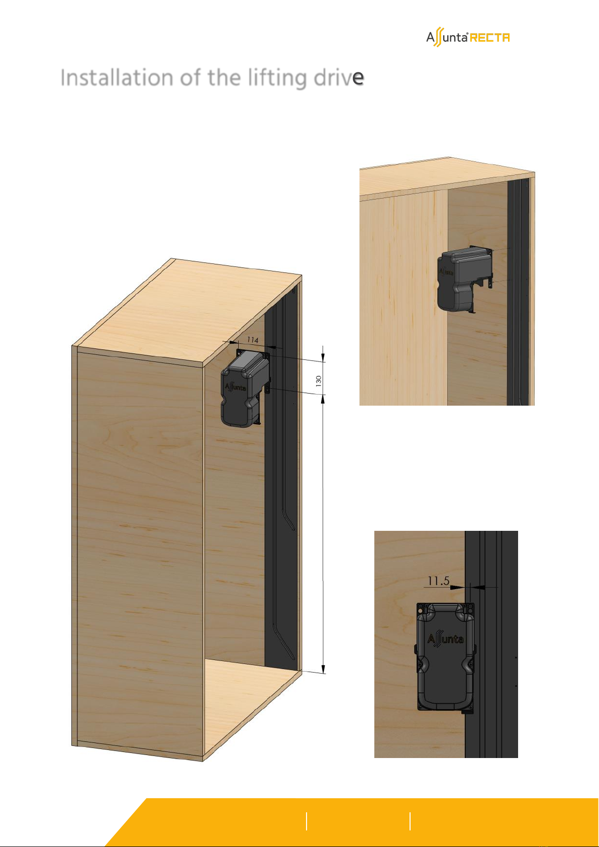
The height dimension for the lower
bore is shown on the drawings availa-
ble at www.assunta.be. The side di-
mension is fixed relative to the side
guide.
Installation of the lifting drive
Place the lifting drives in the cabinet. If the side guides were purchased, the front Ø 3.5 mm holes are already pre-
drilled on the side guides.
Krommebeekstraat 46
8930 Menen, Belgium
T +32 (0)56 18 59 50
info@interiortechnology.be
www.interiortechnology.be
InteriorTechnology.be is the signboard of the activities of VDS bvba concerning interior automation.
Pag. 10
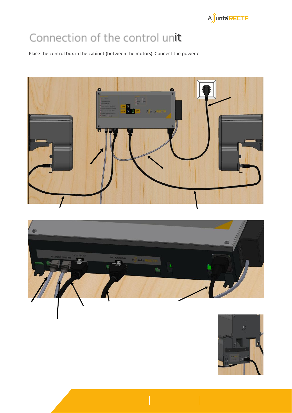
Place the control box in the cabinet (between the motors). Connect the power cable 220V and motor cables
to the control box. Optionally, also connect the remote control receiver and/or cable (Assunta or own) push
buttons.
Connection of the control unit
Power cable
Right-hand motor cable
Left-hand motor cable
RC receiver
Cable
Push buttons
Also connect the motor cables
on the motor side.
Cable
Push buttons
RC receiver
Left-hand motor cable
Right-hand motor cable Power cable
Krommebeekstraat 46
8930 Menen, Belgium
T +32 (0)56 18 59 50
info@interiortechnology.be
www.interiortechnology.be
InteriorTechnology.be is the signboard of the activities of VDS bvba concerning interior automation.
Pag. 11
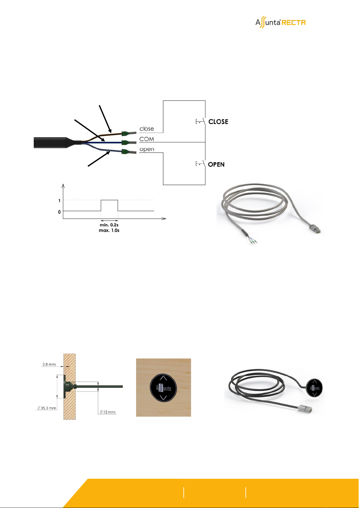
To connect (your own) push buttons or home automation, you will need the button cable. This cable has 3
open threaded ends, one for the upward movement (blue/white), one for the downward movement (brown),
and the outgoing voltage (blue). (No external power supply is therefore required.)
Connect the RJ45 plug to the control cabinet. It must be plugged into the ‘Buttons’ socket.
Proceed as follows to install any Assunta push buttons. Mill a recess according to the drawing below and glue
the buttons in. Connect the RJ45 plug to the control cabinet. It must be plugged into the ‘Buttons’ socket.
Blue
Brown
Blue/white

Krommebeekstraat 46
8930 Menen, Belgium
T +32 (0)56 18 59 50
info@interiortechnology.be
www.interiortechnology.be
InteriorTechnology.be is the signboard of the activities of VDS bvba concerning interior automation.
Pag. 12
On both the left and right sides of the panel, unscrew (not completely!) the adjustment bolt of the top and
guide wheels.
Installation lower panel
Slide the carriage of the guide block inwards.

Krommebeekstraat 46
8930 Menen, Belgium
T +32 (0)56 18 59 50
info@interiortechnology.be
www.interiortechnology.be
InteriorTechnology.be is the signboard of the activities of VDS bvba concerning interior automation.
Pag. 13
Insert the panel with the top wheels retracted into the corpus in such a way that the lower wheels enter
the corresponding slot.
Bring the upper wheel to the level of the slot, slide the wheel into the slot and retighten the adjustment
bolt.

Krommebeekstraat 46
8930 Menen, Belgium
T +32 (0)56 18 59 50
info@interiortechnology.be
www.interiortechnology.be
InteriorTechnology.be is the signboard of the activities of VDS bvba concerning interior automation.
Pag. 14
Put the system in mode 'Slow' by pressing and releasing the 2 control buttons simultaneously when 'S' ap-
pears. This can be done in 3 different ways. With the push buttons, the remote control or the buttons on the
control box.
Lower the belts sufficiently by briefly pressing the Close button to allow the belt clips to be attached to the
lower panel. Press the Close button again to stop the belts.
Push buttons Remote Control Control box
Push buttons Remote Control Control box
or
or or
Mode SLOW
Installation of the belts (on the lower panel)
or

Krommebeekstraat 46
8930 Menen, Belgium
T +32 (0)56 18 59 50
info@interiortechnology.be
www.interiortechnology.be
InteriorTechnology.be is the signboard of the activities of VDS bvba concerning interior automation.
Pag. 15
Screw the end plate of the belts onto the panel. Note well the assembly.
Krommebeekstraat 46
8930 Menen, Belgium
T +32 (0)56 18 59 50
info@interiortechnology.be
www.interiortechnology.be
InteriorTechnology.be is the signboard of the activities of VDS bvba concerning interior automation.
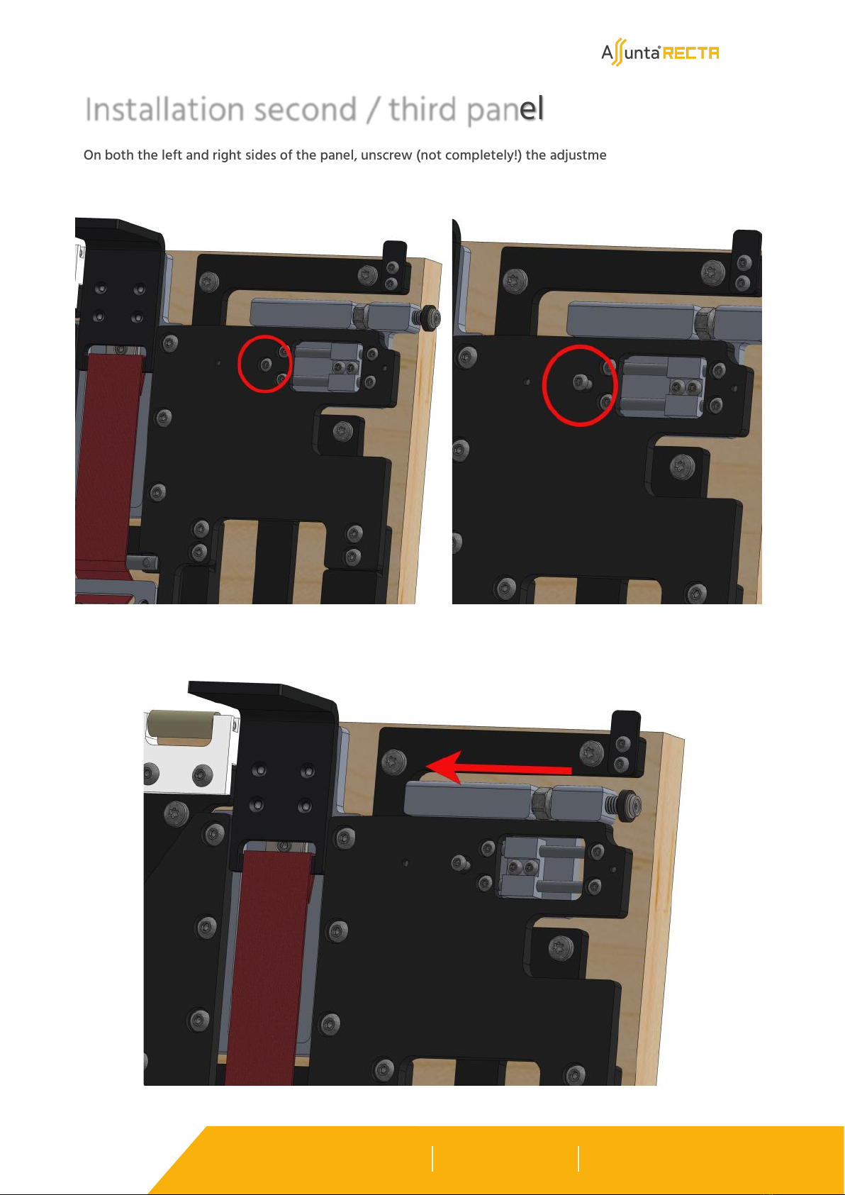
Pag. 16
On both the left and right sides of the panel, unscrew (not completely!) the adjustment bolt of the top and
guide wheels.
Installation second / third panel
Slide the carriage of the guide block inwards.

Krommebeekstraat 46
8930 Menen, Belgium
T +32 (0)56 18 59 50
info@interiortechnology.be
www.interiortechnology.be
InteriorTechnology.be is the signboard of the activities of VDS bvba concerning interior automation.
Pag. 17
Insert the panel with the top wheels retracted into the corpus in such a way that the lower wheels enter
the corresponding slot.
Bring the upper wheel to the level of the slot, slide the wheel into the slot and retighten the adjustment bolt.

Krommebeekstraat 46
8930 Menen, Belgium
T +32 (0)56 18 59 50
info@interiortechnology.be
www.interiortechnology.be
InteriorTechnology.be is the signboard of the activities of VDS bvba concerning interior automation.
Pag. 18
Depth control upper guide blocks.
Adjust the depth of the wheel in the slot by using an Allen key SW 3 to reduce or increase the depth of the
wheel in the slot. Adjust so that on both sides you have adjusted the wheel to within 0.5 mm of the bottom
of the slot.
Adjustment of the guide blocks
Depth control lower guide blocks.
The arrangement is identical to the upper guide wheels.
Krommebeekstraat 46
8930 Menen, Belgium
T +32 (0)56 18 59 50
info@interiortechnology.be
www.interiortechnology.be
InteriorTechnology.be is the signboard of the activities of VDS bvba concerning interior automation.
Pag. 19
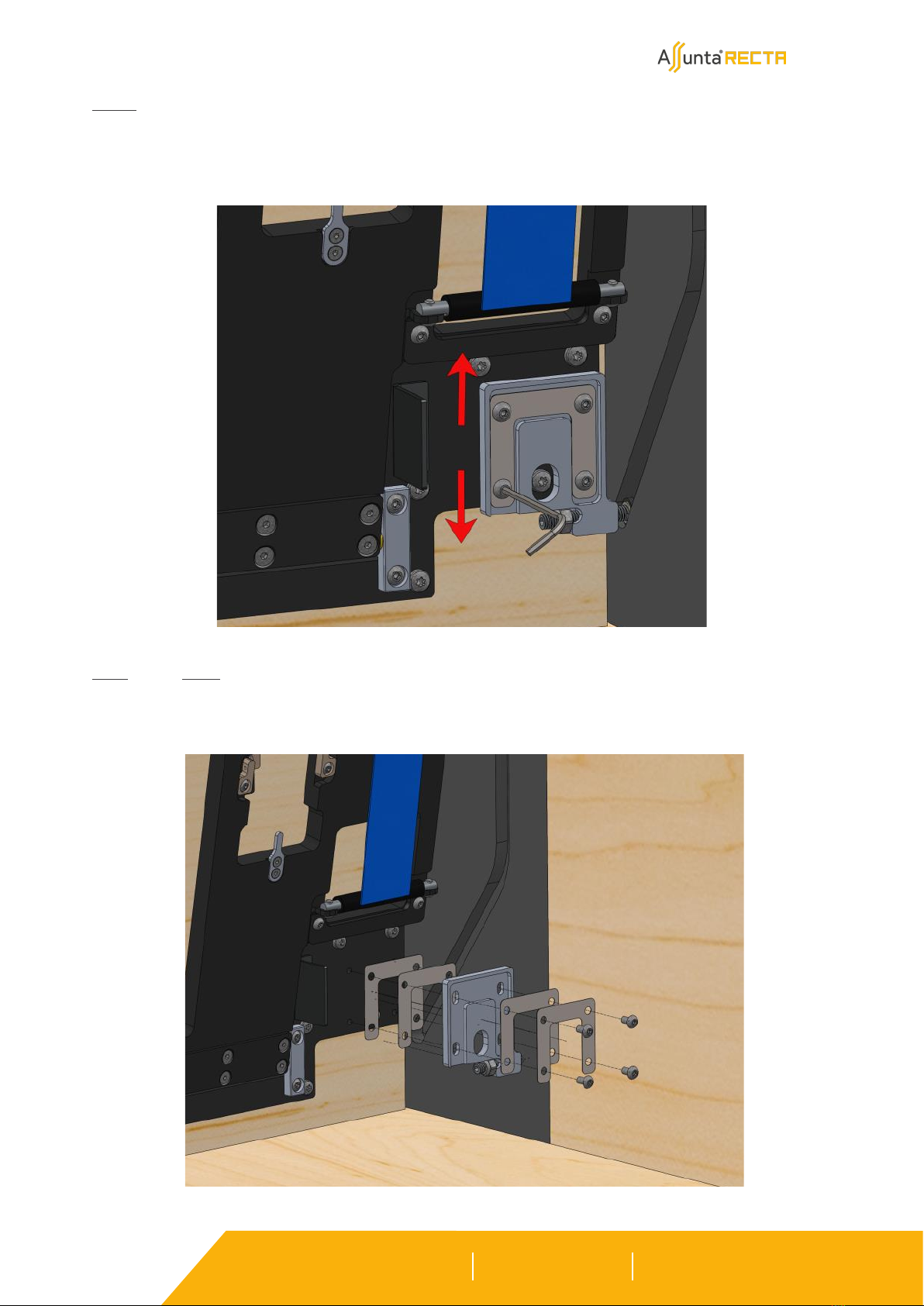
Height control lower guide blocks.
The height of the guide blocks on the panel can be adjusted by loosening the 4 fixing bolts with Allen key
SW 2.5. After moving the block up or down, retighten the bolts.
Front control lower guide blocks.
By placing the thickness plates of 0.2 mm and 0.3 mm either in front of or behind the guide block, the posi-
tion of the guide block relative to the front of the panel can be changed.
Krommebeekstraat 46
8930 Menen, Belgium
T +32 (0)56 18 59 50
info@interiortechnology.be
www.interiortechnology.be
InteriorTechnology.be is the signboard of the activities of VDS bvba concerning interior automation.
Pag. 20
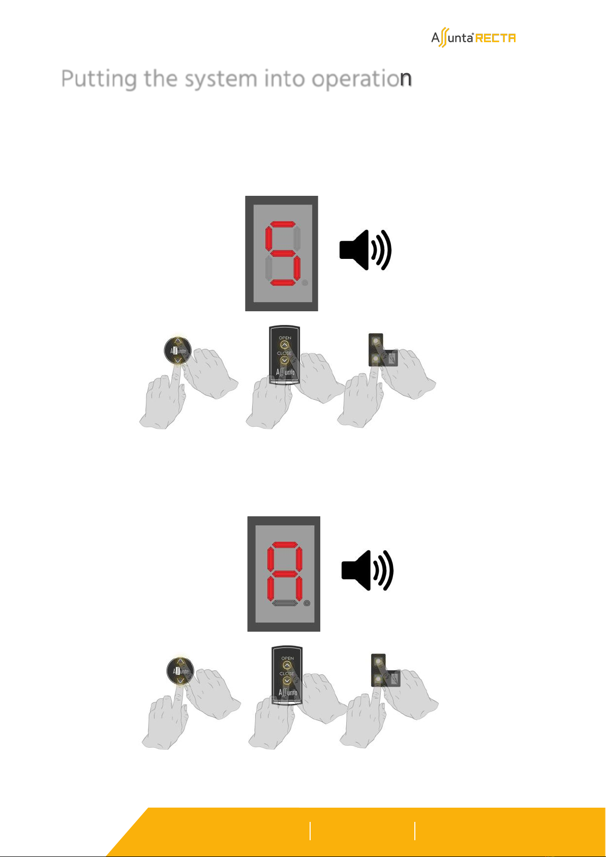
Place in the system in 'ADJUST' mode by pressing and releasing the 2 control buttons simultaneously when 'A'
appears. (You will hear two beeps). The lower panel automatically positions itself on the bottom and the
belts are tightened.
Putting the system into operation
Place in the system in 'SLOW' mode by pressing and releasing the 2 control buttons simultaneously when 'S'
appears (You will hear one beep). You can freely move the panels up and down by pressing UP/OPEN or CLO-
SE/DOWN. The panels move slowly, allowing you to check proper operation. With a small increase in the for-
ce the motors have to deliver, the system goes into safety and the motors stop. By pressing again, you can
continue.
Mode SLOW 1X
Push buttons Remote Control Stuurkast
or or
Mode AJUST
or or
2X
Push buttons Remote Control Control box
Table of contents
Other Interior technology Indoor Furnishing manuals

Popular Indoor Furnishing manuals by other brands

Dorel Living
Dorel Living DL8559-LS manual

Signature Design by Ashley
Signature Design by Ashley W283-68 Assembly instructions

Lifetime
Lifetime 60170 Assembly instructions

Super Amart
Super Amart 58360 Assembly instruction

YitaHome
YitaHome FTLFCT-0013 Assembly instructions

Next
Next 661168 Assembly instructions


