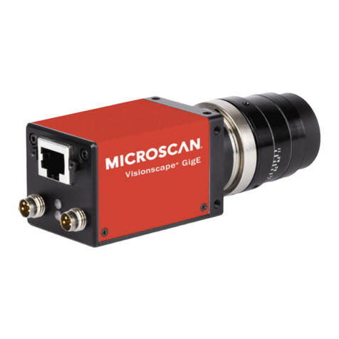
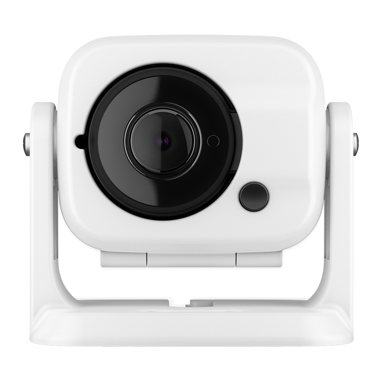
Intevac MicroVista NIR User manual

Intevac, Inc.
3560 Bassett Street
Santa Clara, CA
95054-2704
MicroVista®NIR and UV Cameras
User Manual
User Manual

MicroVista Camera User Manual ICD0057 Rev 1
2 Imaging Support: imagin[email protected] http://www.mosir950.com 408-496-2019
1WARNINGS AND SAFETY PRECAUTIONS
Electric Shock Hazard
Static Electricity
IMPORTANT: Any changes or modifications not expressly approved in this
manual may void the manufacturer’s warranty.
This symbol is intended to alert the user to the presence of important operating
and maintenance (servicing) information in the literature accompanying the
appliance.
To prevent fire or shock hazard, do not expose the unit to rain or moisture.
The components in this camera are susceptible to static electricity. Do not open
camera. There are no user serviceable parts inside. Contact Intevac, Inc. for
any problems or repairs.

MicroVista Camera User Manual
Imaging Support: imaging@intevac.com http://www.mosir950.com 408-496-2019 3
In Case of Problem
Handle with Care
Cleaning
Protect from High Temperatures
Do Not Open or Modify
Protect from Humidity and Dust
Do not use the camera if smoke (or a strange odor) emanates from the unit, or
if there are any other apparent electrical problems. Disconnect the power cable
immediately and consult the manufacturer (or authorized reseller).
Proper care should be taken when transporting or handling the camera.
Prolonged vibration, or dropping the camera can damage components.
Dirt may be removed from the exterior case by wiping it with a soft cloth. To
remove stains, wipe with a soft cloth lightly moistened with a gentle detergent
solution. Wipe with a dry cloth after cleaning. Do not use a benzene, thinner, or
other chemical product on the camera case, as that may cause discoloration or
deformation.
Do not install close to heat generating devices, such as spotlights or
generators, etc. Install where the temperature range is between -10°C and
40°C.
Do not open the camera case, as it may be dangerous and cause damage to
the unit. For internal settings and repairs, consult the manufacturer (or Intevac
authorized reseller).
To prevent camera damage, do not install it where there is smoke or steam,
where dampness may reach high levels, or where there is excessive dust.

MicroVista Camera User Manual ICD0057 Rev 1
4 Imaging Support: imagin[email protected] http://www.mosir950.com 408-496-2019
2CAMERA OVERVIEW
Introduction
MicroVista®cameras are back-illuminated CMOS cameras optimized for
ultraviolet (UV) and near-infrared (NIR) response. The combination of 100% fill-
factor and high Quantum Efficiency (QE) from proprietary coatings provides
sensitivity comparable to scientific-grade CCD cameras. The MicroVista®camera
has a 1.3 megapixel resolution and 30 frames per second full frame digital
readout via CameraLink. The camera has a small form factor, low power
consumption, and is ideal for high sensitivity video rate imaging.
Camera Features
•Image
•Programmable AGC
•Windowing (Region of Interest)
•Image Orientation (Horizontal Flip)
•Digital Zoom
•Histogram Equalization
•Software Interface
•Windows XP and Windows 2000
•MicroVista®GUI Application
•MicroVista®SDK
•Hardware Interface
•CameraLink for video output
•RS-232 or CameraLink for camera control

MicroVista Camera User Manual
Imaging Support: imaging@intevac.com http://www.mosir950.com 408-496-2019 5
•Power Consumption: 2 Watts @ 3.6 VDC
•Camera Description
•Lens Interface: C-mount, 1" optical format
•Camera Mount: 1/4"-20
•Exposure Range: 30 μsec to 6 seconds (Rolling Shutter), 30 μs to
270 ms (Pseudo-Snapshot)
•Shutter Type: Rolling
CMOS Operation
Rolling Shutter
MicroVista®operates in a mode called Rolling Shutter. It is the most common
mode of readout for CMOS imaging devices. In Rolling Shutter readout mode,
each row of the sensor is accessed sequentially from the first to the last row. After
each row is read out, it is reset before it starts integrating the next exposure.
When the reset period ends, the row integrates light until it is addressed again in
the next image frame. The time interval from row to row is constant, so all rows
receive the same amount of exposure time, but the readout is sequential, so the
rows are not all exposed simultaneously.
The length of time that the row is held in reset determines the exposure time for
that row. A row with a very short reset period will have a relatively long exposure
period, and vice versa. For example, running at 30 frames per second gives a
readout time of 33.33 milliseconds per frame. If there are 1024 rows, then each
row will require 0.03 ms to read out. If each row is subsequently held in reset for
23.33 ms, then each row will have 10 ms of exposure per frame. (The minimum
reset time for the MicroVista®CMOS device, also known as the row blanking time,
is 3.45 µs.)
Pseudo-Snapshot
It is possible for a rolling shutter device to emulate a snapshot shutter device by
using a modification of the readout called Pseudo-Snapshot. Normally, a Rolling

MicroVista Camera User Manual ICD0057 Rev 1
6 Imaging Support: imagin[email protected] http://www.mosir950.com 408-496-2019
Shutter device goes immediately from the last row of a frame to the first row of the
next frame. In Pseudo-Snapshot mode, the device instead waits for a period of
time after reading the last row before starting the first row of the next frame.
During this waiting period, the entire device is being exposed at the same time,
like a snapshot shutter. After the waiting period, rolling shutter readout resumes.
For example, a MicroVista®is put in Pseudo-Snapshot mode with an exposure
time of 50 ms. The Rolling Shutter readout time for the MicroVista®is 33.33 ms. If
the frame begins at time 0, then the first row will be exposed for time t=0.00 to
t=50.00 ms; the second row will be exposed for time t=0.03 to t=50.03 ms, and the
last row will be exposed for time t=33.30 to t=83.30 ms. From time t=33.30 to
t=50.00 ms, all rows are exposing at the same time.
Motion Artifacts
Due to the way rolling shutter reads out, it is susceptible to certain motion
artifacts. Since each row sees a slightly different time slice, fast moving objects
can get stretched out. Objects moving from left to right or right to left will be
slanted in the direction of motion. Objects moving from top to bottom will be
elongated, and objects moving from bottom to top will be shortened.
Rolling Shutter Frame Rate
In Rolling Shutter mode, it is possible to lower the frame rate (increase exposure
time) without resorting to Pseudo-Snapshot mode. Increasing the interline delay
(reset time for each row) will increase the time it takes to go from one row to the
next, and thus the total readout time for a frame. For example, the minimum row
blanking time of 3.45 μs plus the 29.09 μs of row readout gives a frame rate of 30
fps (33.33 ms) for 1024 rows. Increasing the row blanking time to 166.23 μs will
increase the readout time to 200.01 ms for 1024 rows for a frame rate of 5 fps.
Windowing
The MicroVista®is capable of changing the size of the image area that is read out.
Setting a specific window in the image allows the camera to read out that
particular portion of the image area at a much higher frame rate than a full frame.
The size and location of the window are defined by the starting row and column
and ending row and column of a rectangle. The only restrictions on the window
parameters are that the starting and ending column must be between 1 and 1280
and divisible by 8, and the starting and ending row must be between 1 and 1024.

MicroVista Camera User Manual
Imaging Support: imaging@intevac.com http://www.mosir950.com 408-496-2019 7
To calculate the readout time of a particular window, use the following equation:
The following table lists readout times and frame rates for some common window
sizes:
Window Size Readout Time Frame Rate
1280 x 1024 33327 µs 30 Hz
640 x 512 9216 µs 109 Hz
320 x 256 2746 µs 364 Hz
160 x 128 908 µs 1102 Hz
80 x 64 337 µs 2963 Hz
tread = ((colend -col
start + 1) ×tpixel + treset)×(rowend - rowstart +1)
treset = 152 ×tpixel = 3.4545 µs
tpixel = ----------- = 0.0227 µs
1
44 MHz

MicroVista Camera User Manual ICD0057 Rev 1
8 Imaging Support: imagin[email protected] http://www.mosir950.com 408-496-2019
Camera Specifications
Video Communication: CameraLink and RS-232
Power Consumption: 2 Watts at 3.6 VDC
Cooling: Passive air cooling (no fan required)
Image Device: Back illuminated CMOS, anti-reflection coating to optimize
near infrared (NIR) or UV response (depending on model)
Image Size: 13.8 x 11.06 mm; 17.7 mm diagonal
Resolution: 1.3 million pixels (1280 x 1024)
Pixel Size 10.8 µm square
Fill Factor: 100%
System Read Noise: 40 e-rms (typical)
Spectrometric Well Capacity: 40 ke-(typical)
Dark Current: 150 e-/p/s (typical)
Lens Mount: C-mount, 1” optical format
Camera Mount: 1/4"-20
Shutter Type: Rolling
Exposure Range: 30 µs to 6 seconds, depending on region of interest (ROI)
ROI (Windowing): Software selectable
Frame Rate vs. ROI: 1280 x 1028: 30 fps
512 x 512: 29 fps
128 x 128: 1230 fps
Digital Output Bit Depth: 10 bit monochrome
Environmental: Operating Temperature: 0°C to +50°C
Humidity: 5% to 95% non-condensing
Weight: 225 grams
Dimensions (WxHxD): 2" x 2" x 3"

MicroVista Camera User Manual
Imaging Support: imaging@intevac.com http://www.mosir950.com 408-496-2019 9
QE Response Curve
Figure 1: QE Response Curve of MicroVista®UV Camera
Figure 2: QE Response Curve of MicroVista®NIR Camera
esnopseREQlacipyT
%0
%01
%02
%03
%04
%05
%06
%07
%08
%09
%001
00110001009008007006005004003002001
)mn(htgnelevaW
Quantum Efficiency (%)
VU
esnopseREQlacipyT
%0
%01
%02
%03
%04
%05
%06
%07
%08
%09
%001
00110001009008007006005004003002
)mn(htgnelevaW
Quantum Efficiency (%)
RI

MicroVista Camera User Manual ICD0057 Rev 1
10 Imaging Support: imagin[email protected] http://www.mosir950.com 408-496-2019
Camera Dimensions
Figure 3: Camera Dimensions

MicroVista Camera User Manual
Imaging Support: imaging@intevac.com http://www.mosir950.com 408-496-2019 11
Optical Interface
The MicroVista®camera is designed to operate with a 1” C-mount lens. Intevac
recommends using a 1” C-mount lens to avoid vignetting the image area.
Figure 4: Optical Interface
The sensor has an input window made of UV-grade fused silicon. The window is
2mm thick and is AR-coated for maximum transmission. (NIR and UV versions
have different AR coating.)
NOTE: Standard lenses invert the projected image. The MicroVista®sensor is
oriented to account for that. The displayed video output will appear
normal.
<<UPDATE>>

MicroVista Camera User Manual ICD0057 Rev 1
12 Imaging Support: imagin[email protected] http://www.mosir950.com 408-496-2019
Back Focus Adjustment
Longitudinal Adjustment
The lens mount, when flush with the front plane of the camera, determines the
nominal position for a C-mount lens. If necessary to adjust the C-mount relative to
the sensor focal plane, refer to Figure 5: Alignment Location Detail for the
location of the 10-32 set screw. To loosen, rotate the screw counter-clockwise.
With the setscrew loosened, the lens mount can be moved in and out to adjust the
focal plane location. When the desired position is obtained, turn the screw
clockwise to tighten and retain the lens mount position.
Figure 5: Alignment Location Detail

MicroVista Camera User Manual
Imaging Support: imaging@intevac.com http://www.mosir950.com 408-496-2019 13
3CAMERA SETUP
Introduction
The MicroVista®camera is operational within 20 seconds of connection of power
and lens. To view or record live video, the user must connect the camera to a
computer equipped with a frame grabber and the CameraLink communications
interface.
Shipped Items
•MicroVista®Camera, near infrared (NIR) or UV
•Camera Configuration Software (GUI) and software development kit
(SDK) (CD)
•MicroVista®Quick Start Guide (hard copy) and User Manual (CD)
•Male-to-Male MDR CameraLink Cable
•Adapter: 90V - 264V AC to 3.6V DC, 1.22A
•Extension power/serial cable, E3010-C
•Transition power/serial cable, E3010-C

MicroVista Camera User Manual ICD0057 Rev 1
14 Imaging Support: imagin[email protected] http://www.mosir950.com 408-496-2019
System Requirements
•3.6V DC power source @ 1.22A
•Frame grabber that accepts Base CameraLink configuration video at 44
MHz or faster
•Windows-based PC:
2Ghz processor speed (suggested)
Computer monitor (1280 x 1024 or greater is recommended)
CD/ROM drive
Operating system: Windows Vista, Windows XP, or Windows 2000
Installing the Camera
Please read through all of these instructions and review the associated figure
before installing the camera. The MicroVista®Quick Start Guide can also be used
as a reference during installation.
1. Install the CameraLink frame grabber software and capture card
following the manufacturer’s instructions.
2. Install the MicroVista®GUI from the Intevac CD.
3. Connect the CameraLink data cable to the MicroVista®and the frame
grabber.
4. Connect the transition power/serial cable (with round mini-DIN
connector) to the camera.
5. (Optional) Connect the 9-pin serial connector to the serial port of the
computer.
6. Plug the 2-prong power adapter into an appropriate power socket.
7. Connect the power adapter to the transition power/serial cable. The
camera starts generating video within 30 seconds of powering up.
By default, the MicroVista®outputs 1280 wide by 1024 high resolution of 10-bit
monochrome video through a single channel. You may need to changeyour frame
grabber’s capture parameters to reflect this. Camera files for the Imperx
FrameLinkTM and National Instruments NI-IMAQTM are included on the CD.

MicroVista Camera User Manual
Imaging Support: imaging@intevac.com http://www.mosir950.com 408-496-2019 15
Use the frame grabber manufacturer’s software to capture video from the camera.
Further information is given in the user manual supplied with the frame grabber.
Use the MicroVista®GUI to control the features of the camera.

MicroVista Camera User Manual ICD0057 Rev 1
16 Imaging Support: imagin[email protected] http://www.mosir950.com 408-496-2019
Figure 6: Camera Installation

MicroVista Camera User Manual
Imaging Support: imaging@intevac.com http://www.mosir950.com 408-496-2019 17
Troubleshooting
If the camera does not operate (no video signal) after 30 seconds, check the
following:
1. Are all cables correctly and securely connected?
2. Is the power supply working with a proper voltage?
3. Is the lens cap removed, the iris open and the focus properly set?
4. Are the frame grabber card and PC set up and functioning properly?
If the camera is not responding to GUI commands, check the following:
1. Camera is receiving power.
2. Check port settings. If using RS-232, settings should read as shown
in Figure 7: COM Port Properties Window. If using Camera Link
serial, the bits per second should be set to 38400. (The MicroVista®
GUI attempts to set this automatically, but some frame grabbers may
need to be set manually.)
Figure 7: COM Port Properties Window
3. Once settings are properly configured, cycle the power (disconnect/
reconnect) and re-attempt to connect to the camera.
38400

MicroVista Camera User Manual ICD0057 Rev 1
18 Imaging Support: imagin[email protected] http://www.mosir950.com 408-496-2019
4MICROVISTA®GUI
The Intevac MicroVista®Graphical User Interface (GUI) is divided into four tabs:
Connect, Windowing, Video Mode, and Video Processing. The status line at the
bottom of the GUI window displays the current camera status (Connected or Not
Connected).
Connect
This window allows the user to set the Port Configuration settings for the
MicroVista®camera. See Figure 8: Connect Tab.
Figure 8: Connect Tab
Port Configuration
This section is used to select which port should be used for communicating with
the MicroVista®camera. Once the desired port has been selected, press the
Connect button to connect to the camera.
NOTE: Once communication is established with the camera, the port
configuration cannot be changed until the camera has been powered off
and back on.
Serial This sets the COM port to allow communication between the PC
and the camera. This is the default setting.
Camera Link Select this option to use the CameraLink Frame Grabber port
for communication with the camera.

MicroVista Camera User Manual
Imaging Support: imaging@intevac.com http://www.mosir950.com 408-496-2019 19
Display Image
This section can be used to provide a live view of the camera video output.
NOTE: This option is currently only available to users with an Imperx
FrameLinkTM card.
Version
Click the Version button to view the current version information in the dialog box
below.
Windowing
This window allows the user to select a specific portion of the image area to view
by setting the starting and ending X and Y pixels of the image to read out. Smaller
windows allow the MicroVista®to output video at faster frame rates. See Figure
9: Windowing Tab.
Figure 9: Windowing Tab
Window Settings
This section is used to set the camera start and stop pixels.
NOTE: The X Start and X Stop values must be divisible by 8.
Start Set the pixel start points for the X and Y axes.
Stop Set the pixel stop points for the X and Y axes.
Set Use the Set button to save the new window settings.
Output Indicates the resolution of the video output.

MicroVista Camera User Manual ICD0057 Rev 1
20 Imaging Support: imagin[email protected] http://www.mosir950.com 408-496-2019
Zoom
This pull-down menu allows the user to change the resolution (in pixels) of the
video output. Zoom factors of 0.5 and 0.625 will digitally average the pixel data to
give a lower resolution image. Zoom factors of 2, 4, and 8 will interpolate the pixel
data to give a higher resolution image. The maximum output size is 2560 x 2048.
Flip
This button allows the user to flip the image along its vertical axis to make it
appear like a mirror image. This feature can be used to compensate for capturing
a reflected image.
Video Mode
This window allows the user to control the video settings for the MicroVista®
camera. See Figure 10: Video Mode Tab.
Figure 10: Video Mode Tab
Video Mode
This section is used to define the sensor used for video output. The MicroVista®
operates in two modes: Rolling Shutter, and Pseudo-Snapshot.
Rolling
Shutter In Rolling Shutter mode, the camera accepts a user requested
frame rate, and adjusts the interline delay time to achieve that
frame rate. This allows the camera AGC (auto-exposure control)
to operate regardless of the frame rate, but exaggerates the
motion artifacts associated with rolling shutter CMOS devices.
Pseudo-
Snapshot In Pseudo-Snapshot mode, the camera accepts an exposure
time, and adjusts the inter-frame delay to achieve that exposure
time. If the exposure time is less than the frame readout time,
then the camera adjusts the intra-frame integration time.
This manual suits for next models
1
Table of contents
