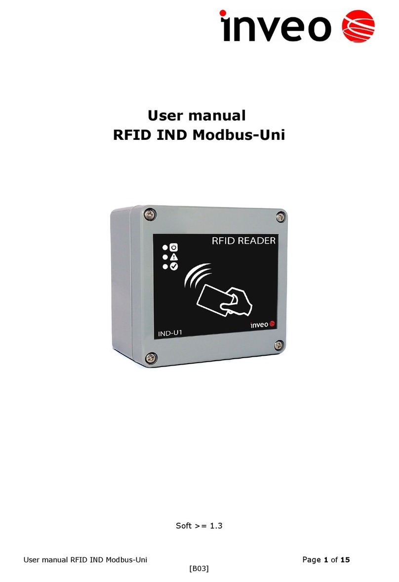
inveo RFID-MB-10 User manual

User manual
RFID MODBUS Reader
RFID-MB-10
INVEO s.c.
ul. Rzemieślnicza 21
43-340 Kozy
tel: +48 785552252
www.inveo.com.pl

Dear Customer!
Thank you very much for choosing our product. Before its use, please read these instructions
carefully. There are given here the most appropriate ways of dealing with this device, the basic
principles of safety and maintenance. Please also keep the user manual so that you can read it
during later use.
Remember!
The manufacturer s not l able for any damage caused by mproper use of the dev ce
for ts ntended purpose or mproper handl ng, as well as fault dr ver result ng from mproper
use.

Table of contents:
1 PURPOSE OF THE DEVICE........................................................................................................4
2 WARRANTY AND LIABILITY OF THE MANUFACTURER.................................................4
3 SAFETY GUIDELINES.................................................................................................................5
3.1 PO ER SUPPLY.............................................................................................................................5
3.2 STORAGE, ORKING ENVIRONMENT AND TRANSPORTATION.......................................................5
3.3 INSTALLATION AND USE OF THE MODULE....................................................................................5
3.4 UTILISATION OF THE MODULEA...................................................................................................5
4 CONSTRUCTION EQUIPMENT.................................................................................................6
4.1 GENERAL FEATURES.....................................................................................................................6
5 DEVICE CONFIGURATION........................................................................................................7
5.1 OUT MODE..................................................................................................................................7
5.2 OUTPUT CONTROL - OUT STATE TEST.........................................................................................8
5.3 READING CARD NUMBER - CARD SERIAL NUMBER.....................................................................8
5.4 RS485 – CONFIGURATION OF TRANSMISSION RS485..................................................................8
6 MODBUS SUPPORT......................................................................................................................9
6.2 MODBUS ADDRESSES.................................................................................................................9
7 TERMINALS DESCRIPTION....................................................................................................11
NOTES.............................................................................................................................................12
Before start ng work w th the controller, read The User manual and follow the nstruct ons
conta ned there n!

1Purpose of the dev ce
RFID MODBUS-10 is used to read the UNIQUE transponders code
Transponder code is available using the MODBUS RTU protocol.
2 Warranty and l ab l ty of the manufacturer
The manufacturer provides a 2-year warranty on the module. The manufacturer also provides post-
warranty service for 10 years from the date of the introducing the module on the market. The
warranty covers all defects in material and workmanship
The manufacturer undertakes to comply with the contract of guarantee, if the following conditions
are met::
•all repairs, alterations, extensions and device calibrations are performed by the manufacturer
or authorized service,
supply network installation meets applicable standards in this regard,
the device is operated in accordance with the recommendations outlined in this manual
the device is used as intended.
The manufacturer assumes no responsibility for consequences resulting from improper installation,
improper use of the module, not following this manual and the repairs of the module by individuals
without permission.
Th s dev ce doesn’t conta n serv ceable parts. The repa rs can be done only by manufacturers
approved repa r serv ce.

3 Safety gu del nes
The module has been constructed using modern electronic components, according to the latest
trends in the global electronics.
3.1 Power supply
The module is adapted to supply DC 10-24V.
3.2 Storage, working environment and transportation
The module has to be used in closed environments free from fumes and corrosive atmosphere.
Environmental conditions for storage:
temperature from + 5°C to +45°C,
relative humidity does not exceed 75%,
atmospheric pressure is in the range 700 – 1060hPa.
Environmental conditions for use:
temperature from +10°C to +30°C,
relative humidity from 30% to 75%,
atmospheric pressure is in the range 700 – 1060hPa.
Recommended conditions for transportation:
temperature from -10°C to +45°C,
humidity from 20 to 95%,
atmospheric pressure is in the range 700 – 1060hPa.
3.3 Installation and use of the module
The module should be used follow ng the gu del nes shown n next part of the user manual.
3.4 Utilisation of the modulea
hen it becomes necessary to liquidate the device (e.g., after the time of use), please contact the
manufacturer or its representative, who are obliged to respond appropriately, i.e., collecting the
module from the user. You can also ask the companies involved in utilization and / or liquidation of
electrical or computer equipment. Under no circumstances should you place the device along with
other garbage.

4 Construct on equ pment
4.1 eneral features
Reader is equipped with RS485 port supports MODBUS RTU protocol and a USB port used to
configure the module.
The device is equipped with one relay output.
4.2 Techn cal data:
Power supply: 10-24VDC
Supply current: 15mA (12V)
Transponders:
Supported transponders: UNIQUE
Carrier frequency: 125kHz
Coding: Manchester
Reading distance: 10cm
Communication:
1 port compatible with RS485
USB port for configuration
Support MODBUS RTU protocol
Input / Output
1 relay output
Mode "Safety mode" switching output in the selected state in caso of the absence of
communication. Ability to set the output status after switching power supply.
Dimensions:
Height: 41,0 mm
idth: 74,5 mm
Length: 89,4 mm

5 Dev ce Conf gurat on
After installing RFID Config configuration and run it, connect the USB cable to the computer and
the module (in this case, an external power supply module is not required - the device is fed through
the USB port).
Draw ng 1. Apl cat on w ndow.
5.1 OUT mode
Mode – Set the output mode , selected from:
Static – bistable mode
Toggle – momentary mode – alternately turning on and off
1-Pulse – release the output causes it activation for time T me ON and after it will switch
off.
Charts work shown in the figure below:
Static mode
t
on
t
off
t
on
t
off
t
on
t
off
t
on

Toogle mode
1-Pulse mode
Power On State – output status after power supply switching on and in Safety mode
T me On – time of output switching on in Toggle and 1-Pulse modes.
T me Off – time of outpput switching off in Toggle mode.
5.2 Output control - Out State Test
This field is used to test outpput. In possition OUT1 it switches on or off the output.
5.3 Reading card number - Card Serial Number
Field shows the last read transponder code.
5.4 RS485 – Configuration of transmission RS485
The field is used to configure the device communication.
MODE (setting 9 bit transmission):
None
Odd
Even
Mark – bit ‘1’ (the same mode as the double stop)
Space – bit ‘0’
BaudRate – field to select baud rate
Dev ce Address – address of the device that will be in the MODBUS network
T meOut – time (given in 100 ms) after which, in case of the absence of transmission, the device
goes into failure (Safety mode) and the Timeout flag will be set.
Safety mode enable – activation of outputs control in case of the absence of communication.
t
on

6 MODBUS support
The device supports the following MODBUS RTU functions:
- 0x01 Read Coils
- 0x03 Read Holding Register
- 0x05 rite Single Coil
- 0x06 rite Single Register
- 0x0F rite Multiple Coils
- 0x10 rite Multiple Registers
6.1
6.2 MODBUS addresses
O. Address Type R/W Descr pt on
1 1000 Holding
Reg
R Transponder code [0]
2 1001 Holding
Reg
R Transponder code [1]
3 1002 Holding
Reg
R Transponder code [2]
4 1003 Holding
Reg
R Transponder code [3]
5 1004 Holding
Reg
R Transponder code [4]
6 1005 Holding
Reg
R Device model
7 1006 Holding
Reg
R Software version
8 1007 Holding
Reg
R Hardware version
9 1008 Holding
Reg
R Output state after switching and in Safety mode
10 1009 Holding
Reg
R Time of communication failure followed by a
transition in to Safety mode
11 1010 Holding
Reg
R The flag of switching the output operation mode
during a failure (Safety Enable)
12 1011 Holding
Reg
R/ Output mode:
0 – Inactive
1 – Bistable
2 – Astable
3 – 1 impuls
13 1012 Holding
Reg
R/ Time of output switching on ( * 100ms)
14 1013 Holding
Reg
R/ Time of output switching off (*100ms)
15 1000 Single Coil R/ Output switching on
16 1001 Single Coil R/ Reserve
17 1002 Single Coil R Output mode
18 1003 Single Coil R Reserve
19 1004 Single Coil R/ Reading flag
Reading: 1 – read a new transponder

Record: 0 – reset reading flag
20 1005 Single Coil R/ Status reset
Reading: 1 – there was a restart of the reader (ex.
through power failure)
Record: 1 – forcing a device reset
0 – Restart flag reset
21 1006 Single Coil R/ Safety status
Reading: 1 – Has been Safety mode triggered
Record: 0 – Flag reset
22 1007 Single Coil R/ RS485 status
Reading: 1 – Has beenTimeout of communication
RS485
Record 0 – Flag reset
23 1008 Single Coil R Input mode
Reading: 1 – active input, 0 – inactive input
(OPTION)
In case of no recording of new event of transponder code reading in Holding Register 1000-
1004 appear random data. Correct number shows only in the moment of reading new event,
indicated by setting the registry Single Coil 1004 (1- read a new transponder). The next reading of
the transponder is only possible after resetting the reading flag and entered „zero” into the 1004
register
Changing the output parameters for MODBUS, is not stored in it is stored in module volatile
memory. It means that after the restart or turn into the Safety mode there will be restored output
parameters previously writing to the EEPROM via USB.
Triggered of the Safety mode restores output settings stored in the EEPROM. It means that times of
switching on, of and output mode are overwritten. After exit Safety mode, if it's demanded all
output parameters should be set again by MODBUS

7 Term nals descr pt on
View of the device board is shown in the figure below.
Draw ng 2. Term nals descr pt on
Nazwa Op s
Power Power connector 12-24VDC
Relay Relay output
max 1 A when 30 VDC
max 0.5 A when 125 VAC
RS485 Communication port
Power LED LED indicates power connection to the module
Status LED LED indicates operation of the relay
USB USB port -module configuration
Antena Connector for antenna
View of the device after removing the cover of the antennas.
Draw ng 3. V ew of the dev ce after remov ng th cover

Notes
…………………………………………………………………………………………………………
…………………………………………………………………………………………………………
…………………………………………………………………………………………………………
…………………………………………………………………………………………………………
…………..
…………………………………………………………………………………………………………
…………………………………………………………………………………………………………
…………………………………………………………………………………………………………
…………………………………………………………………………………………………………
…………..
…………………………………………………………………………………………………………
…………………………………………………………………………………………………………
…………………………………………………………………………………………………………
…………………………………………………………………………………………………………
…………..
…………………………………………………………………………………………………………
…………………………………………………………………………………………………………
…………………………………………………………………………………………………………
…………………………………………………………………………………………………………
…………..
…………………………………………………………………………………………………………
…………………………………………………………………………………………………………
…………………………………………………………………………………………………………
…………………………………………………………………………………………………………

…………..
…………………………………………………………………………………………………………
……………………………………..
…………………………………………………………………………………………………………
…………………………………………………………………………………………………………
…………………………………………………………………………………………………………
…………………………………………………………………………………………………………
…………..
…………………………………………………………………………………………………………
…………………………………………………………………………………………………………
…………………………………………………………………………………………………………
…………………………………………………………………………………………………………
…………..
…………………………………………………………………………………………………………
…………………………………………………………………………………………………………
…………………………………………………………………………………………………………
…………………………………………………………………………………………………………
…………..
Table of contents
Other inveo Card Reader manuals