inveo IND-U1 User manual
User manual
RFID IND Modbus-Uni
Soft >= 1.3
User manual RFID IND Modbus-Uni Page 1 of 15
B03]

Dear Customer!
Thank you very much for choosing our product. Before its use, please read these
instructions carefully. Here you find the most appropriate ways of dealing with this
device, the basic principles of safety and maintenance. Please, also keep the user manual
so that you can read it during later use
Attention!
The manufacturer is not liable for an damage caused b improper use of
the device which differ from its intended purpose, or improper handling, as well
as a fault of driver resulting from improper use.
User manual RFID IND Modbus-Uni Page 2 of 15
B03]

Contents:
1 PRELIMINARY INFORMATION...................................................................................................................4
2 APPLICATION OF THE DEVICE..................................................................................................................5
3 WARRANTY AND LIABILITY OF THE MANUFACTURER...................................................................5
4 SAFETY GUIDELINES.....................................................................................................................................6
4.1 POWER SUPPLY...................................................................................................................................................6
4.2 STORAGE, WORK CONDITIONS................................................................................................................................6
4.3 INSTALLATION AND USE OF THE READER.................................................................................................................6
4.4 UTILIZATION OF THE READER................................................................................................................................6
5 CONSTRUCTION OF THE MODULE...........................................................................................................7
5.1 GENERAL FEATURES............................................................................................................................................7
5.2 GENERAL VIEW...................................................................................................................................................
5.3 VISUAL AND SOUND SIGNALS................................................................................................................................
6 DEVICE CONFIGURATION...........................................................................................................................9
6.1 OUTPUTS.........................................................................................................................................................10
6.2 INPUTS............................................................................................................................................................11
6.3 LEDS AND SOUND SIGNALING CONTROL...............................................................................................................11
6.4 CONTINUOUS READ MODE.................................................................................................................................12
6.5 RS4 5 – CONFIGURATION OF TRANSMISSION........................................................................................................12
7 MODBUS RTU..................................................................................................................................................13
7.1 MODBUS HOLDING REGISTERS ADDRESSES...........................................................................................................13
7.2 MODBUS SINGLE COIL ADDRESSES......................................................................................................................14
DESCRIPTION OF TERMINALS.................................................................................................................15
User manual RFID IND Modbus-Uni Page 3 of 15
B03]

1 Preliminar information
Before starting work with the device, read The User manual and follow the
instructions contained therein!
Description of visual symbols used in this user manual:
This symbol is responsible for reviewing the appropriate place in the
user instructions, warnings and important information. Failure to
follow warnings could cause injury or damage to the device
Important information and guidelines
Following this guidelines makes the use of the device easier
Attention: The screenshots in this manual can be dissimilar from actual images
at the time of the device purchase. Due to continuous development of the devices
software, some of the functions may differ from these in the manual. The manufacturer
claims no responsibility for any undesirable effects (misunderstanding) caused
by changes of the software.
User manual RFID IND Modbus-Uni Page 4 of 15
B03]

2 Application of the device
The RFID IND Modbus-Uni device is used to read RFID Unique tags.
The device is used for an integration with other systems using Modbus RTU.
3 Warrant and liabilit of the manufacturer
The manufacturer provides a 2-year warranty on the device. The manufacturer also
provides post-warranty service for 10 years from the date of the introducing the device
on the market. The warranty covers all defects in material and workmanship.
The manufacturer undertakes to comply with the contract of guarantee, if the following
conditions are met:
•all repairs, alterations, extensions and device calibrations are performed by the
manufacturer or authorized service,
•supply network installation meets applicable standards in this regard,
•the device is operated in accordance with the recommendations outlined in this
manual,
•the device is used as intended.
The manufacturer assumes no responsibility for consequences resulting from improper
installation, improper use of the device, not following this manual and the repairs of the
device by individuals without permission.
This device doesn’t contain serviceable parts.
User manual RFID IND Modbus-Uni Page 5 of 15
B03]

4 Safet guidelines
The reader has been designed and built using modern electronic components, according
to the latest trends in the global electronics. In particular, much emphasis was placed on
ensuring optimum safety and reliability of control.
The device has a housing with a high-quality plastic.
4.1 Power supply
The module is suitable for power supply 10-24VDC.
4.2 Storage, work conditions.
The reader is equipped with a sealed IP65 enclosure which means:
total resistance to foreign objects
resistance to water jet directed directly to the device
storage and operation at temperatures from -25°C to + 60°C,
4.3 Installation and use of the reader
The reader should be used following the guidelines shown in next part of the
user manual.
4.4 Utilization of the reader
When it becomes necessary to liquidate the device (for instance retiring of the device
from service), please contact the manufacturer or its representative, who are obliged to
respond, appropriately, i.e. collecting the reader from the user. You can also ask the
companies involved in utilization and/or liquidation of electrical or computer equipment.
Under no circumstances should you place the device along with other waste material.
User manual RFID IND Modbus-Uni Page 6 of 15
B03]

5 Construction of the module
.1 General features
The reader is equipped with an RS485 port supporting Modbus RTU protocol and a USB
port used for configuration and testing of the module.
The device has two relay outputs and two inputs.
Technical data:
Supply voltage:12-24VDC
Power supply: 15mA (12V)
Transponders:
Supported transponder standard: UNIQUE, Manchester,
Carrier frequency: 125kHz,
Reading distance up to 8cm from the directions of the device LEDs side.
Communication:
1 RS485 port – modbus RTU
1 USB port to configuration
Inputs:
number of inputs: 2
input type: opto-isolator, dry contact (NO)
Outputs:
number of outputs: 2
output type: relay NO
maximum relay current load: 1A @ 30VDC
Housing:
IP Code: IP65
Dimensions:
User manual RFID IND Modbus-Uni Page 7 of 15
B03]

.2 General view
.3 Visual and sound signals
The device has been equipped with 3 LEDs indicating the module operation status and a
sound generator informing about the application of the tag.
RFID IND Modbus-Uni
Name Description
POWER Power LED
Status 1 Error
Status 2 Correct tag read
User manual RFID IND Modbus-Uni Page 8 of 15
B03]

6 Device configuration
To configure the device use the Inveo RFID M1 / U1 Configurator software, which
allows you to define the basic functions of the device. The program can be downloaded
from https://inveo.com.pl/software.
After installing the RFID M1 / U1 Configurator configuration program and starting it,
connect the USB cable to the computer and the module (in this case, the external power
supply of the module is not required – the device is powered via the USB port).
The first line of the program window displays information about the version of the
configuration program – PC version, reader software version – RFID Software and
reader version – RFID Hardware.
It is also an information on whether the configuration program was connected to a reader
Connected / Not connected.
User manual RFID IND Modbus-Uni Page 9 of 15
B03]
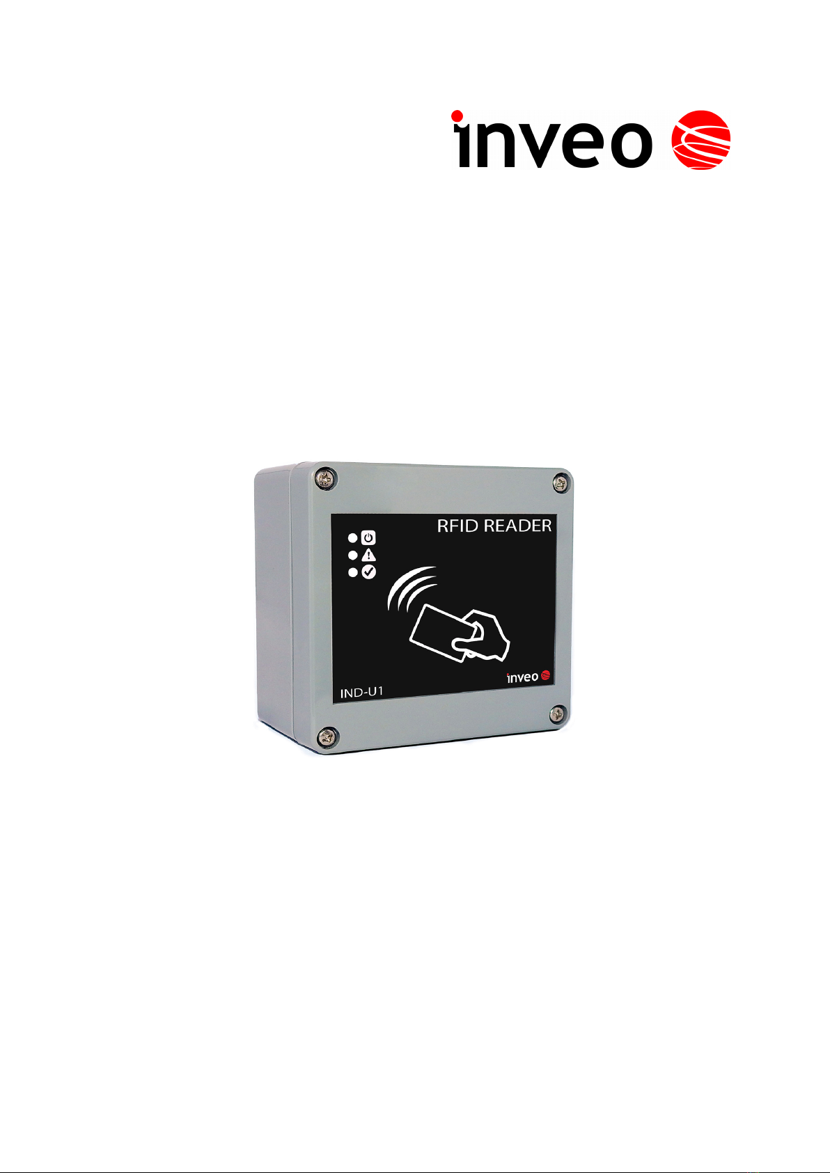
6.1 Outputs
The reader is has 2 relay outputs. Each output can be programmed separately. The fields
in the Outputs segment are used to configure the output settings.
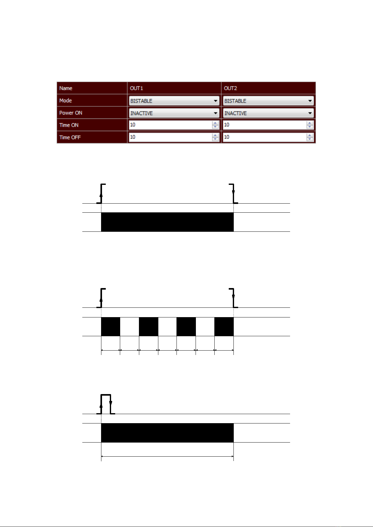
Mode – Sets the output mode. The output can work in the following modes:
•Disable – output is disabled,
•Bistable mode – a relay has one determined status (is engaged or disengaged).
•Astable mode – if the channel will be enabled, the relay is engage and disengage
cyclically. Time of engage and disengage relay:
- Time On – time when a relay is engaged,
- Time Off – time when a relay is disengaged.
•TIME – the output will enable for the Time ON and then the output will disable
(e.g. the control of the electromagnet).
User manual RFID IND Modbus-Uni Page 10 of 15
B03]
t
on
t
off
t
on
t
off
t
on
t
off
t
on
t
on
t
on
t
off
t
on
t
off
t
on
t
off
t
on
t
on
t
on
t
off
t
on
t
off
t
on
t
off
t
on
t
on
Other manuals for IND-U1
1
Table of contents
Other inveo Card Reader manuals


Popular Card Reader manuals by other brands


ViziT
ViziT RD-4F operating instructions

Jinmuyu Electronics
Jinmuyu Electronics MR811 Series user manual

Conrad
Conrad PCMCIA operating instructions

Lindy
Lindy 51541 user manual

Diapro T?bbi Ürünler
Diapro T?bbi Ürünler Across System user manual

Johnson Controls
Johnson Controls Kantech tyco ioSmart installation guide


