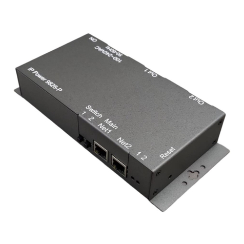
IP Power 9258 User manual

- 1 -
IP Power 9828
User Manual
Version: 1.00
Firmware Version: 1.09
Date Released: March . 2019

- 2 -
Warning: Any changes made to this equipment without permission may cause damages to the device!
IMPORTANT NOTICE
1. IP Power 9828 was designed for indoor use, we carry no responsibility for possible damages
caused by outdoor use, especially in the rain.
2. Please use the power adapter provided by the dealer, we carry no responsibility for the
possible damage from using power adapters not provided by us. .
4. Do not shake the IP Power 9828 in any fashion
5. Please contact the dealer If IP Power 9828 is not working properly.
Copyright © 2019 All rights reserved. No part of this publication may be reproduced, stored in a
retrieval system, or transmitted in any form or by any means, electronic, mechanical,
photocopying, recording or otherwise, without the prior written consent of us.
All trademarks and products mentioned in this document are the properties of us.

- 3 -
Table of Content
WELCOME...........................................................................................................5
Introduction .................................................................................................................................................. 5
Features :....................................................................................................................................................... 6
Specification.................................................................................................................................................. 6
Minimum System Requirements................................................................................................................. 7
Package Contents ......................................................................................................................................... 7
INTERFACE DESCRIPTION................................................................................8
Outlook.......................................................................................................................................................... 8
SETTING UP YOUR DEVICE...............................................................................8
Before Starting.............................................................................................................................................. 8
Hardware Connection.................................................................................................................................. 9
Software Installation...................................................................................................................................10
Network Connecting by LAN...................................................................................................................10
Internet Setup............................................................................................................................................12
Using IP Service .......................................................................................................................................13
WEB INTERFACE..............................................................................................14
Connect to your Device..............................................................................................................................14
Device name :...............................................................................................................................................16
Device Name & Display / Hide the left setting section : ..........................................................................16
Information :................................................................................................................................................17
Date and Time : .......................................................................................................................................17
Current Usage & Temperature :..............................................................................................................18
IO Control :..................................................................................................................................................18
Control......................................................................................................................................................19
Schedule....................................................................................................................................................24
Ping...........................................................................................................................................................27
Network :......................................................................................................................................................31
LAN Network Settings : ...........................................................................................................................31
Application Settings : ..................................................................................................................................34
Email.........................................................................................................................................................34
DDNS .......................................................................................................................................................39

- 4 -
Communication ........................................................................................................................................40
IP SERVICE.............................................................................................................................................43
System Setting : ...........................................................................................................................................45
Management .............................................................................................................................................45
System Information ..................................................................................................................................49
System Log...............................................................................................................................................49
Firmware...................................................................................................................................................50
CONTROLLING THE DEVICE...........................................................................51
CGI HTTP Commands.............................................................................................................................51
Telnet Control..............................................................................................................................................53
FAQ :..................................................................................................................54

- 5 -
Welcome
Introduction
IP Power 9828 is a new generation of the Power Distribution Unit (PDU) & Remote Power
Control (RPC) system.
With embedded web server and HTTPS protection , 9828 supports higher grade security as
working on Internet. User can control power easily and more safely through the web browser in
Windows , Android or iOS system , like Internet Explorer (IE) , Google Chrome , Safari web
browser or control through APP in Android or in iOS system .
With 2 buttons on device front , it allows user to direct control manually to each port ON/OFF with
fingertip without web browser / APP , also allows remote control power on/off up to 2 separate
devices via network .
As support SSL & SNMP, user can use public email like Gmail / Hotmail / Yahoo Mail to get the
email as the ON/OFF status changed . User can also control by e-mail without doing port
forwarding / port mapping and search the other IP Device in webpage directly and quick .
9828 supports Auto Ping , Time Scheduler which is more suitable for factory / commercial /
office / home automation . User can get the device status in LOG information or in remote IP
address which sent to get LOG message from 9828 ( SYSLOG ) . .
For system integrator, there are several popular developing tolls like HTTP/CGI command ,
Telnet , SNMP , Modbus TCP/IP & BACnet TCP/IP .
The various applications of the 9828 includes:
Power Management, Server Management, Internet Controllable Timer,
System Integration, Remote Power Control in Remote locations ………….. etc.
User Friendly . Convenience & Powerful ,

- 6 -
Product Overview
Features :
1. 2 ports Remote power controller for power On, Off and Reboot by the magnetic Latching
Relay ( See note )
2. 2 Buttons Control : Direct manual hardware control each outlet without working on Web
browser .
3. 2 Network ports ( RJ45) : one for Internet and another for HUB ( by pass)
4. Current meter for total Amp ( 2 ports total ) .
5. Web Server built-in design, directly control by web browser in Windows , Android or
iOS system like Internet Explore (IE) , Google Chrome and so on .
6. Support HTTPS , SSL , TCP/ IP , DHCP, DDNS , SMTP , Telnet , SNMP , Modbus/TCP
and BACnet/IP .
7. Power Surge protection & FUSE embedded in .
8. SYSLOG : Support Log function & send to assign IP address
9. Time Schedule - can pre-set a suitable time to turn power on / off automatically .
10. Auto Ping for network control & segment management automatically
11. High grade components for long stability and performance
12. Back Up for quick setup for multiple devices like Time Schedule, Network Setting.
13. Support public e-mail -- @gmail.com , @yahoo.com , @hotmail. com ..........etc.
E-mail Control & Advice :
- Receive e-mail with IPs device boot up.
- POP3 Control–Control each outlet ON/OFF via E-mail. No need to do Port Forwarding .
14. Specific software developed by Aviosys and provided free of charge :
- SDK Available : HTTP Command
- Windows software “ IP Power Center “ : Control Multiple Aviosys IP Power devices
in one software
- CNT software ( Cross Network Technology )- allows user eliminate set up work on
any Router without port forwarding , simply Plug & Play .
- Support MQTT protocol.
15. Support APP for Android or iOS system :
- Android APP -- name “IP Power “ free download in Google Play .
-iOS APP -- name “IPPOWER+ “ free download in Apple App Store
Specification

- 7 -
⚫Power input : 15A / 90-120VAC , 10A / 210-240VAC , 50-60Hz.
⚫Maximum loading of each output: 10Amp
⚫Maximum of Total loading : 10Amp
⚫Fuse protection : 10Amp
⚫Dimensions: 200 x 140 x 35 mm ( L x W x H )
⚫Weight: g
⚫Enclosure –Matel case in deep Gray color
⚫Operation Temperature : -10 ~ 60 ℃or 14 ~104(℉)
⚫Note : Use the magnetic “Latching Relay “(a KEEP relay ) , operation temperature
can go up to 85°C (185 °F) with MTBF 100K times , longer electrical life
expectancy . It keeps device operating temperature at low state and maintain there
without going higher even all 4 port at ON state simultaneously , plus lower power
consumption forenergy savings purpose. When power is turned OFF, all contacts
are available for other circuit functions and maintains its position, the circuit will be
in the same state when power is turned ON again.
Minimum System Requirements
⚫Network & Web Browser & Internet Connection
⚫Ethernet Cable & Power Cord
Package Contents
⚫9828 Unit
⚫Online CD note : www.aviosys.com/cd

- 8 -
Interface Description
Outlook
Front :
Switch 1& 2 for
Buttons Control outlets
The two buttons are for emergency safety switch
The default function is Toggle ( Switch ON / OFF ) .
But the buttons function can be setup as 6 modes :
OFF, ON, Shut down on Lan , Wake on Lan , Toggle or
None .
Disable , . Please go to webpage “I/O Control “→
“Control “→“Advanced ”→“Emergency safety switch
setting ”
Main Net 1
LAN 10/100 Mbps network for Internet
Net 2
HUB for bypass the signal of Net 1 ( LAN 10/100 Mbps network )
LED 1 & 2
Display the 2 outlets as ON or OFF
Back :
Outlet 1 & 2
IEC320 ,
Maximum Current : 10Amp ( for total two ports / single port )
Power input
15A / 90-120VAC , 10A / 210-240VAC , 50-60Hz.
Power Switch
Turn ON / OFF the power of 9828 devices.
Right Side :
Reset
Please keep pressing the button for 7 seconds and then
release .You will hear 3 short beep sound which show the reset
Successfully . After reset , all the settings , like IP, password and
so on , will be back to Default .
Setting up your device
Before Starting
*Before setting up the device make sure of the following:
1.) All the package contents are all included if anything is missing please contact the dealer
where the device was purchased from.
2.) Check the power input cable is working correctly.
3.) Check all cables to make sure there are no problems with it.

- 9 -
Hardware Connection
Before hardware connection, please make sure that there is no more than 2 net
work card ( include dynamic network card ) . If there are morn than two network
card in your PC. You may not get the IP address of 9828
The default setting of 9828 `s IP is by DHCP assigned by Router. The connection sequence is
different as connect to Router or connect to PC directly. Please refer following procedure :
A. 9828 ------- Router ------- PC ( with Web browser )
1.) Connect the Ethernet cable (RJ45) to the 9828 to your local area network.
2.) Then connect the power cable into the power input port of the 9828.
3.) Connect the device that you would like to control to the output plug on the top of the 9828.
4.) Switching the power source to ON status , this switch is located at the rear of 9828.
5.) After power on for around 45 seconds , there is a short beep sound for 9828 which means
the system reboot successfully
B. 9828 ------------- PC ( with Web browser )
If you select to connect to PC directly , please connect the RJ45 cable to 9828 after 1 minutes as
power on of the 9828 device . power hear the beep sound of 9828 DO NOT connect the RJ45 as
power ON
If you select to connect to you PC to 9828 directly :
1.) Connect the power cable to 9828 and press the power switch to ON
2.) After 9828 power on for around 45 seconds , there is a short beep sound for 9828 which
means the system reboot successfully
3.) Then Connect the Ethernet cable (RJ45) to the 9828 to your PC.
6.) Execute the software IPEDIT.exe to get the IP as 192.168.1.169
7.) Please make sure the IP address of you PC is also 192.168.1.X / XX/XXX or you may not
log in the 9828 webage in 192.168.1.169

- 10 -
Software Installation
Please go to our webpage www.aviosys.com/cd to get the software and manual of your product.
Under windows system, we offer two software :
1. IP Edit ( Required to search IP address )
2. IP Power Center ( For multiple IP Power devices control purpose )
Download the required software –IPEdit.exe - by clicking on the download button.
Network Connecting by LAN
LAN connect by IP search software “ IPEDIT “
IP Edit is a search tool designed to search, configure, or access the IP Power 9828 from a local
network computer.
IP Power 9828 Default Login / Password
Please use our IP Search tool “IPEDIT.exe “ to get the IP address of 9828 .
1.) In the local devices section user will see user device shows up if connection is correct.

- 11 -
Default as DHCP status , 9828 will auto get the IP address from user`s router by the suggest
hardware connection as following :
9828 ------- Router ------- PC ( with Web browser )
If there is no assigned IP to 9828 by the connection , the 9828 will change to FIX IP address :
⚫Default IP: 192.168.1.169 (While this is no DHCP apparently)
If can’t see the IP in the area of Local Devices of IPEDIT.exe. Please check if use more
than one network card ( include dynamic network card ) , disable the Firewall and Anti
Virus software temporally and try again.
2.) Select the 9828 device and the device information will pop up on the right.
3.) Check to see that the gateway IP and the IP Address (9828) match user current network.
If not, type in the correct information, then hit the “ Submit “ button to save changes.
For example:
If user has the following information regarding the 9828 and user network
User PC Network :
Computer IP Address: 192.168.1.122 , Gateway: 192.168.1.1
Sub Net mask: 255.255.255.0 , Port: 80
User 9828 in IPEDIT :
9828 IP Address: 192.168.100.34 , Gateway: 192.168.100.1
Sub Net mask: 255.255.0.0 , Port: 80
Since the IP Address of the 9828 is : 192.168.100.34
User will need to make sure that the first 3 segments of user 9828 IP Address
must match the first 3 segments of user gateway IP.
First 3 Segment of Gateway Address: 192.168.1.X
So user new IP Address for the 9828 should be: 192.168.1.XXX
New Network Information
9828 IP Address: 192.168.1.26
Gateway Address: 192.168.1.1 , Local Computer IP Address: 192.168.1.122
Sub Net mask: 255.255.255.0 , Port: 80
4.) Press the “ Rescan “ button to see if changes have been made.
5.) Double click on the device in the local device section and an IE web browser
with the device login will pop up.
6.) Type in the default Login and IP Address to enter the device.
Default Login : admin , Default : 12345678

- 12 -
Notice :
* User can click " REF " in IEPDIT to auto search proper IP setting for 9828.
It will take few minutes to show the suggest wizard.
Please click “ APPLY “as seeing the suggest wizard , click " yes " to ignore the remind message
of IP being used and then type the Username and Password to change the IP setting.
Username : admin Password : 12345678
Notice :
# Segment : The first 9 digits of the IP Address .
EX: The IP of user PC is 192.168.100.122. If the “ Local IP Address “ at WiFi Info is 192.168.100.
x ( X can the value of 1~252 ) , user PC can get into the webpage of 9828 .
# Please press “Rescan “ to search the router nearby again if can not see user router in the list.
Internet Setup
To connect the IP Power 9828 on Internet, there are two ways
⚫Setup Port Mapping / Port Forwarding in your router. Please check your Router owner’s
manual .
⚫Use our own software “ IP Power Center “ : Please refer to the “IP Power Center “ manual
in the online CD website .

- 13 -
Using IP Service
IP Service is a function which allows user to search for the device easily without having to
remember long complicated IP address. Instead, if user know the device’s name of user’s IP
Power device and user can easily find IP Address with IP Service. To log in the webpage of
9828 on Internet , user still need to do the “Port Forwarding “ in own router.
Before using “IP Service “ , please change the device name of user 9828 to avoid similar
name in Host Server.
1.) Open IP Edit and select the server that user’s 9828 is designated to.
Hit the “ Round Green color Connect button “ on the top of IP Edit screen shot below.
2.) Then type in the 9828 Name that user have selected for the device and press the Search
button.
3.) Find user device and double click on the screen and a IE window will pop up connecting to
user device. *User device must be Port Forwarded for the login screen to appear.
EX: The 9828 device name as IP_POWER , and user can search the device easily :
4.) After user has connected to user device, type in the Login and Password for user device

- 14 -
Web Interface
Connect to your Device
Once the 9828 has been setup correctly, log into the device.
First Option
1.) Go to IP Edit to find the device that is being used
2.) Double click on the device linked and an IE window will appear with the loading screen
Second Option
1.) Open Internet Explorer type in the IP Address of the device followed by the : sign.
For example: http:192.168.122.188:9258
192.168.122.188 –IP Address
2.) Once you have typed in the IP address of the 9828 and it is ready to be worked.
The default Username and Password for the 9828
Username : admin
Password: 12345678
The Control Console
The Right side Menu of the Web Interface for controlling the functionality and setup of the IP
Power 9828.

- 15 -
The IP Power 9828 Console consists of six main sections which will be explained in details below.
⚫Device name : Hide or Display the left setting column ( for smart phone control )
⚫Information : Date , Current Amp Usage &
⚫IO Control : Control , Schedule & Ping.
⚫Network : Setting
⚫Application : Email , DDNS, Communication & IP Service
⚫System : Management, Information, SysLog & Firmware
⚫Logout

- 16 -
Device name :
This section show the device name
You can change the device name here : Application →IP Server →Device name
Please change the name in English only and do not use symbol like !@#$%^&*()_+
Device Name & Display / Hide the left setting section :
For Smartphone user to control 9828 easily , user can select to show or to hide the left control
section by pressing the blue area near device name for Smartphone control :
- With left control section :
-
Without left control section :

- 17 -
Information :
Date and Time :
In this section, it shows Time at Year –Month –Date , Hours : Minutes : Seconds .
To setup the Time , Please go to “ System →Management →NTP Settings “ , please press
“Apply” to save the new setting .

- 18 -
Current Usage & Temperature :
⚫Current : It show the toal current usage of outlet 1 & 2. The maximum current is at 10A .
⚫Temperature: It show the temperature of the 9828 box inside -10 ~ 60 ℃or
14 ~104(℉)20190227 Tim will ask Andy on 0304
⚫. If the temperature show over (
IO Control :
The IO Control Section allows you to directly / automatically control the outlets of the 9828 as well
as schedule Daily, Weekly, and Monthly power cycles.
There are five sections : Control , Schedule , Ping , Timeline and History.

- 19 -
Control
There are 2 setting pages in this Section. One is “ Power Control “ and another one is “Advance
Setup “
A. Power Control :
User can do the following 3 basic operation in this page :
1. Manual control each port ON or OFF directly by pressing the power sign.
2 Power Cycle control : Manually Control the relay delay to turn ON / OFF . The relay cycle
time can be set from 1 to 9999 seconds
User can set up the time and the final status in power cycle as ON / OFF
For example : ( sec = seconds )
-Original Outlet as “ OFF “ , select final status as “ ON “ & fill 15sec :
After press power cycle button, the outlet will turn OFF for 15 seconds and then turn ON .
OFF ( 15 sec ) →ON
-Original Outlet as “ ON “ , select final status as “ ON “ & fill 10sec :
After press power cycle button, the outlet will turn OFF for 10 seconds and
then turn ON .
ON -- > OFF ( 10 sec ) →ON
-Original Outlet as “ OFF “ , select final status as “ OFF “ & fill 8 sec :
After press power cycle button, the outlet will turn ON for 8 seconds and
then turn OFF .

- 20 -
OFF →ON ( 8 sec ) →OFF
-Original Outlet as “ ON “ , select final status as “ OFF “ & fill 5 sec :
After press power cycle button, the outlet will be ON for 5 seconds and
then turn OFF .
ON ( 5 sec ) →OFF
Notice :
As use Latching Relay in IP 9825 , there is no difference of Normal Closed Relay (NC) or Normal
Open Relay (NO) . As there is no power for 9825 device , the relay status will keep as it is at ON
or at OFF .
3 Group Setting : User can control more than one outlet by press the right side “Apply
“ button . For safety concern , each port of 9828will turn ON or OFF one after one .
For example : The below picture means that Power #1 is ON , Power #2 is OFF
The following 3 pictures shows that after press the power cycle with 5 seconds setting , the
outlet “ Power1 “ will turn off for 5 seconds , then turn ON later . The power cycle action will
execute after press the “ Power Cycle “ button .
Other manuals for 9258
2
Table of contents
Other IP Power Switch manuals
Popular Switch manuals by other brands

Avocent
Avocent AMX5100 brochure

KHE AUDIO ELECTRONICS
KHE AUDIO ELECTRONICS AFX 8 Setup instructions

Cisco
Cisco Nexus 93108TC-FX3P Hardware installation guide

Aube Technologies
Aube Technologies TI034-3W Installation and user guide

Hama
Hama Quad Switch LNB operating instructions

HP
HP Procurve Series 4100GL Installation and getting started guide

Opencockpits
Opencockpits A320 Sidestick PRO Installation & user manual

Cisco
Cisco 3020 - Cisco Catalyst Blade Switch release note

Club 3D
Club 3D CSV-7300 Quick installation guide

APT
APT LW39-16A Series instructions

Gigabyte
Gigabyte GN-GSV2401M user guide

ZyXEL Communications
ZyXEL Communications ES-2024A release note